2008 INFINITI FX35 roof rack
[x] Cancel search: roof rackPage 592 of 3924

AUDIOAV-45
< SERVICE INFORMATION >
C
DE
F
G H
I
J
L
M A
B
AV
N
O P
3. Remove nuts (2) with power tool, and remove assist bracket.
4. Remove nuts (4) with power tool, and remove bracket.
INSTALLATION
Installation is the reverse order of removal.
Removal and Installation of Satellite Radio TunerINFOID:0000000001328700
REMOVAL
1. Remove luggage side box assembly. Refer to EI-45, "Component Parts Location".
2. Remove nuts (A) and remove satellite radio tuner (1) from lug- gage room floor.
INSTALLATION
Installation is the reverse order of removal.
Removal and Installation of Satellite Radio AntennaINFOID:0000000001328701
: Vehicle front
REMOVAL
1. Remove luggage floor trim. Refer to EI-45, "Component Parts Location".
2. Remove assist grip (rear). Refer to EI-43
.
3. Pull down headlining and obtain space for work between vehicle and headlining.
4. Remove nut (A), and then disconnect connector (1).
5. Remove satellite radio antenna.
INSTALLATION
Installation is the reverse order of removal.
SKIA5809E
SKIB8650E
SKIB8668E
Roof antenna mounting nut : 4.5 N·m (0.46 kg-m, 40 in-lb)
3AA93ABC3ACD3AC03ACA3AC03AC63AC53A913A773A893A873A873A8E3A773A983AC73AC93AC03AC3
3A893A873A873A8F3A773A9D3AAF3A8A3A8C3A863A9D3AAF3A8B3A8C
Page 720 of 3924

TELEPHONEAV-173
< SERVICE INFORMATION >
C
DE
F
G H
I
J
L
M A
B
AV
N
O P
2. Remove screws (A) and remove TEL antenna (1) from bracket.
INSTALLATION
Installation is the reverse order of removal.
Removal and Installation of MicrophoneINFOID:0000000001328800
REMOVAL
1. Remove roof console. Refer to EI-43.
2. Remove screws (A) and remove microphone (1) from roof con- sole.
INSTALLATION
Installation is the reverse order of removal.
SKIB8669E
SKIB8670E
3AA93ABC3ACD3AC03ACA3AC03AC63AC53A913A773A893A873A873A8E3A773A983AC73AC93AC03AC3
3A893A873A873A8F3A773A9D3AAF3A8A3A8C3A863A9D3AAF3A8B3A8C
Page 744 of 3924

BL-10
< SERVICE INFORMATION >
SQUEAK AND RATTLE TROUBLE DIAGNOSIS
Most of these incidents can be repaired by adjusting, securing or insulating the item(s) or component(s) caus-
ing the noise.
SUNROOF/HEADLINING
Noises in the sunroof/headlining area c an often be traced to one of the following:
1. Sunroof lid, rail, linkage or seals making a rattle or light knocking noise
2. Sunvisor shaft shaking in the holder
3. Front or rear windshield touching headlining and squeaking
Again, pressing on the components to stop the noise while duplicating the conditions can isolate most of these
incidents. Repairs usually consist of insulating with felt cloth tape.
SEATS
When isolating seat noise it's important to note the pos ition the seat is in and the load placed on the seat when
the noise is present. These conditions should be dupl icated when verifying and isolating the cause of the
noise.
Cause of seat noise include:
1. Headrest rods and holder
2. A squeak between the seat pad cushion and frame
3. The rear seatback lock and bracket
These noises can be isolated by moving or pressing on the suspected components while duplicating the con-
ditions under which the noise occurs. Most of thes e incidents can be repaired by repositioning the component
or applying urethane tape to the contact area.
UNDERHOOD
Some interior noise may be caused by components under the hood or on the engine wall. The noise is then
transmitted into the passenger room.
Causes of transmitted underhood noise include:
1. Any component mounted to the engine wall
2. Components that pass through the engine wall
3. Engine wall mounts and connectors
4. Loose radiator mounting pins
5. Hood bumpers out of adjustment
6. Hood striker out of adjustment
These noises can be difficult to isolate since they cannot be reached from the interior of the vehicle. The best
method is to secure, move or insulate one component at a time and test drive the \
vehicle. Also, engine RPM
or load can be changed to isolate the noise. Repairs can usually be made by moving, adjusting, securing, or
insulating the component causing the noise.
3AA93ABC3ACD3AC03ACA3AC03AC63AC53A913A773A893A873A873A8E3A773A983AC73AC93AC03AC3
3A893A873A873A8F3A773A9D3AAF3A8A3A8C3A863A9D3AAF3A8B3A8C
Page 2445 of 3924

EI-8
< SERVICE INFORMATION >
SQUEAK AND RATTLE TROUBLE DIAGNOSES
Most of these incidents can be repaired by adjusting, securing or insulating the item(s) or component(s) caus-
ing the noise.
SUNROOF/HEADLINING
Noises in the sunroof/headlining area c an often be traced to one of the following:
1. Sunroof lid, rail, linkage or seals making a rattle or light knocking noise
2. Sun-visor shaft shaking in the holder
3. Front or rear windshield touching headlining and squeaking
Again, pressing on the components to stop the noise while duplicating the conditions can isolate most of these
incidents. Repairs usually consist of insulating with felt cloth tape.
SEATS
When isolating seat noise it's important to note the pos ition the seat is in and the load placed on the seat when
the noise is present. These conditions should be dupl icated when verifying and isolating the cause of the
noise.
Cause of seat noise include:
1. Headrest rods and holder
2. A squeak between the seat pad cushion and frame
3. The rear seatback lock and bracket
These noises can be isolated by moving or pressing on the suspected components while duplicating the con-
ditions under which the noise occurs. Most of thes e incidents can be repaired by repositioning the component
or applying urethane tape to the contact area.
UNDERHOOD
Some interior noise may be caused by components under the hood or on the engine wall. The noise is then
transmitted into the passenger compartment.
Causes of transmitted under-hood noise include:
1. Any component mounted to the engine wall
2. Components that pass through the engine wall
3. Engine wall mounts and connectors
4. Loose radiator mounting pins
5. Hood bumpers out of adjustment
6. Hood striker out of adjustment
These noises can be difficult to isolate since they cannot be reached from the interior of the vehicle. The best
method is to secure, move or insulate one component at a time and test drive the \
vehicle. Also, engine RPM
or load can be changed to isolate the noise. Repairs can usually be made by moving, adjusting, securing, or
insulating the component causing the noise.
3AA93ABC3ACD3AC03ACA3AC03AC63AC53A913A773A893A873A873A8E3A773A983AC73AC93AC03AC3
3A893A873A873A8F3A773A9D3AAF3A8A3A8C3A863A9D3AAF3A8B3A8C
Page 2470 of 3924

ROOF RAILEI-33
< SERVICE INFORMATION >
C
DE
F
G H
J
K L
M A
B
EI
N
O P
ROOF RAIL
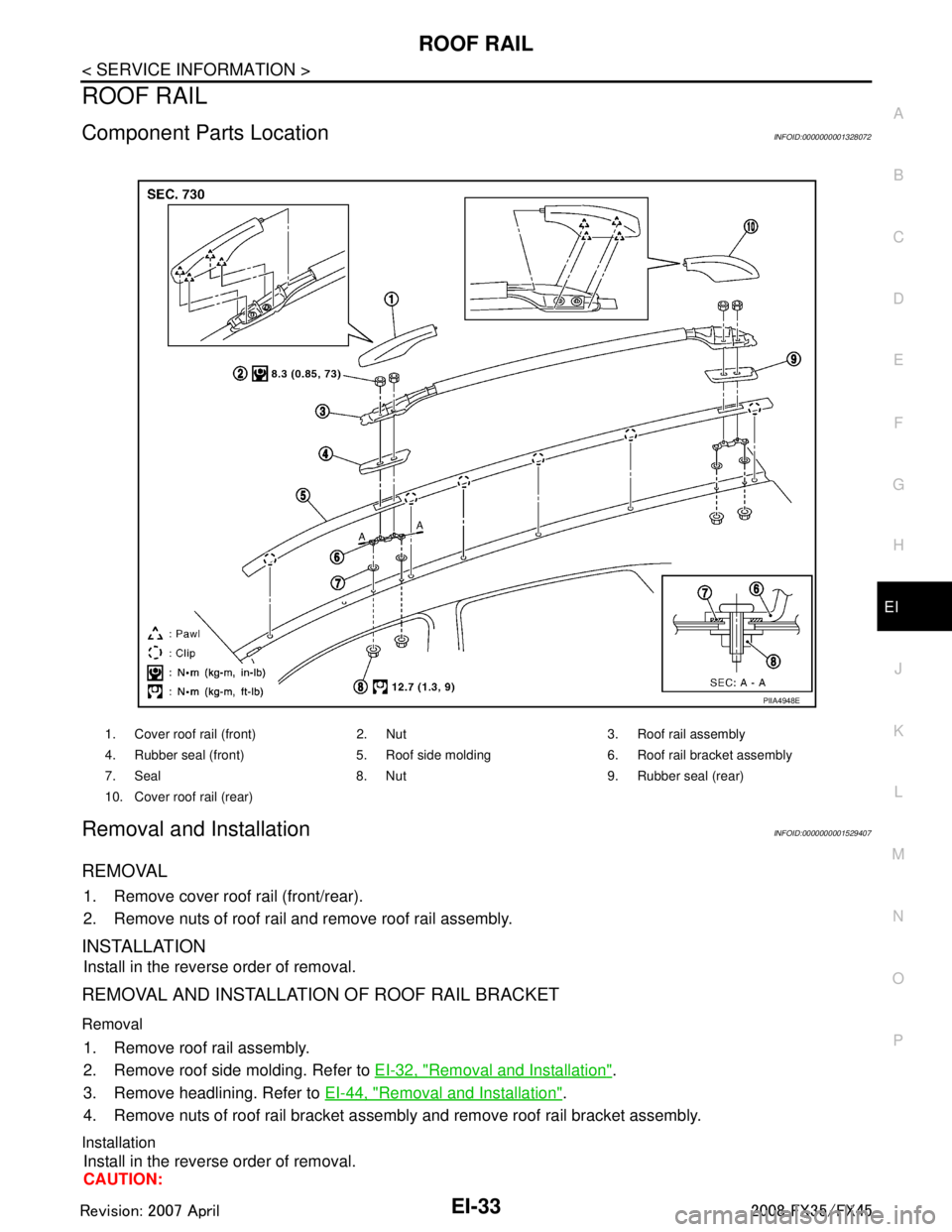
Component Parts LocationINFOID:0000000001328072
Removal and InstallationINFOID:0000000001529407
REMOVAL
1. Remove cover roof rail (front/rear).
2. Remove nuts of roof rail and remove roof rail assembly.
INSTALLATION
Install in the reverse order of removal.
REMOVAL AND INSTALLATION OF ROOF RAIL BRACKET
Removal
1. Remove roof rail assembly.
2. Remove roof side molding. Refer to EI-32, "
Removal and Installation".
3. Remove headlining. Refer to EI-44, "
Removal and Installation".
4. Remove nuts of roof rail bracket assembly and remove roof rail bracket assembly.
Installation
Install in the reverse order of removal.
CAUTION:
1. Cover roof rail (front) 2. Nut 3. Roof rail assembly
4. Rubber seal (front) 5. Roof side molding 6. Roof rail bracket assembly
7. Seal 8. Nut 9. Rubber seal (rear)
10. Cover roof rail (rear)
PIIA4948E
3AA93ABC3ACD3AC03ACA3AC03AC63AC53A913A773A893A873A873A8E3A773A983AC73AC93AC03AC3
3A893A873A873A8F3A773A9D3AAF3A8A3A8C3A863A9D3AAF3A8B3A8C
Page 2835 of 3924

FUEL SYSTEMFL-3
< SERVICE INFORMATION >
C
DE
F
G H
I
J
K L
M A
FL
NP
O
FUEL SYSTEM
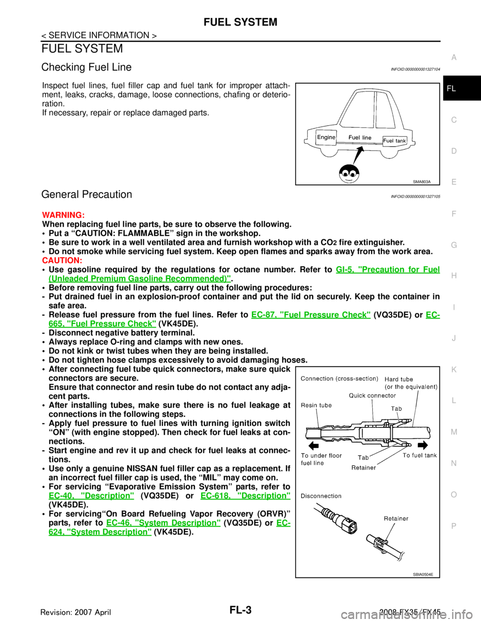
Checking Fuel LineINFOID:0000000001327104
Inspect fuel lines, fuel filler cap and fuel tank for improper attach-
ment, leaks, cracks, damage, loos
e connections, chafing or deterio-
ration.
If necessary, repair or replace damaged parts.
General PrecautionINFOID:0000000001327105
WARNING:
When replacing fuel line parts, be sure to observe the following.
• Put a “CAUTION: FLAMMABLE” sign in the workshop.
Be sure to work in a well ventila ted area and furnish workshop with a CO
2 fire extinguisher.
Do not smoke while servicing fuel system. Keep open flames and sparks away from the work area.
CAUTION:
Use gasoline required by the regulations for octane number. Refer to GI-5, "
Precaution for Fuel
(Unleaded Premium Gasoline Recommended)".
Before removing fuel line parts, carry out the following procedures:
- Put drained fuel in an explosion-proof containe r and put the lid on securely. Keep the container in
safe area.
- Release fuel pressure from th e fuel lines. Refer to EC-87, "
Fuel Pressure Check" (VQ35DE) or EC-
665, "Fuel Pressure Check" (VK45DE).
- Disconnect negative battery terminal.
Always replace O-ring and clamps with new ones.
Do not kink or twist tubes when they are being installed.
Do not tighten hose clamps excessi vely to avoid damaging hoses.
After connecting fuel tube qu ick connectors, make sure quick
connectors are secure.
Ensure that connector and resin tube do not contact any adja-
cent parts.
After installing tubes, make su re there is no fuel leakage at
connections in the following steps.
- Apply fuel pressure to fuel li nes with turning ignition switch
“ON” (with engine stopped). Th en check for fuel leaks at con-
nections.
- Start engine and rev it up and check for fuel leaks at connec- tions.
Use only a genuine NISSAN fuel filler cap as a replacement. If
an incorrect fuel filler cap is used, the “MIL” may come on.
For servicing “Evaporative Emi ssion System” parts, refer to
EC-40, "
Description" (VQ35DE) or EC-618, "Description"
(VK45DE).
For servicing“On Board Refueling Vapor Recovery (ORVR)”
parts, refer to EC-46, "
System Description" (VQ35DE) or EC-
624, "System Description" (VK45DE).
SMA803A
SBIA0504E
3AA93ABC3ACD3AC03ACA3AC03AC63AC53A913A773A893A873A873A8E3A773A983AC73AC93AC03AC3
3A893A873A873A8F3A773A9D3AAF3A8A3A8C3A863A9D3AAF3A8B3A8C
Page 2921 of 3924

GW-8
< SERVICE INFORMATION >
SQUEAK AND RATTLE TROUBLE DIAGNOSES
Most of these incidents can be repaired by adjusting, securing or insulatingthe item(s) or component(s) caus-
ing the noise.
SUNROOF/HEADLINING
Noises in the sunroof/headlining area c an often be traced to one of the following:
1. Sunroof lid, rail, linkage or seals making a rattle or light knockingnoise
2. Sunvisor shaft shaking in the holder
3. Front or rear windshield touching headlining and squeaking
Again, pressing on the components to stop the noise while duplicatingthe conditions can isolate most of these
incidents. Repairs usually consistof insulating with felt cloth tape.
SEATS
When isolating seat noise it's important to note the pos ition the seatis in and the load placed on the seat when
the noise is present. These conditionsshould be duplic ated when verifying and isolating the cause of the
noise.
Cause of seat noise include:
1. Headrest rods and holder
2. A squeak between the seat pad cushion and frame
3. The rear seatback lock and bracket
These noises can be isolated by moving or pressing on the suspectedcomponents while duplicating the condi-
tions under which the noise occurs.Most of these incidents can be repaired by repositioning the component
orapplying urethane tape to the contact area.
UNDERHOOD
Some interior noise may be caused by components under the hood or onthe engine wall. The noise is then
transmitted into the passenger compartment.
Causes of transmitted underhood noise include:
1. Any component mounted to the engine wall
2. Components that pass through the engine wall
3. Engine wall mounts and connectors
4. Loose radiator mounting pins
5. Hood bumpers out of adjustment
6. Hood striker out of adjustment
These noises can be difficult to isolate since they cannot be reached from the interior of the vehicle. The best
method is to secure, move or insulate one component at a time and test drive the \
vehicle. Also, engine RPM
or load can be changed to isolate the noise. Repairs can usually be made by moving, adjusting, securing, or
insulating the component causing the noise.
3AA93ABC3ACD3AC03ACA3AC03AC63AC53A913A773A893A873A873A8E3A773A983AC73AC93AC03AC3
3A893A873A873A8F3A773A9D3AAF3A8A3A8C3A863A9D3AAF3A8B3A8C
Page 2961 of 3924

GW-48
< SERVICE INFORMATION >
SIDE WINDOW GLASS
SIDE WINDOW GLASS
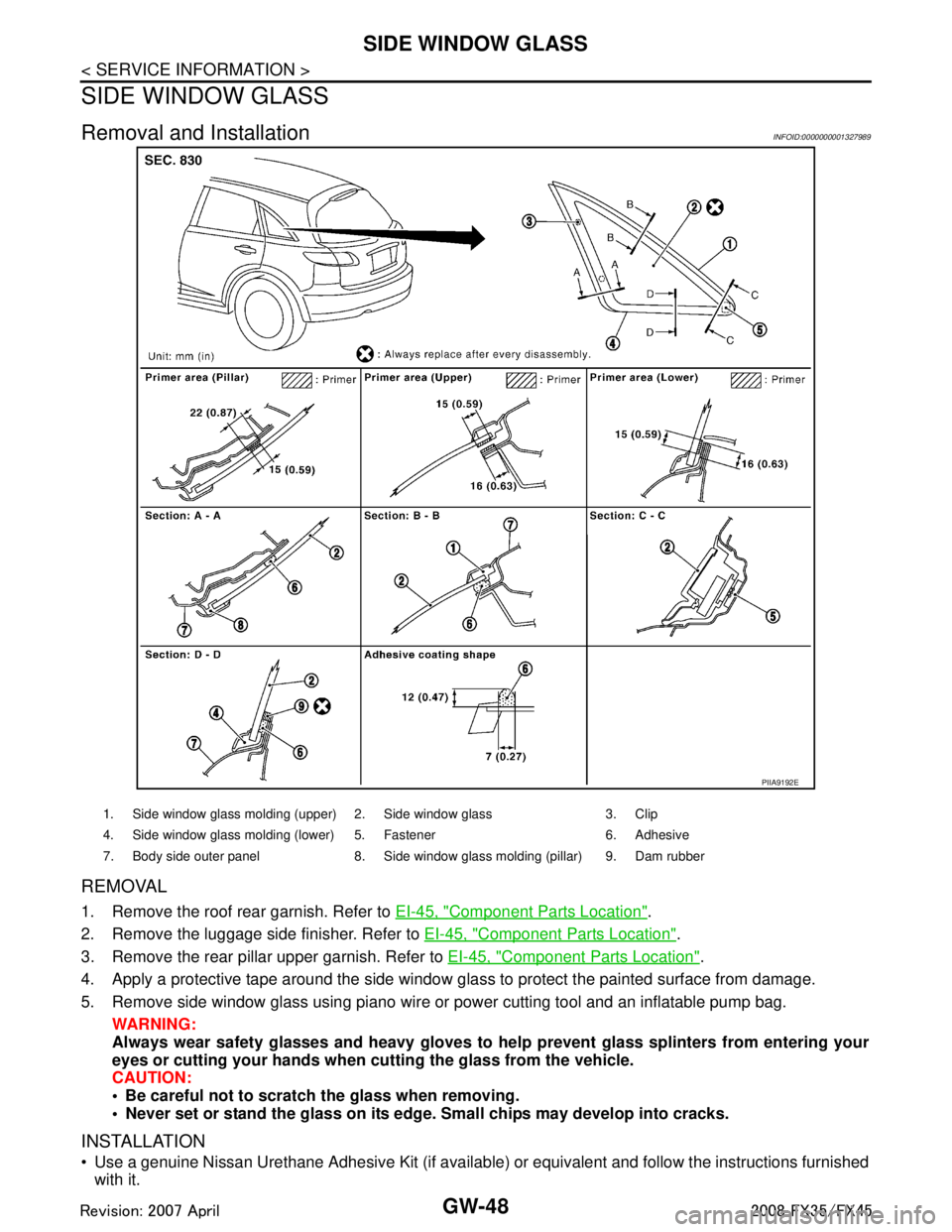
Removal and InstallationINFOID:0000000001327989
REMOVAL
1. Remove the roof rear garnish. Refer to EI-45, "Component Parts Location".
2. Remove the luggage side finisher. Refer to EI-45, "
Component Parts Location".
3. Remove the rear pillar upper garnish. Refer to EI-45, "
Component Parts Location".
4. Apply a protective tape around the side window gl ass to protect the painted surface from damage.
5. Remove side window glass using piano wire or power cutting tool and an inflatable pump bag. WARNING:
Always wear safety glasses and heavy gloves to help prevent glass splinters from entering your
eyes or cutting your hands when cu tting the glass from the vehicle.
CAUTION:
Be careful not to scratch the glass when removing.
Never set or stand the glass on its edge. Small chips may develop into cracks.
INSTALLATION
Use a genuine Nissan Urethane Adhesive Kit (if available) or equivalent and follow the instructions furnished
with it.
PIIA9192E
1. Side window glass molding (upper) 2. Side window glass 3. Clip
4. Side window glass molding (lower) 5. Fastener 6. Adhesive
7. Body side outer panel 8. Side window glass molding (pillar) 9. Dam rubber
3AA93ABC3ACD3AC03ACA3AC03AC63AC53A913A773A893A873A873A8E3A773A983AC73AC93AC03AC3
3A893A873A873A8F3A773A9D3AAF3A8A3A8C3A863A9D3AAF3A8B3A8C