2008 INFINITI FX35 wheel torque
[x] Cancel search: wheel torquePage 108 of 3924
A/T CONTROL SYSTEMAT-35
< SERVICE INFORMATION >
DE
F
G H
I
J
K L
M A
B
AT
N
O P
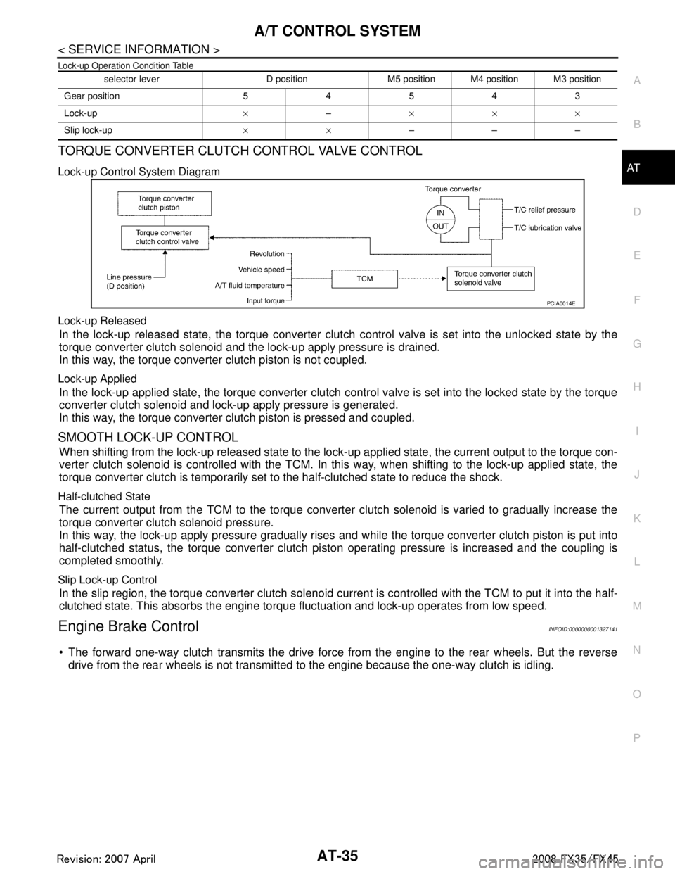
Lock-up Operation Condition Table
TORQUE CONVERTER CLUTCH CONTROL VALVE CONTROL
Lock-up Control System Diagram
Lock-up Released
In the lock-up released state, the torque converter clutch control valve is set into the unlocked state by the
torque converter clutch solenoid and the lock-up apply pressure is drained.
In this way, the torque converter clutch piston is not coupled.
Lock-up Applied
In the lock-up applied state, the torque converter clutch control valve is set into the locked state by the torque
converter clutch solenoid and lock-up apply pressure is generated.
In this way, the torque converter clutch piston is pressed and coupled.
SMOOTH LOCK-UP CONTROL
When shifting from the lock-up released state to the lock- up applied state, the current output to the torque con-
verter clutch solenoid is controlled with the TCM. In this way, when shifting to the lock-up applied state, the
torque converter clutch is temporarily set to the half-clutched state to reduce the shock.
Half-clutched State
The current output from the TCM to the torque converte r clutch solenoid is varied to gradually increase the
torque converter clutch solenoid pressure.
In this way, the lock-up apply pressure gradually rises and while the torque converter clutch piston is put into
half-clutched status, the torque converter clutch pi ston operating pressure is increased and the coupling is
completed smoothly.
Slip Lock-up Control
In the slip region, the torque converter clutch solenoid cu rrent is controlled with the TCM to put it into the half-
clutched state. This absorbs the engine torque fluctuation and lock-up operates from low speed.
Engine Brake ControlINFOID:0000000001327141
The forward one-way clutch transmits the drive force from the engine to the rear wheels. But the reverse
drive from the rear wheels is not transmitted to the engine because the one-way clutch is idling.
selector lever D position M5 position M4 position M3 position
Gear position 54543
Lock-up ×– ×××
Slip lock-up ××–––
PCIA0014E
3AA93ABC3ACD3AC03ACA3AC03AC63AC53A913A773A893A873A873A8E3A773A983AC73AC93AC03AC3
3A893A873A873A8F3A773A9D3AAF3A8A3A8C3A863A9D3AAF3A8B3A8C
Page 986 of 3924

BR-2
< SERVICE INFORMATION >
PRECAUTIONS
SERVICE INFORMATION
PRECAUTIONS
Precaution for Supplemental Restraint System (SRS) "AIR BAG" and "SEAT BELT
PRE-TENSIONER"
INFOID:0000000001612918
The Supplemental Restraint System such as “A IR BAG” and “SEAT BELT PRE-TENSIONER”, used along
with a front seat belt, helps to reduce the risk or severi ty of injury to the driver and front passenger for certain
types of collision. This system includes seat belt switch inputs and dual stage front air bag modules. The SRS
system uses the seat belt switches to determine the front air bag deployment, and may only deploy one front
air bag, depending on the severity of a collision and w hether the front occupants are belted or unbelted.
Information necessary to service the system safely is included in the “SUPPLEMENTAL RESTRAINT SYS-
TEM” and “SEAT BELTS” of this Service Manual.
WARNING:
• To avoid rendering the SRS inopera tive, which could increase the risk of personal injury or death in
the event of a collision which would result in air bag inflation, all maintenance must be performed by
an authorized NISS AN/INFINITI dealer.
Improper maintenance, including in correct removal and installation of the SRS, can lead to personal
injury caused by unintent ional activation of the system. For re moval of Spiral Cable and Air Bag
Module, see the “SUPPLEMEN TAL RESTRAINT SYSTEM”.
Do not use electrical test equipmen t on any circuit related to the SRS unless instructed to in this
Service Manual. SRS wiring harnesses can be identi fied by yellow and/or orange harnesses or har-
ness connectors.
Precaution for Procedure without Cowl Top CoverINFOID:0000000001612920
When performing the procedure after removing cowl top cover, cover
the lower end of windshield with urethane, etc.
Precaution for Brake SystemINFOID:0000000001327604
Clean dust on front brake and rear brake with a vacuum dust collector. Do not blow with compressed air.
Recommended fluid is brake fluid “DOT 3”. MA-9, "
Fluids and Lubricants".
Do not reuse drained brake fluid.
Be careful not to splash brake fluid on painted areas.
To clean or wash all parts of master cylinder, disc brake caliper and wheel cylinder, use new brake fluid.
Do not use mineral oils such as gasoline or kerosene. They will ruin rubber parts of the hydraulic system.
Use a flare nut crowfoot and torque wrench when installing brake
tube.
When installing brake piping, be sure to check torque.
Before working, turn ignition switch OFF and disconnect connec- tors for ABS actuator and electric unit (control unit) or battery neg-
ative terminal.
Burnish the brake contact surfaces after refinishing or replacing drums or rotors, after replacing pads or linings, or if a soft pedal
occurs at very low mileage.
Refer to BR-23, "
Brake Burnishing Procedure" (Front disc brake),
BR-29, "
Brake Burnishing Procedure" (Rear disc brake).
WARNING:
Clean brake pads and shoes with a waste cl oth, then clean with a dust collector.
PIIB3706J
SBR686C
3AA93ABC3ACD3AC03ACA3AC03AC63AC53A913A773A893A873A873A8E3A773A983AC73AC93AC03AC3
3A893A873A873A8F3A773A9D3AAF3A8A3A8C3A863A9D3AAF3A8B3A8C
Page 1003 of 3924
FRONT DISC BRAKEBR-19
< SERVICE INFORMATION >
C
DE
G H
I
J
K L
M A
B
BR
N
O P
While removing cylinder body, never depr ess brake pedal because piston will pop out.
It is not necessary to remove bolts on torq ue member and brake hose except for disassembly or
replacement of caliper assembly. In this case, suspe nd cylinder body with wire so as not to stretch
brake hose.
Do not damage piston boot.
If any shim is subject to serious corrosion, replace it with a new one.
Always replace shims and shim covers as a set when replacing brake pads.
Keep rotor clean, from brake fluid.
Burnish brake contact surface after refinishing or replacing rotors, after replacing pads, or it a soft
pedal occurs at very low mileage. Refer to BR-23, "
Brake Burnishing Procedure".
Removal and Installation of Brake PadINFOID:0000000001327629
REMOVAL
1. Remove tires from vehicle with power tool.
2. Remove lower sliding pin bolt.
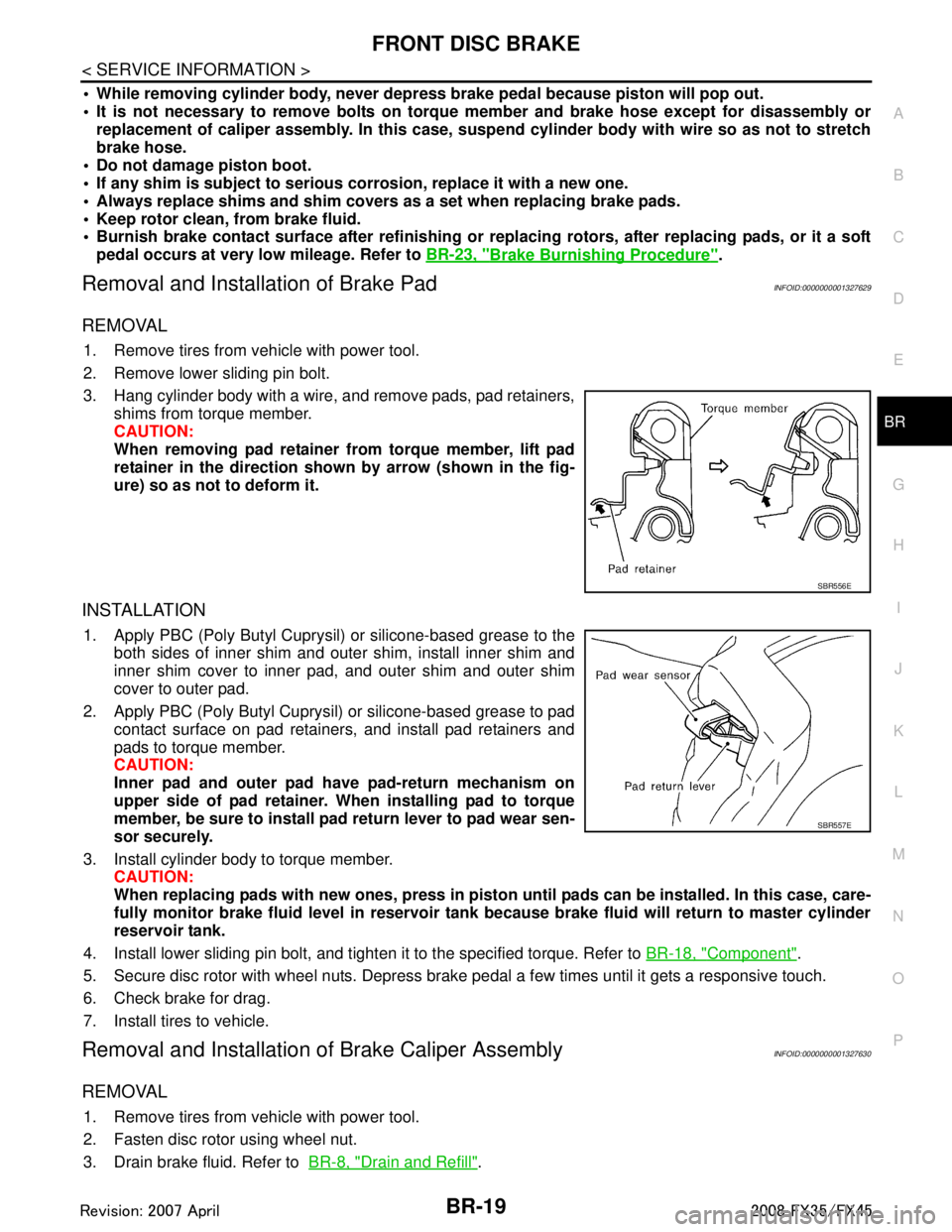
3. Hang cylinder body with a wire, and remove pads, pad retainers,
shims from torque member.
CAUTION:
When removing pad retainer from torque member, lift pad
retainer in the direction show n by arrow (shown in the fig-
ure) so as not to deform it.
INSTALLATION
1. Apply PBC (Poly Butyl Cuprysil) or silicone-based grease to the both sides of inner shim and outer shim, install inner shim and
inner shim cover to inner pad, and outer shim and outer shim
cover to outer pad.
2. Apply PBC (Poly Butyl Cuprysil) or silicone-based grease to pad contact surface on pad retainers, and install pad retainers and
pads to torque member.
CAUTION:
Inner pad and outer pad have pad-return mechanism on
upper side of pad retainer. When installing pad to torque
member, be sure to install pad return lever to pad wear sen-
sor securely.
3. Install cylinder body to torque member. CAUTION:
When replacing pads with new ones, press in piston until pads can be installed. In this case, care-
fully monitor brake fluid level in reservoir tank because brake fluid will return to master cylinder
reservoir tank.
4. Install lower sliding pin bolt, and tighten it to the specified torque. Refer to BR-18, "
Component".
5. Secure disc rotor with wheel nuts. Depress brake pedal a few times until it gets a responsive touch.
6. Check brake for drag.
7. Install tires to vehicle.
Removal and Installation of Brake Caliper AssemblyINFOID:0000000001327630
REMOVAL
1. Remove tires from vehicle with power tool.
2. Fasten disc rotor using wheel nut.
3. Drain brake fluid. Refer to BR-8, "
Drain and Refill".
SBR556E
SBR557E
3AA93ABC3ACD3AC03ACA3AC03AC63AC53A913A773A893A873A873A8E3A773A983AC73AC93AC03AC3
3A893A873A873A8F3A773A9D3AAF3A8A3A8C3A863A9D3AAF3A8B3A8C
Page 1004 of 3924
BR-20
< SERVICE INFORMATION >
FRONT DISC BRAKE
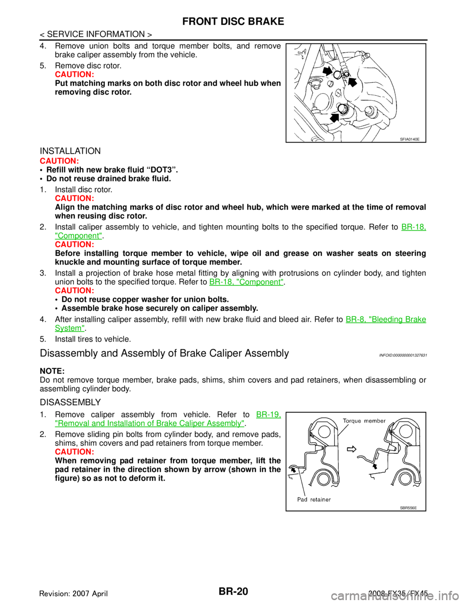
4. Remove union bolts and torque member bolts, and removebrake caliper assembly from the vehicle.
5. Remove disc rotor. CAUTION:
Put matching marks on both disc rotor and wheel hub when
removing disc rotor.
INSTALLATION
CAUTION:
Refill with new brake fluid “DOT3”.
Do not reuse drained brake fluid.
1. Install disc rotor.
CAUTION:
Align the matching marks of disc rotor and wheel hub, which were marked at the time of removal
when reusing disc rotor.
2. Install caliper assembly to vehicle, and tighten mounting bolts to the specified torque. Refer to BR-18,
"Component".
CAUTION:
Before installing torque member to vehicle, wipe oil and grease on washer seats on steering
knuckle and mounting surface of torque member.
3. Install a projection of brake hose metal fitting by aligning with protrusions on cylinder body, and tighten
union bolts to the specified torque. Refer to BR-18, "
Component".
CAUTION:
Do not reuse copper washer for union bolts.
Assemble brake hose securely on caliper assembly.
4. After installing caliper assembly, refill with new brake fluid and bleed air. Refer to BR-8, "
Bleeding Brake
System".
5. Install tires to vehicle.
Disassembly and Assembly of Brake Caliper AssemblyINFOID:0000000001327631
NOTE:
Do not remove torque member, brake pads, shims, shim covers and pad retainers, when disassembling or
assembling cylinder body.
DISASSEMBLY
1. Remove caliper assembly from vehicle. Refer to BR-19,
"Removal and Installation of Brake Caliper Assembly".
2. Remove sliding pin bolts from cylinder body, and remove pads, shims, shim covers and pad retainers from torque member.
CAUTION:
When removing pad retainer fr om torque member, lift the
pad retainer in the direction shown by arrow (shown in the
figure) so as not to deform it.
SFIA0140E
SBR556E
3AA93ABC3ACD3AC03ACA3AC03AC63AC53A913A773A893A873A873A8E3A773A983AC73AC93AC03AC3
3A893A873A873A8F3A773A9D3AAF3A8A3A8C3A863A9D3AAF3A8B3A8C
Page 1006 of 3924
BR-22
< SERVICE INFORMATION >
FRONT DISC BRAKE
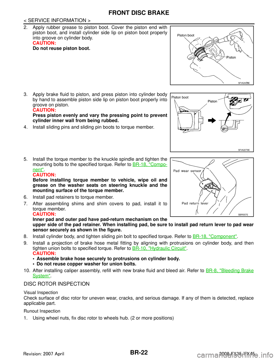
2. Apply rubber grease to piston boot. Cover the piston end withpiston boot, and install cylinder side lip on piston boot properly
into groove on cylinder body.
CAUTION:
Do not reuse piston boot.
3. Apply brake fluid to piston, and press piston into cylinder body by hand to assemble piston side lip on piston boot properly into
groove on piston.
CAUTION:
Press piston evenly and vary the pressing point to prevent
cylinder inner wall from being rubbed.
4. Install sliding pins and sliding pin boots to torque member.
5. Install the torque member to the knuckle spindle and tighten the mounting bolts to the specified torque. Refer to BR-18, "
Compo-
nent".
CAUTION:
Before installing torque member to vehicle, wipe oil and
grease on the washer seats on steering knuckle and the
mounting surface of the torque member.
6. Install pad retainers to torque member.
7. After assembling shims and shim covers to pad, install it to torque member.
CAUTION:
Inner pad and outer pad have pad-return mechanism on the
upper side of the pad retainer. When installing pad, be sure to install pad return lever to pad wear
sensor securely as shown in the figure.
8. Install cylinder body, and tighten sliding pin bolt to specified torque. Refer to BR-18, "
Component".
9. Install a projection of brake hose metal fitting by aligning with protrusions on cylinder body, and then tighten union bolts to specified torque. Refer to BR-10, "
Hydraulic Circuit".
CAUTION:
Assemble brake hose securely to protrusions on cylinder body.
Do not reuse copper washer for union bolts.
10. After installing caliper assembly, refill with new brake fluid and bleed air. Refer to BR-8, "
Bleeding Brake
System".
DISC ROTOR INSPECTION
Visual Inspection
Check surface of disc rotor for uneven wear, cracks, and serious damage. If any of them is detected, replace
applicable part.
Runout Inspection
1. Using wheel nuts, fix disc rotor to wheels hub. (2 or more positions)
SFIA2432E
SFIA2279E
SBR557E
3AA93ABC3ACD3AC03ACA3AC03AC63AC53A913A773A893A873A873A8E3A773A983AC73AC93AC03AC3
3A893A873A873A8F3A773A9D3AAF3A8A3A8C3A863A9D3AAF3A8B3A8C
Page 1009 of 3924
REAR DISC BRAKEBR-25
< SERVICE INFORMATION >
C
DE
G H
I
J
K L
M A
B
BR
N
O P
WARNING:
Clean dust on caliper and brake pad with a vacuum du st collector to minimize the hazard of airborne
particles or other materials.
CAUTION:
While removing cylinder body, never depr ess brake pedal because piston will pop out.
It is not necessary to remove bolts on torq ue member and brake hose except for disassembly or
replacement of caliper assembly. In this case, hang cylinder body with a wire so as not to stretch
brake hose.
Do not damage piston boot.
If any shim is subject to serious corrosion, replace it with a new one.
Always replace shims and shim covers as a set when replacing brake pads.
Keep rotor clean, from brake fluid.
Burnish brake contact surface after refinishing or replacing rotors, after replacing pads, or if a soft
pedal occurs at very low mileage. Refer to BR-29, "
Brake Burnishing Procedure".
Removal and Installation of Brake PadINFOID:0000000001327635
REMOVAL
1. Remove tires from vehicle with power tool.
2. Remove sliding pin bolt (one on top).
3. Suspend cylinder body with a wire, and remove pads, pad retainers, shim from torque member.
INSTALLATION
1. Apply PBC (Poly Butyl Cuprysil) grease or silic one-based grease to the backside of pad and to both sides
of shim, and install inner shim and shim cover to inner pad, and install the outer shim to outer pad.
2. Install pad retainer and mount pad assemblies to torque member.
3. Push piston in so that pad is firmly installed and mount cylinder body to torque member. CAUTION:
When replacing pads with new ones, press in piston until pads can be installed. In this case, care-
fully monitor brake fluid level in reservoir tank because brake fluid will return to master cylinder
reservoir tank.
4. Install sliding pin bolt (one on top) and tighten to the specified torque. Refer to BR-24, "
Component".
5. Check brake for drag.
6. Install tires to the vehicle.
Removal and Installation of Brake Caliper AssemblyINFOID:0000000001327636
REMOVAL
1. Remove tires from vehicle with power tool.
2. Fasten disc rotor using wheel nut.
3. Drain brake fluid. Refer to BR-8, "
Drain and Refill".
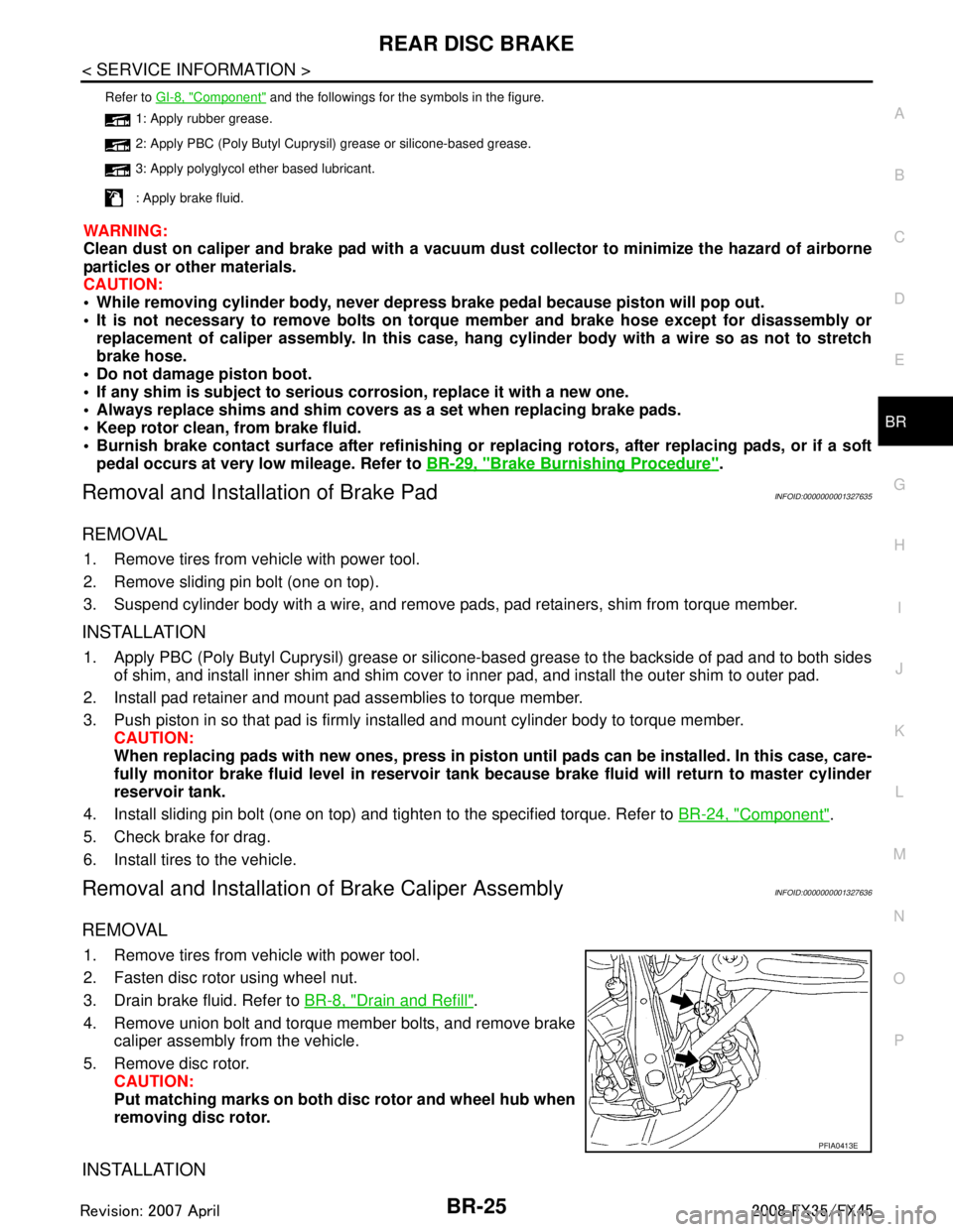
4. Remove union bolt and torque member bolts, and remove brake caliper assembly from the vehicle.
5. Remove disc rotor. CAUTION:
Put matching marks on both disc rotor and wheel hub when
removing disc rotor.
INSTALLATION
Refer to GI-8, "Component" and the followings for the symbols in the figure.
1: Apply rubber grease.
2: Apply PBC (Poly Butyl Cuprysil) grease or silicone-based grease.
3: Apply polyglycol ether based lubricant.
: Apply brake fluid.
PFIA0413E
3AA93ABC3ACD3AC03ACA3AC03AC63AC53A913A773A893A873A873A8E3A773A983AC73AC93AC03AC3
3A893A873A873A8F3A773A9D3AAF3A8A3A8C3A863A9D3AAF3A8B3A8C
Page 1010 of 3924
BR-26
< SERVICE INFORMATION >
REAR DISC BRAKE
CAUTION:
Refill with new brake fluid “DOT 3”.
Do not reuse drained brake fluid.
1. Install disc rotor.CAUTION:
Align the matching marks of disc rotor and wheel hub, which were marked at the time of removal
when reusing disc rotor.
2. Install caliper assembly to the vehicle, and tighten bolts to the specified torque. Refer to BR-24, "
Compo-
nent".
CAUTION:
Before installing caliper assembly to the vehicle , wipe off oil and grease on washer seats on axle
assembly and mounting surface of caliper assembly.
3. Install brake hose to caliper assembly and tighten union bolt to the specified torque. Refer to BR-24,
"Component".
CAUTION:
Do not reuse copper washer for union bolts.
Securely install brake hose to protrusion on caliper assembly.
4. After installing caliper assembly, refill with new brake fluid and bleed air. Refer to BR-8, "
Bleeding Brake
System".
5. Install tires to the vehicle.
Disassembly and Assembly of Brake Caliper AssemblyINFOID:0000000001327637
NOTE:
Do not remove torque member, brake pads, shims, shim cover and pad retainers, when disassembling or
assembling cylinder body.
DISASSEMBLY
1. Remove sliding pin bolts, and then remove brake pads, shims, shim cover, and pad retainer from torque
member and cylinder.
CAUTION:
Do not drop brake pads, shims, shim cover and pad retainer from torque member.
2. Remove sliding pin boot from torque member.
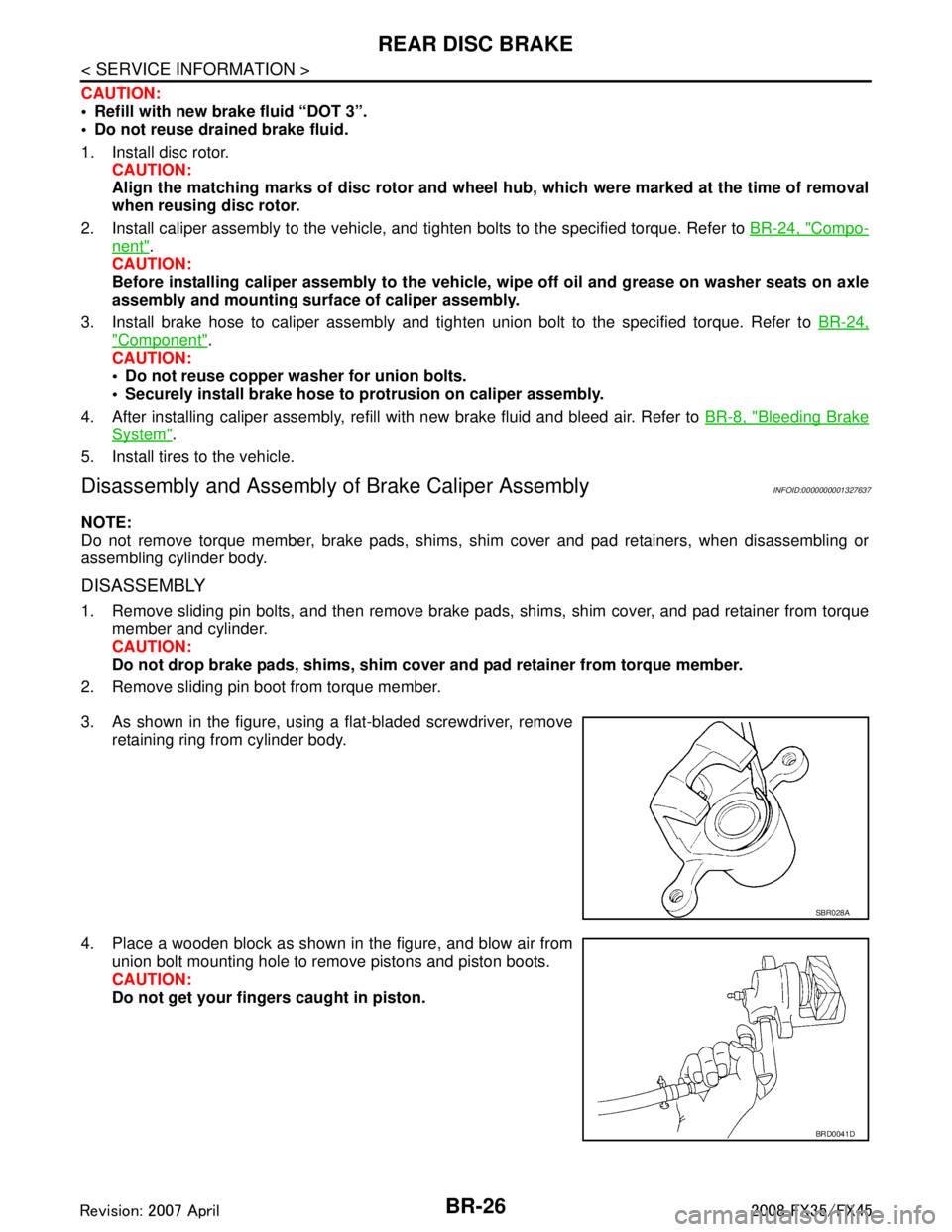
3. As shown in the figure, using a flat-bladed screwdriver, remove retaining ring from cylinder body.
4. Place a wooden block as shown in the figure, and blow air from union bolt mounting hole to remove pistons and piston boots.
CAUTION:
Do not get your fingers caught in piston.
SBR028A
BRD0041D
3AA93ABC3ACD3AC03ACA3AC03AC63AC53A913A773A893A873A873A8E3A773A983AC73AC93AC03AC3
3A893A873A873A8F3A773A9D3AAF3A8A3A8C3A863A9D3AAF3A8B3A8C
Page 1012 of 3924
BR-28
< SERVICE INFORMATION >
REAR DISC BRAKE
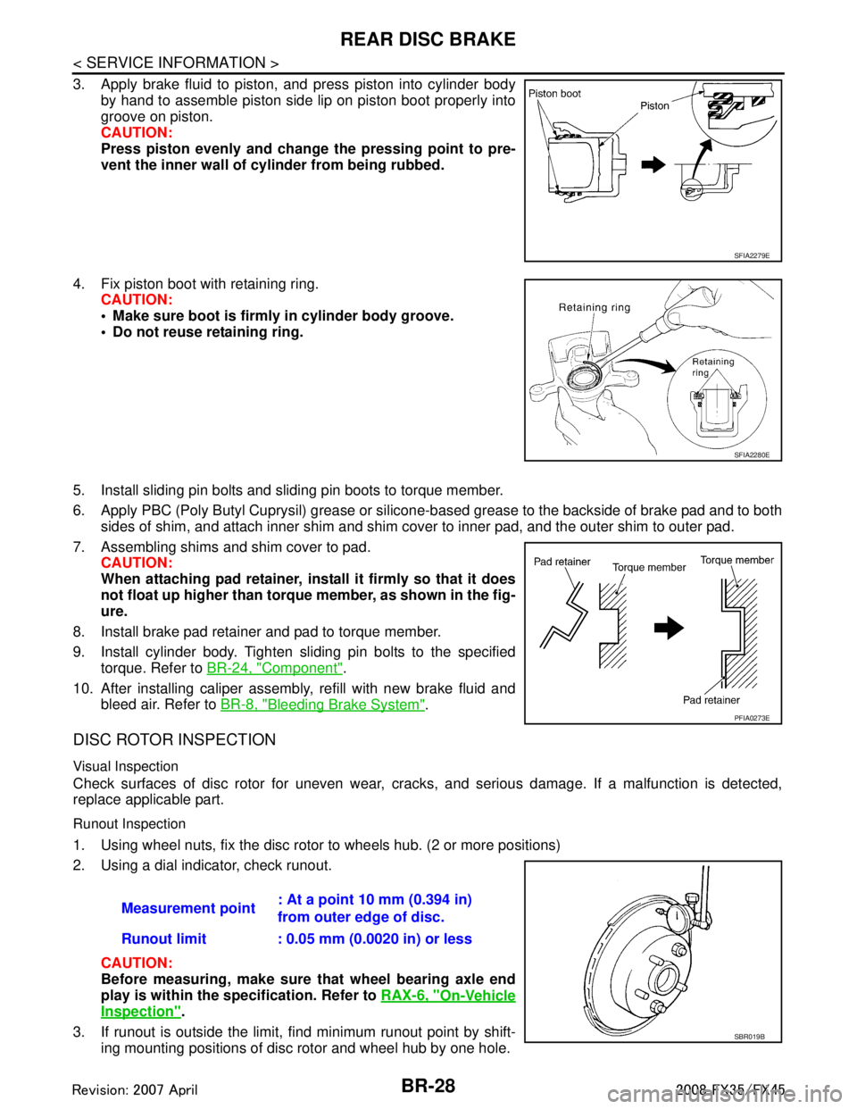
3. Apply brake fluid to piston, and press piston into cylinder bodyby hand to assemble piston side lip on piston boot properly into
groove on piston.
CAUTION:
Press piston evenly and change the pressing point to pre-
vent the inner wall of cylinder from being rubbed.
4. Fix piston boot with retaining ring. CAUTION:
Make sure boot is firmly in cylinder body groove.
Do not reuse retaining ring.
5. Install sliding pin bolts and sliding pin boots to torque member.
6. Apply PBC (Poly Butyl Cuprysil) grease or silicone- based grease to the backside of brake pad and to both
sides of shim, and attach inner shim and shim cover to inner pad, and the outer shim to outer pad.
7. Assembling shims and shim cover to pad. CAUTION:
When attaching pad retainer, inst all it firmly so that it does
not float up higher than torque member, as shown in the fig-
ure.
8. Install brake pad retainer and pad to torque member.
9. Install cylinder body. Tighten sliding pin bolts to the specified torque. Refer to BR-24, "
Component".
10. After installing caliper assembly, refill with new brake fluid and bleed air. Refer to BR-8, "
Bleeding Brake System".
DISC ROTOR INSPECTION
Visual Inspection
Check surfaces of disc rotor for uneven wear, cra cks, and serious damage. If a malfunction is detected,
replace applicable part.
Runout Inspection
1. Using wheel nuts, fix the disc rotor to wheels hub. (2 or more positions)
2. Using a dial indicator, check runout.
CAUTION:
Before measuring, make sure that wheel bearing axle end
play is within the specification. Refer to RAX-6, "
On-Vehicle
Inspection".
3. If runout is outside the limit, find minimum runout point by shift- ing mounting positions of disc rotor and wheel hub by one hole.
SFIA2279E
SFIA2280E
PFIA0273E
Measurement point : At a point 10 mm (0.394 in)
from outer edge of disc.
Runout limit : 0.05 mm (0.0020 in) or less
SBR019B
3AA93ABC3ACD3AC03ACA3AC03AC63AC53A913A773A893A873A873A8E3A773A983AC73AC93AC03AC3
3A893A873A873A8F3A773A9D3AAF3A8A3A8C3A863A9D3AAF3A8B3A8C