Page 217 of 281

Downloaded from www.Manualslib.com manuals search engine GWFLORID Maintenance Manual210
Electromagnetic Clutch
Clutch composition
Electromagnetic clutch consists of an armature, a solenoid,
and a pulley.
Areas of importance during clutch usage
B e c a u s e t h e j o i n t o f t h e e l e c t r o m a g n e t i c c l u t c h
operates under high speeds, separation-joint marks on
the pulley and armature are completely normal, and do
not harm clutch usage.
The clutch's operating voltage must be consistent with
the specified voltage rating. Too high or too low will
affect its normal usage.
The clearance between the coil and the pulley is
very important. If too big, the effect of the magnetic
field reduces. If too small, the high speed pulley rubs
against the fixed coil, causing the clutch to burn.
The clearance between the armature and the pulley
is also very important. If too big, it leads to insufficient
clutch pull-in force. If too small, it may cause armature
damage.
Clutch removal
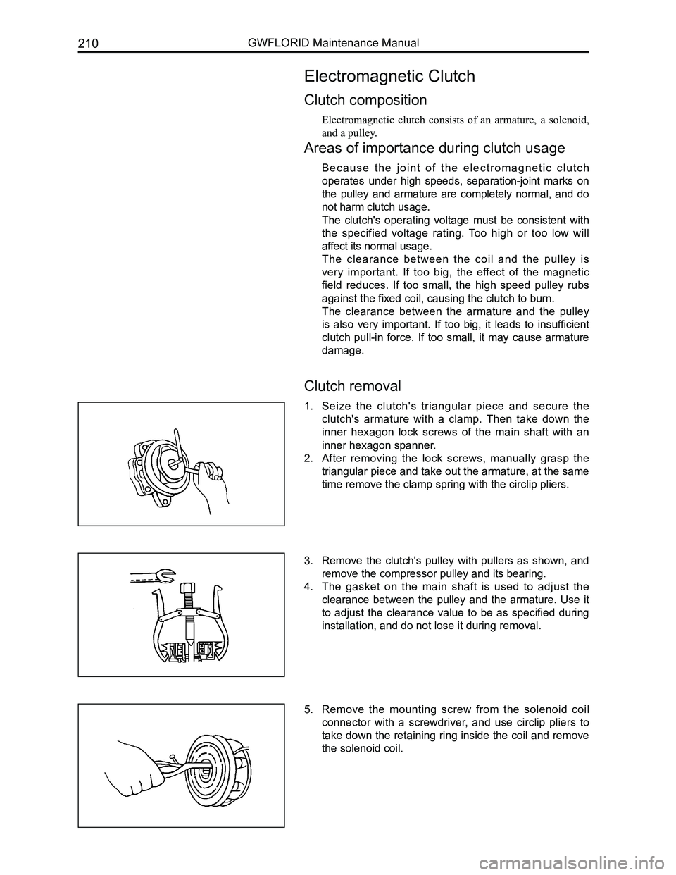
1. Seize the clutch's triangular piece and secure the
clutch's armature with a clamp. Then take down the
inner hexagon lock screws of the main shaft with an
inner hexagon spanner.
2. After removing the lock screws, manually grasp the
triangular piece and take out the armature, at the same
time remove the clamp spring with the circlip pliers.
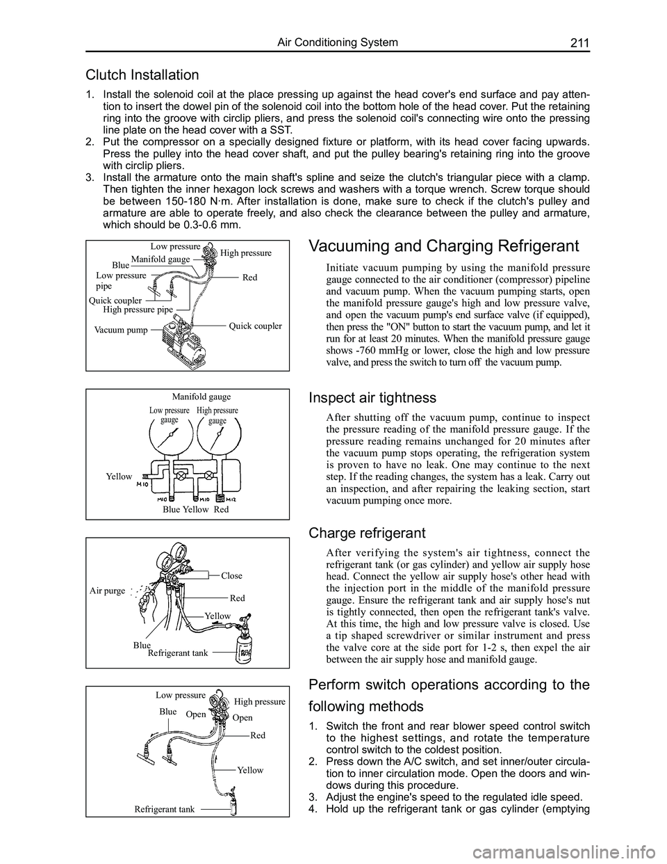
3. Remove the clutch's pulley with pullers as shown, and
remove the compressor pulley and its bearing.
4. The gasket on the main shaft is used to adjust the
clearance between the pulley and the armature. Use it
to adjust the clearance value to be as specified during
installation, and do not lose it during removal.
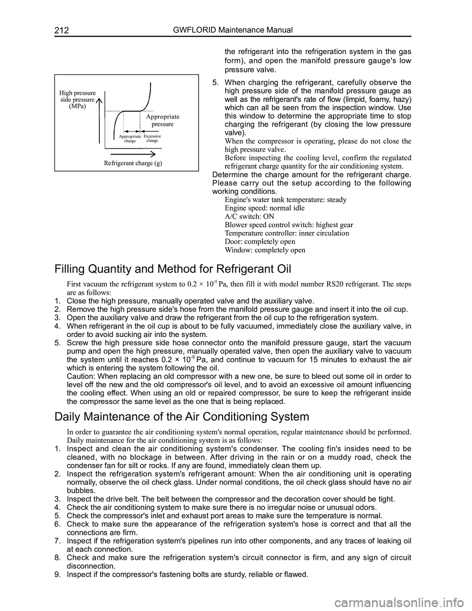
5. Remove the mounting screw from the solenoid coil
connector with a screwdriver, and use circlip pliers to
take down the retaining ring inside the coil and remove
the solenoid coil.
Page 218 of 281

Downloaded from www.Manualslib.com manuals search engine 211Air Conditioning System
Clutch Installation
1. Install the solenoid coil at the place pressing up against the head cover's end surface and pay atten-
tion to insert the dowel pin of the solenoid coil into the bottom hole of the head cover. Put the retaining
ring into the groove with circlip pliers, and press the solenoid coil's connecting wire onto the pressing
line plate on the head cover with a SST.
2. Put the compressor on a specially designed fixture or platform, with its head cover facing upwards.
Press the pulley into the head cover shaft, and put the pulley bearing's retaining ring into the groove
with circlip pliers.
3. Install the armature onto the main shaft's spline and seize the clutch's triangular piece with a clamp.
Then tighten the inner hexagon lock screws and washers with a torque wrench. Screw torque should
be between 150-180 N·m. After installation is done, make sure to check if the clutch's pulley and
armature are able to operate freely, and also check the clearance between the pulley and armature,
which should be 0.3-0.6 mm.
Vacuuming and Charging Refrigerant
Initiate vacuum pumping by using the manifold pressure
gauge connected to the air conditioner (compressor) pipeline
and vacuum pump. When the vacuum pumping starts, open
the manifold pressure gauge's high and low pressure valve,
and open the vacuum pump's end surface valve (if equipped),
then press the "ON" button to start the vacuum pump, and let it
run for at least 20 minutes. When the manifold pressure gauge
shows -760 mmHg or lower, close the high and low pressure
valve, and press the switch to turn off the vacuum pump.
Low pressure gaugeHigh pressure gauge
Manifold gauge
Yellow
BlueYellowRed
Air purge
Blue
Yellow
Red
Close
Refrigerant tank
Refrigerant tank
Blue
Red
Yellow
Low pressureHigh pressure
OpenOpen
Quick coupler
Red
Manifold gauge
Low pressure pipe
Quick couplerHigh pressure pipe
Vacuum pump
Low pressureHigh pressure
Blue
Inspect air tightness
After shutting off the vacuum pump, continue to inspect
the pressure reading of the manifold pressure gauge. If the
pressure reading remains unchanged for 20 minutes after
the vacuum pump stops operating, the refrigeration system
is proven to have no leak. One may continue to the next
step. If the reading changes, the system has a leak. Carry out
an inspection, and after repairing the leaking section, start
vacuum pumping once more.
Charge refrigerant
After verifying the system's air tightness, connect the
refrigerant tank (or gas cylinder) and yellow air supply hose
head. Connect the yellow air supply hose's other head with
the injection port in the middle of the manifold pressure
gauge. Ensure the refrigerant tank and air supply hose's nut
is tightly connected, then open the refrigerant tank's valve.
At this time, the high and low pressure valve is closed. Use
a tip shaped screwdriver or similar instrument and press
the valve core at the side port for 1-2 s, then expel the air
between the air supply hose and manifold gauge.
Perform switch operations according to the
following methods
1. Switch the front and rear blower speed control switch
to the highest settings, and rotate the temperature
control switch to the coldest position.
2. Press down the A/C switch, and set inner/outer circula-
tion to inner circulation mode. Open the doors and win-
dows during this procedure.
3. Adjust the engine's speed to the regulated idle speed.
4. Hold up the refrigerant tank or gas cylinder (emptying
Page 219 of 281

Downloaded from www.Manualslib.com manuals search engine GWFLORID Maintenance Manual212
High pressure side pressure(MPa)
Appropriate pressure
Appropriate chargeExcessive charge
Refrigerant charge (g)
5. When charging the refrigerant, carefully observe the
high pressure side of the manifold pressure gauge as
well as the refrigerant's rate of flow (limpid, foamy, hazy)
which can all be seen from the inspection window. Use
this window to determine the appropriate time to stop
charging the refrigerant (by closing the low pressure
valve).
When the compressor is operating, please do not close the
high pressure valve.
Before inspecting the cooling level, confirm the regulated
refrigerant charge quantity for the air conditioning system.
Determine the charge amount for the refrigerant charge.
Please carry out the setup according to the following
working conditions.
Engine's water tank temperature: steady
Engine speed: normal idle
A/C switch: ON
Blower speed control switch: highest gear
Temperature controller: inner circulation
Door: completely open
Window: completely open
Filling Quantity and Method for Refrigerant Oil
First vacuum the refrigerant system to 0.2 × 10⁻⁵ Pa, then fill it with model number RS20 refrigerant. The steps
are as follows:
1. Close the high pressure, manually operated valve and the auxiliary valve\
.
2. Remove the high pressure side's hose from the manifold pressure gauge an\
d insert it into the oil cup.
3. Open the auxiliary valve and draw the refrigerant from the oil cup to th\
e refrigeration system.
4. When refrigerant in the oil cup is about to be fully vacuumed, immediately close the auxiliary valve, in
order to avoid sucking air into the system.
5. Screw the high pressure side hose connector onto the manifold pressure gauge, start the vacuum
pump and open the high pressure, manually operated valve, then open the auxiliary valve to vacuum
the system until it reaches 0.2 × 10⁻⁵ Pa, and continue to vacuum for 15 minutes to exhaust the air
which is entering the system following the oil.
Caution: When replacing an old compressor with a new one, be sure to bleed out some oil in order to
level off the new and the old compressor's oil level, and to avoid an excessive oil amount influencing
the cooling effect. When using an old or repaired compressor, be sure to keep the refrigerant inside
the compressor the same level as the one that is being replaced.
Daily Maintenance of the Air Conditioning System
In order to guarantee the air conditioning system's normal operation, regular maintenance should be performed.
Daily maintenance for the air conditioning system is as follows:
1. Inspect and clean the air conditioning system's condenser. The cooling fin's insides need to be
cleaned, with no blockage in between. After driving in the rain or on a muddy road, check the
condenser fan for silt or rocks. If any are found, immediately clean the\
m up.
2. Inspect the refrigeration system's refrigerant amount: When the air conditioning unit is operating
normally, observe the oil check glass. Under normal conditions, the oil check glass should have no air
bubbles.
3. Inspect the drive belt. The belt between the compressor and the decoration cover should be tight\
.
4. Check the air conditioning system to make sure there is no irregular noi\
se or unusual odors.
5. Check the compressor's inlet and exhaust port areas to make sure the tem\
perature is normal.
6. Check to make sure the appearance of the refrigeration system's hose is correct and that all the
connections are firm.
7. Inspect if the refrigeration system's pipelines run into other components, and any traces of leaking oil
at each connection.
8. Check and make sure the refrigeration system's circuit connector is firm, and any sign of circuit
disconnection.
9. Inspect if the compressor's fastening bolts are sturdy, reliable or flawed.
the refrigerant into the refrigeration system in the gas
form), and open the manifold pressure gauge's low
pressure valve.
Page 220 of 281
Downloaded from www.Manualslib.com manuals search engine 213Airbags
Airbags
Airbag Electronic Control Unit ..........................................214
Diagnostic Scanner ..........................................................215
Troubleshooting ................................................................216
Vehicle Collision Diagnostics ............................................226
Removal Method for Individual Components....................227
Driver Side Airbag Module (DAB), Front Passenger Side
Airbag Module (PAB), Clock Spring, and Steering Wheel ....228
Airbag Module Disposal....................................................230
Airbag’s Diagnostic Methods Without a
Diagnostic Scanner ..........................................................232
Page 221 of 281

Downloaded from www.Manualslib.com manuals search engine GWFLORID Maintenance Manual214
Areas of Importance
1. While performing maintenance on the SRS airbag, make sure to work in accordance with this
chapter's steps and notes.
2. Be sure to use the specified test apparatus and SST (Special Service Tools) which are mentioned in this
chapter.
3. While performing maintenance on the following mentioned components, if there is any problem with a
component, be sure to replace it with a new one.
• Airbag ECU assembly.
• Clock spring assembly.
• Driver side airbag assembly.
• Front passenger side airbag module.
• Driver side preload seat belt.
• Front passenger side preload seat belt.
• Airbag wire harness.
4. While performing maintenance, please disconnect the battery's negative terminal connector, and then
after waiting for 60 s, commence operation. Furthermore, wrap up the removed negative terminal with
insulating tape.
After the battery power is cut off, the capacitor in the airbag ECU will still maintain a set amount of electrical
energy. If used without waiting a sufficient amount of time, it may lead to serious injury and accidents due to
the airbag's faulty deployment.
5. When painting the vehicle, excessive heat may influence the components, in which case the SRS-ECU,
airbag module, clock spring, etc., should first be removed and set aside\
.
Use a diagnostic scanner to clear the trouble code after the SRS airbag is repaired, as to ensure the warning
lamp will continue to work normaly.
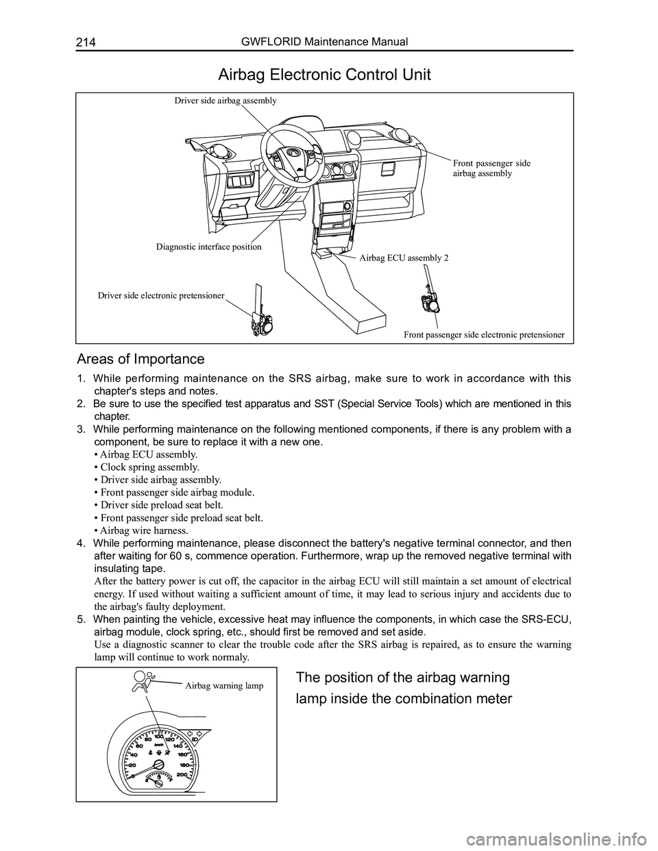
Airbag Electronic Control Unit
Airbag warning lamp
Airbag ECU assembly 2
Front passenger side airbag assembly
Driver side airbag assembly
Diagnostic interface position
Driver side electronic pretensioner
Front passenger side electronic pretensioner
The position of the airbag warning
lamp inside the combination meter
Page 222 of 281
Downloaded from www.Manualslib.com manuals search engine 215Airbags
Airbag electronic control interface and interface-pin definition
No. NameDescription
1DRV A/B + Driver side airbag assembly, high end
2DRV A/B -Driver side airbag assembly, low end
3PSG A/B +Front passenger side airbag assembly, high end
4PSG A/B -Front passenger side airbag assembly, low end
7PSG PRETENSIONER -Front passenger seat belt pretensioner, low end
8DRV PRETENSIONER +Driver seat belt pretensioner, high end
9DRV PRETENSIONER -Driver seat belt pretensioner, low end
10WARNING LAMPWarning lamp
11GNDGround cable
25BPT Hi ON power supply
30PSG PRETENSIONER -Front passenger seat belt pretensioner, high end
46K-LINESerial data I/O (K wire) diagnosis
Diagnostic Scanner
InstrumentNameApplication
X-431 diagnostic scannerCheck the system malfunction
of the SRS airbag system and
clear the ECU trouble code.
Page 223 of 281

Downloaded from www.Manualslib.com manuals search engine GWFLORID Maintenance Manual216
SRS airbag warning lamp inspection
1. When the ignition switch is set to the ON position, check if the SRS warning lamp remains on for 6-7 s.
2. If the SRS warning lamp shuts off after 6-7 s, this is normal.
3. Except for the items listed above, diagnostic inspection is still needed\
.
System diagnosis
Airbag ECU will initiate a series of diagnostic test cycles to check if the airbag system functions are ready for
use. This diagnostic test can guard against the restraint system's faulty execution and at the same time guarantee
prompt execution in a collision. If a malfunction appears, airbag ECU will store the appropriate trouble code and
light up the warning lamp to point out the malfunction, as to make maint\
enance more convenient.
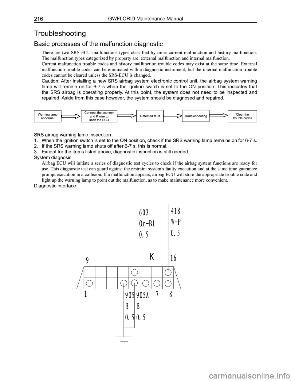
Diagnostic interface
Troubleshooting
Basic processes of the malfunction diagnostic
There are two SRS-ECU malfunctions types classified by time: current malfunction and history malfunction.
The malfunction types categorized by property are: external malfunction \
and internal malfunction.
Current malfunction trouble codes and history malfunction trouble codes may exist at the same time. External
malfunction trouble codes can be eliminated with a diagnostic instrument, but the internal malfunction trouble
codes cannot be cleared unless the SRS-ECU is changed.
Caution: After installing a new SRS airbag system electronic control unit, the airbag system warning
lamp will remain on for 6-7 s when the ignition switch is set to the ON position. This indicates that
the SRS airbag is operating properly. At this point, the system does not need to be inspected and
repaired. Aside from this case however, the system should be diagnosed and repaired.
Warning lampabnormal
Connect the scannerand K wire to scan the ECUDetected faultTroubleshooting Clear the trouble codes
Page 224 of 281

Downloaded from www.Manualslib.com manuals search engine 217Airbags
Malfunction judgment
1. Malfunction record (trouble code storage)
After the ECU performs the diagnostic test cycle in order to verify a malfunction, the SRS-ECU will store the
relevant code, the initial detection time, the final detection time, and the number of times it occurred in the
EEPROM.
The SRS-ECU can store 16 codes at most.
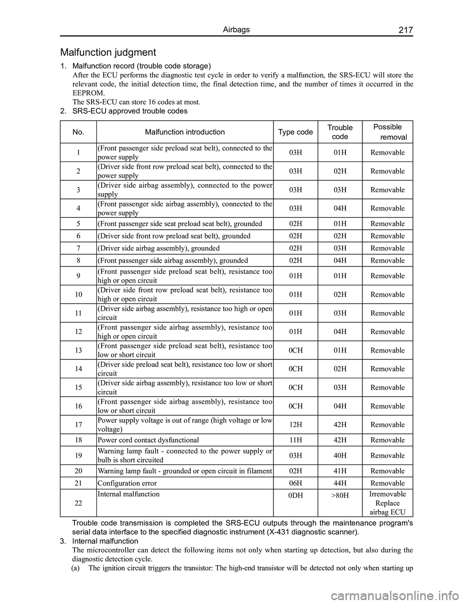
2. SRS-ECU approved trouble codes
No.Malfunction introductionType codeTrouble
code
Possible
removal
1(Front passenger side preload seat belt), connected to the
power supply03H01HRemovable
2(Driver side front row preload seat belt), connected to the
power supply03H02HRemovable
3(Driver side airbag assembly), connected to the power
supply03H03HRemovable
4(Front passenger side airbag assembly), connected to the
power supply03H04HRemovable
5(Front passenger side seat preload seat belt), grounded02H01HRemovable
6(Driver side front row preload seat belt), grounded02H02HRemovable
7(Driver side airbag assembly), grounded02H03HRemovable
8(Front passenger side airbag assembly), grounded02H04HRemovable
9(Front passenger side preload seat belt), resistance too
high or open circuit01H01HRemovable
10(Driver side front row preload seat belt), resistance too
high or open circuit01H02HRemovable
11(Driver side airbag assembly), resistance too high or open
circuit01H03HRemovable
12(Front passenger side airbag assembly), resistance too
high or open circuit01H04HRemovable
13(Front passenger side preload seat belt), resistance too
low or short circuit0CH01HRemovable
14(Driver side preload seat belt), resistance too low or short
circuit0CH02HRemovable
15(Driver side airbag assembly), resistance too low or short
circuit0CH03HRemovable
16(Front passenger side airbag assembly), resistance too
low or short circuit0CH04HRemovable
17Power supply voltage is out of range (high voltage or low
voltage)12H42HRemovable
18Power cord contact dysfunctional11H42HRemovable
19Warning lamp fault - connected to the power supply or
bulb is short circuited03H40HRemovable
20Warning lamp fault - grounded or open circuit in filament02H41HRemovable
21Configuration error06H44HRemovable
22
Internal malfunction0DH>80HIrremovable
Replace
airbag ECU
Trouble code transmission is completed the SRS-ECU outputs through the maintenance program's
serial data interface to the specified diagnostic instrument (X-431 dia\
gnostic scanner).
3. Internal malfunction
The microcontroller can detect the following items not only when starting up detection, but also during the
diagnostic detection cycle.
(a) The ignition circuit triggers the transistor: The high-end transistor will be detected not only when starting up