Page 121 of 281

Downloaded from www.Manualslib.com manuals search engine GWFLORID Maintenance Manual114
(d) Measure the front hub bearing's starting torque.
Put the SST on the wheel bolts which are at the symmetric
locations. Put a dial torque wrench on the SST to slowly
rotate the flange assembly (45°/4s), requiring a starting
torque range of 0.1-0.3 N·m.
If the bearing rotation is not flexible, the front hub flange
plate surface movement inaccurate, or front hub bearing
starting torque is too much. The assembly must be replaced.
Steering knuckle's front hub bearing and
front hub flange assembly
1. Removal and inspection of front hub flange assembly.
(a) Use SST like a hand held travel hammer to repeatedly
hammer off the front hub flange assembly from the
steering knuckle and front hub bearing. Remove the
front hub with bearing's inner ring.
(b) Remove the bearing's inner ring on the front hub.
Use SST to remove the bearing's inner ring.
SST
SST
Bearing inner ring
SST
(c) Use dye penetrant to inspect the front hub flange for
cracks, which should be replaced if found.
(d) If one would like to continue using the front hub flange
assembly, first inspect the dimensions for the mounting
area of the bearing for inaccurate dimensions. If
oversized, replace.
Measurement range: Φ38+0.025 +0.009 mm
2. Remove the steering knuckle's front hub bearing.
3. Remove the snap ring for hole 72.
Use a bent nose retaining ring caliper for holes to remove the
snap ring for hole 72.
Page 122 of 281

Downloaded from www.Manualslib.com manuals search engine 115Brake System
4. Replace the removed bearing's inner ring back to the
bearing's original position.
5. Press out the front hub bearing from inside of the steer-
ing knuckle.
On the press, withstand the bearing inner ring that was put
on with SST, and press out the entire front hub bearing.
Caution: The front hub bearing assembly is a disposable
part, which needs to be replaced with a new one.
Steering knuckle and hub brake assembly
installation
1. On the press, press the front hub bearing assembly
into the steering knuckle hole bearing mounting posi-
tion with SST.
SST
SST
SST
6. If the steering knuckle has no cracks and one would
like to continue to use it, first inspect the bearing's
mounting location dimensions of the steering knuckle's
inner hole. If the measurements are oversized, replace
the steering knuckle.
Measurement range: Φ71-0.032 -0.062 mm
2. Press the front hub flange assembly.
On the press, press the front hub flange into the front hub
bearing mounting position using SST.
SST
SST
Page 123 of 281

Downloaded from www.Manualslib.com manuals search engine GWFLORID Maintenance Manual116
3. Examine the front hub flange plate surface runout.
Examining methods are the same as the methods used
during disassembly. Plate surface runout should not exceed
0.03 mm.
4. Examine the front hub bearing assembly's starting
torque.
Examining methods are the same as the methods used during
disassembly. Put the SST on the wheel bolts which are at the
symmetrical locations. Put a dial torque wrench on the SST to
slowly rotate the flange's flange assembly (45°/4s), which re-
quires a starting torque range of 0.1-0.3 N·m
5. Install the snap ring for hole 72.
Use a bent nose retaining ring caliper for holes to install the
snap ring for hole 72 at the steering knuckle's retaining ring
mounting position.
6. Install the steering knuckle's front hub bearing and
front hub flange assembly.
7. Install the front brake disc cover.
Install the front brake disc cover on the steering knuckle, and
tighten the bolt to the set torque.
Tightening torque: 9±2 N·m
SST
8. Install the front brake disc.
Page 124 of 281
Downloaded from www.Manualslib.com manuals search engine 117Brake System
9. Examine the front brake disc plate surface runout.
When measuring, tighten the two wheel nut's symmetrical
locations. The front brake disc's brake linings runout on the
two sides should be less than 0.11 mm.
10. Install the brake caliper assembly.
Install the brake caliper on the steering knuckle, and tighten
the bolt according to the set torque.
Tightening torque: 100±10 N·m
Page 125 of 281

Downloaded from www.Manualslib.com manuals search engine GWFLORID Maintenance Manual118
Front Brake Caliper
Components
Disposable parts
Inner and outer brake pad assembly re-
placement
Remark: When applying the brake while driving, if the front
tires makes a continuous screeching sound, inspect the inner
and outer brake pad and friction limit alarm plate. If there
are traces of rubbing from the brake disc on the alarm plate,
the inner and outer brake pad assembly should be replaced.
1. Remove the front wheel.
2. Inspect the inner and outer brake pad's friction material
thickness.
By looking through the caliper's observation ports, inspect
the inner and outer brake pad friction material thickness. If it
is no longer within the specified range, it should be replaced.
Minimum thickness: 2.0 mm
Bleed screw cap
Air bleed screw
Caliper
Rectangular sealing ring
Piston
P iston dust cover
Inner muffler plate subassembly
Alarm plate
Inner brake pad assembly
Outer brake pad assembly
Outer muffler plate subassembly
Guide pin
Guide pin dust cover
Caliper frame
Brake block yoke spring plate
30 ± 5
: Specified torqueN·m
10 ± 2
Q1840820
Rubber grease
Page 126 of 281

Downloaded from www.Manualslib.com manuals search engine 119Brake System
3. Remove the caliper assembly.
(a) Remove the hexagon bolt for flange face connecting
the caliper and caliper frame's lower end.
(b) Lift the caliper assembly and use a rope to hang it up to
protect the brake pipeline.
Remark: Do not unscrew the brake pipeline and bleed screw.
4. Remove the following parts.
(a) The group of inner and outer shims B.
(b) The group of inner and outer shims A.
(c) The group of inner and outer brake discs.
(d) One pair of yoke springs.
5. Measure the brake disc thickness.
(See steering knuckle and hub brake assembly examination and
disassembly step 4).
6. Measure the brake disc radial runout.
(See steering knuckle and hub brake assembly examination and
disassembly step 3).
7. Install the yoke spring.
Install the brake block yoke spring plate to the caliper frame.
Outer shim B
Outer shim AInner brake disc
Warning device
Inner shim B
Inner shim A
Outer brake disc
Yoke spring
Page 127 of 281

Downloaded from www.Manualslib.com manuals search engine GWFLORID Maintenance Manual120
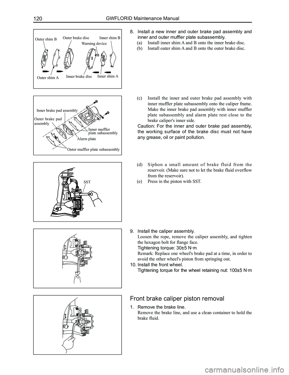
8. Install a new inner and outer brake pad assembly and
inner and outer muffler plate subassembly.
(a) Install inner shim A and B onto the inner brake disc.
(b) Install outer shim A and B onto the outer brake disc.
(c) Install the inner and outer brake pad assembly with
inner muffler plate subassembly onto the caliper frame.
Make the inner brake pad assembly with inner muffler
plate subassembly and alarm plate rest close to the
brake caliper's inner side.
Caution: For the inner and outer brake pad assembly,
the working surface of the brake disc must not have
any grease, oil or paint pollution.
(d) S i p h o n a s m a l l a m o u n t o f b r a k e f l u i d f r o m t h e
reservoir. (Make sure not to let the brake fluid overflow
from the reservoir).
(e) Press in the piston with SST.
9. Install the caliper assembly.
Loosen the rope, remove the caliper assembly, and tighten
the hexagon bolt for flange face.
Tightening torque: 30±5 N·m
Remark: Replace one wheel's brake pad at a time, in order to
avoid the other wheel's piston from springing out.
10. Install the front wheel.
Tightening torque for the wheel retaining nut: 100±5 N·m
Front brake caliper piston removal
1. Remove the brake line.
Remove the brake line, and use a clean container to hold the
brake fluid.
SST
Outer shim B
Outer shim AInner brake disc
Warning device
Inner shim B
Inner shim A
Outer brake disc
Inner muffler plate subassembly
Alarm plate
Inner brake pad assembly
Outer brake pad assembly
Outer muffler plate subassembly
Page 128 of 281

Downloaded from www.Manualslib.com manuals search engine 121Brake System
2. Remove the caliper assembly.
(a) Remove the two hexagon bolts for flange face connecting
the caliper and caliper frame.
(b) Remove the caliper assembly from the caliper frame.
3. Remove the following parts.
(a) The group of inner and outer shims B.
(b) The group of inner and outer shims A.
(c) The group of inner and outer brake discs.
(d) One pair of yoke springs.
4. Remove the piston and piston dust cover from the
caliper.
(a) Place a block in the middle of the caliper.
(b) Use an airgun or air pipe to align the brake pipeline
holes. Remove the piston from the caliper, and at the
same time remove the piston dust cover.
(c) Use a clean rag or other soft cloth to extract the piston.
Warning: When using compressed air, be sure not to
place fingers in front of the piston.
5. Remove the rectangular sealing ring from the caliper.
Use a paperclip to remove the rectangular sealing ring from
the caliper.
Caution: The tools being used should not be sharp, in
order to avoid tearing the rectangular sealing ring.
Inner and outer brake pad assembly exami-
nation
Measure the inner and outer brake pad assembly's thickness.
Standard thickness: 8.5 mm
Minimum thickness: 2.0 mm
If it is smaller than the minimum level of thickness or there
are traces of uneven wear and tear, the brake pad should be
replaced.