2008 GREAT WALL FLORID bulb
[x] Cancel search: bulbPage 211 of 281

Downloaded from www.Manualslib.com manuals search engine GWFLORID Maintenance Manual204
FailureSymptoms Cause analysis
Air con-
ditioning
system fails
to produce
cold air
Compressor
does not work
Blown fuse, compressor relay damaged
Pressure switch contact broken, short circuited, or open circuit
Compressor electromagnetic clutch open circuit
Switch burnt out
Main relay burnt out
Clutch slips
Compressor belt broken or loose
Compressor failure
Insufficient coolant, system pressure below 0.196 MPa
System pressure exceeds 3.14 MPa
Engine water temperature is too high
Clutch voltage is below 7 V
Compressor
pulling in
Compressor relay often open contact bond, system coolant leaks severely,
system has no coolant
Blower does not work
Blower has no windBlown fuse
Blower motor brush damaged
Blower switch damaged
Wiring connector detached or open circuit
Speed regulation module damaged
Blower has no wind at high speeds, high speed relay damaged
Note: Blower's non operational process has a resistance value of 0, with a
open circuit resistance value of
The cool-
ing system
sometimes
works, some-
times not
Compressor operates
normally
Cooling system has ice blockage
Thermistor or thermometer bulb malfunction
Abnormal A/C switch contact
Condenser blower damaged
Compressor operates
abnormally
Clutch slides, clutch coil loose, clutch coil bad connection
Insufficient
cooling
Low wind volume
Blower fan normal: air pipe damaged
Cooling fan operates abnormally:
(1) Blower switch abnormal
(2) Supply voltage low
(3) Speed regulation module damaged
Wind vol-
ume normal
Compressor operates normally
(1) High and low pressure side's pressure is low
(a) Expansion valve is blocked
(b) Expansion valve opening is too small
(2) High and low pressure pipe's pressure is high
(a) High pressure pipeline malfunction, uneven flow
(b) Thermistor failure
(c) Expansion valve opening is too big
(d) Too much refrigerant oil
(e) Too much refrigerant
(f) Poor condenser heat dissipation
Note: When the speed is at 2000 r/min, cooling fan at max gear, and air tem-
perature at 30-35oC, the system's low pressure side pressure should be 147-
192 KPa, and high pressure side pressure 1373-1668 KPa
Troubleshooting
Page 224 of 281

Downloaded from www.Manualslib.com manuals search engine 217Airbags
Malfunction judgment
1. Malfunction record (trouble code storage)
After the ECU performs the diagnostic test cycle in order to verify a malfunction, the SRS-ECU will store the
relevant code, the initial detection time, the final detection time, and the number of times it occurred in the
EEPROM.
The SRS-ECU can store 16 codes at most.
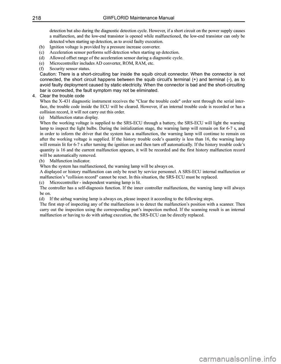
2. SRS-ECU approved trouble codes
No.Malfunction introductionType codeTrouble
code
Possible
removal
1(Front passenger side preload seat belt), connected to the
power supply03H01HRemovable
2(Driver side front row preload seat belt), connected to the
power supply03H02HRemovable
3(Driver side airbag assembly), connected to the power
supply03H03HRemovable
4(Front passenger side airbag assembly), connected to the
power supply03H04HRemovable
5(Front passenger side seat preload seat belt), grounded02H01HRemovable
6(Driver side front row preload seat belt), grounded02H02HRemovable
7(Driver side airbag assembly), grounded02H03HRemovable
8(Front passenger side airbag assembly), grounded02H04HRemovable
9(Front passenger side preload seat belt), resistance too
high or open circuit01H01HRemovable
10(Driver side front row preload seat belt), resistance too
high or open circuit01H02HRemovable
11(Driver side airbag assembly), resistance too high or open
circuit01H03HRemovable
12(Front passenger side airbag assembly), resistance too
high or open circuit01H04HRemovable
13(Front passenger side preload seat belt), resistance too
low or short circuit0CH01HRemovable
14(Driver side preload seat belt), resistance too low or short
circuit0CH02HRemovable
15(Driver side airbag assembly), resistance too low or short
circuit0CH03HRemovable
16(Front passenger side airbag assembly), resistance too
low or short circuit0CH04HRemovable
17Power supply voltage is out of range (high voltage or low
voltage)12H42HRemovable
18Power cord contact dysfunctional11H42HRemovable
19Warning lamp fault - connected to the power supply or
bulb is short circuited03H40HRemovable
20Warning lamp fault - grounded or open circuit in filament02H41HRemovable
21Configuration error06H44HRemovable
22
Internal malfunction0DH>80HIrremovable
Replace
airbag ECU
Trouble code transmission is completed the SRS-ECU outputs through the maintenance program's
serial data interface to the specified diagnostic instrument (X-431 dia\
gnostic scanner).
3. Internal malfunction
The microcontroller can detect the following items not only when starting up detection, but also during the
diagnostic detection cycle.
(a) The ignition circuit triggers the transistor: The high-end transistor will be detected not only when starting up
Page 225 of 281

Downloaded from www.Manualslib.com manuals search engine GWFLORID Maintenance Manual218
detection but also during the diagnostic detection cycle. However, if a short circuit on the power supply causes
a malfunction, and the low-end transistor is opened while malfunctioned, the low-end transistor can only be
detected when starting up detection, as to avoid faulty execution.
(b) Ignition voltage is provided by a pressure increase converter.
(c) Acceleration sensor performs self-detection when starting up detection.
(d) Allowed offset range of the acceleration sensor during a diagnostic cycle.
(e) Microcontroller includes AD converter, ROM, RAM, etc.
(f) Security sensor status.
Caution: There is a short-circuiting bar inside the squib circuit connector. When the connector is not
connected, the short circuit happens between the squib circuit's terminal (+) and terminal (-), as to
avoid faulty deployment caused by static electricity. When the connector is bad and the short-circuiting
bar is connected, the fault symptom may not be eliminated.
4. Clear the trouble code
When the X-431 diagnostic instrument receives the "Clear the trouble code" order sent through the serial inter-
face, the trouble code inside the ECU will be cleared. However, if an internal trouble code is recorded or has a
collision record, it will not carry out this order.
(a) Malfunction status display.
When the working voltage is supplied to the SRS-ECU through a battery, the SRS-ECU will light the warning
lamp to inspect the light bulbs. During the initialization stage, the warning lamp will remain on for 6-7 s, and
in order to inform the driver that the system has a malfunction, the warning lamp will continue to remain on
after the working voltage is supplied. If the history trouble code’s quantity is less than 16, the warning lamp
will remain lit for 6-7 s after turning the ignition on and then turn off automatically. If the history trouble code’s
quantity is 16 and the current malfunction appears, it will be recorded and the first history malfunction record
will be automatically removed.
(b) Malfunction indicator.
When the system has malfunctioned, the warning lamp will be always on.
A displayed or history malfunction can only be reset by service personnel. A SRS-ECU internal malfunction or
malfunction’s "collision record" cannot be reset. In this situation, the SRS-ECU mus\
t be replaced.
(c) Microcontroller - independent warning lamp is lit.
The controller has a self-diagnosis function. If the inner controller malfunctions, the warning lamp will always
be on.
(d) If the airbag warning lamp is always on, please inspect it according to the following steps.
The first step of inspecting any of the malfunctions is to detect the malfunction’s position with a scanner. Then
carry out the inspection using the corresponding part’s inspection method. If the scanning result is an internal
malfunction or having to do with airbag execution, the SRS-ECU can be di\
rectly replaced.
Page 226 of 281

Downloaded from www.Manualslib.com manuals search engine 219Airbags
NO.Troubleshooting listExplanation
1Airbag system warning lamp not litAirbag system warns of circuit malfunction
2Airbag system warning lamp is always onAirbag system warns of circuit
malfunction or external malfunction
2. Airbag system warning lamp does not lit
Inspection
statusAirbag system warning lamp does not lit.
Possible
causes
• Voltage disappears (fuse open circuit)
• Combination meter malfunction
• Wire harness malfunction between the instrument cluster and ECU unit
Diagnostic procedures
While performing the first malfunction detection, it is suggested to wiggle the wire harness and plugs to check for
intermittent or poor contact. If there is, please check whether the plugs, terminals, and the wire harness are connected
properly and undamaged. If the above mentioned problems do not exist, pl\
ease take the following steps.
StepsInspectionOperation
1
Detect other wire harness and instrument cluster indicator
lamps
• Set the ignition switch to the ON position
• Are other warning and indicator lamps on?
Yes
Set the ignition switch to the LOCK
position, and then proceed to the
next step
No
Detect the instrument cluster's
power supply system and the
grounded system (fuse)
2
Inspect the light bulbs
Warning:
Incorrect airbag system component operation will cause the
airbag and preload seat belt to opened accidentally, which
may cause serious injuries. Please read the airbag system
services warning before working on the airbag components
• Set the ignition switch to the LOCK position
• Disconnect the battery's negative cable and maintain for at
least 60 s
• Remove the combination meter
• Check whether the two corresponding pins of the airbag
warning lamp are conducting
Yes
Go to the next step
No
Replace the combination meter
3
Detect the wire harness connection between the ECU unit and
the instrument cluster
• Set the ignition switch to the LOCK position
• Disconnect the battery's negative cable
• Disconnect the instrument cluster plugs
• Check whether the warning lamp's corresponding circuits
are conducting
YesGo to the next step
No
Replace the wire harness
Malfunction diagnosis and troubleshooting
1. Warning lamp is not on or always on