2007 TOYOTA SIENNA throttle position sensor
[x] Cancel search: throttle position sensorPage 789 of 3000

2GR-FE ENGINE CONTROL SYSTEM – THROTTLE BODYES–493
ES
ON-VEHICLE INSPECTION
1. INSPECT THROTTLE BODY
(a) Listen to the throttle control motor operating sounds.
(1) Turn the ignition switch to the ON position.
(2) When pressing the accelerator pedal position
sensor lever, listen to the running motor. Make
sure that no friction noise comes from the
motor.
If friction noise exists, replace the throttle body.
(b) Inspect the throttle position sensor.
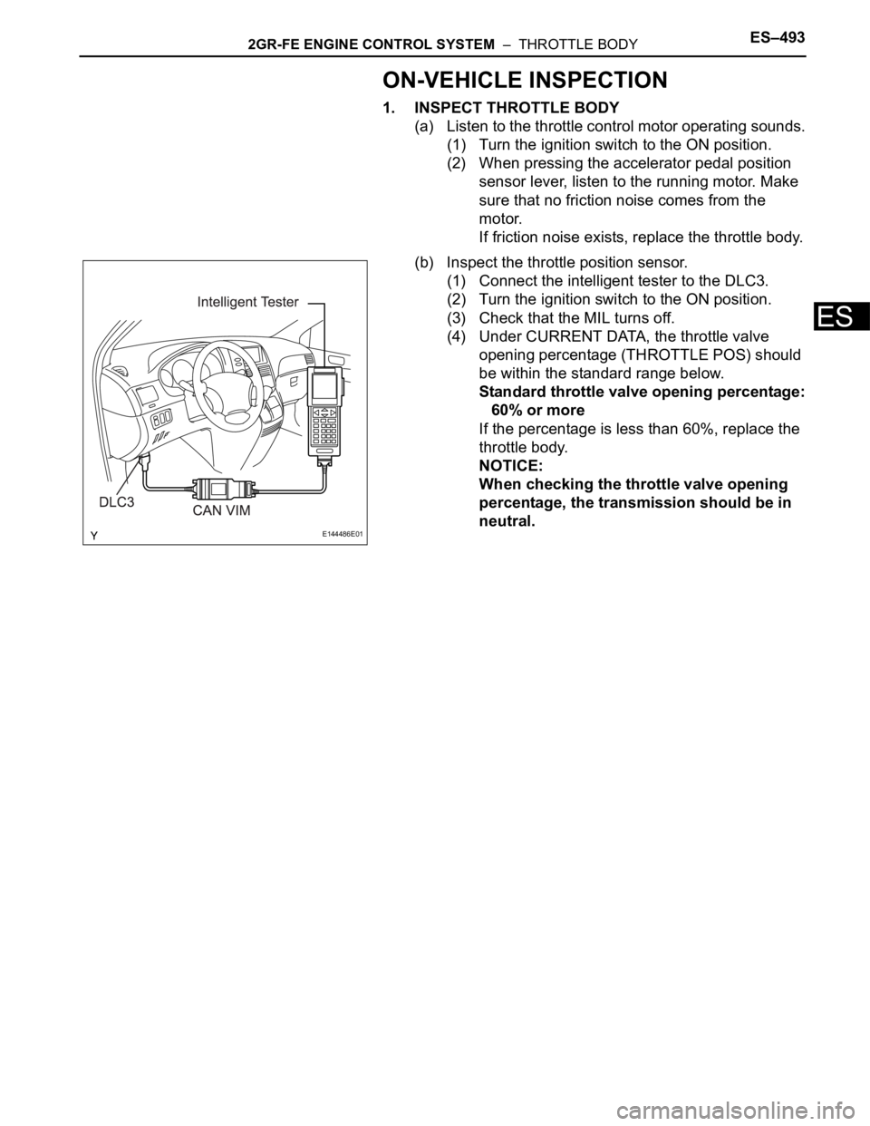
(1) Connect the intelligent tester to the DLC3.
(2) Turn the ignition switch to the ON position.
(3) Check that the MIL turns off.
(4) Under CURRENT DATA, the throttle valve
opening percentage (THROTTLE POS) should
be within the standard range below.
Standard throttle valve opening percentage:
60% or more
If the percentage is less than 60%, replace the
throttle body.
NOTICE:
When checking the throttle valve opening
percentage, the transmission should be in
neutral.
E144486E01
Page 810 of 3000

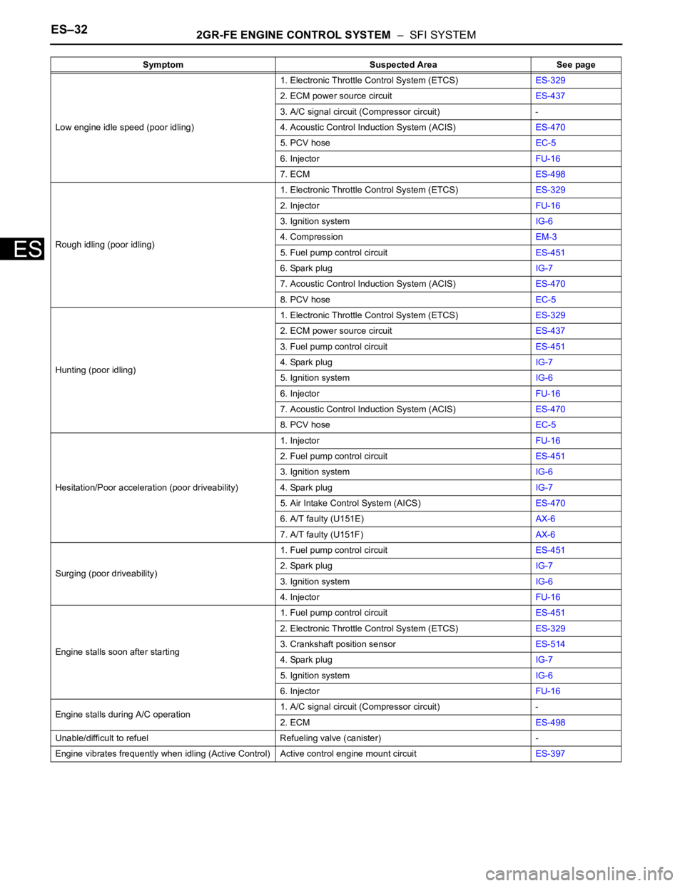
ES–322GR-FE ENGINE CONTROL SYSTEM – SFI SYSTEM
ES
Low engine idle speed (poor idling)1. Electronic Throttle Control System (ETCS)ES-329
2. ECM power source circuitES-437
3. A/C signal circuit (Compressor circuit) -
4. Acoustic Control Induction System (ACIS)ES-470
5. PCV hoseEC-5
6. InjectorFU-16
7. ECMES-498
Rough idling (poor idling)1. Electronic Throttle Control System (ETCS)ES-329
2. InjectorFU-16
3. Ignition systemIG-6
4. CompressionEM-3
5. Fuel pump control circuitES-451
6. Spark plugIG-7
7. Acoustic Control Induction System (ACIS)ES-470
8. PCV hoseEC-5
Hunting (poor idling)1. Electronic Throttle Control System (ETCS)ES-329
2. ECM power source circuitES-437
3. Fuel pump control circuitES-451
4. Spark plugIG-7
5. Ignition systemIG-6
6. InjectorFU-16
7. Acoustic Control Induction System (ACIS)ES-470
8. PCV hoseEC-5
Hesitation/Poor acceleration (poor driveability)1. InjectorFU-16
2. Fuel pump control circuitES-451
3. Ignition systemIG-6
4. Spark plugIG-7
5. Air Intake Control System (AICS)ES-470
6. A/T faulty (U151E)AX-6
7. A/T faulty (U151F)AX-6
Surging (poor driveability)1. Fuel pump control circuitES-451
2. Spark plugIG-7
3. Ignition systemIG-6
4. InjectorFU-16
Engine stalls soon after starting1. Fuel pump control circuitES-451
2. Electronic Throttle Control System (ETCS)ES-329
3. Crankshaft position sensorES-514
4. Spark plugIG-7
5. Ignition systemIG-6
6. InjectorFU-16
Engine stalls during A/C operation1. A/C signal circuit (Compressor circuit) -
2. ECMES-498
Unable/difficult to refuel Refueling valve (canister) -
Engine vibrates frequently when idling (Active Control) Active control engine mount circuitES-397 Symptom Suspected Area See page
Page 813 of 3000

2GR-FE ENGINE CONTROL SYSTEM – SFI SYSTEMES–33
ES
TERMINALS OF ECM
1. SFI SYSTEM
HINT:
The standard normal voltage between each pair of the
ECM terminals is shown in the table below. The
appropriate conditions for checking each pair of the
terminals are also indicated.
The check results should be compared with the standard
normal voltage for that pair of terminals, listed in the
"Specified Condition" column.
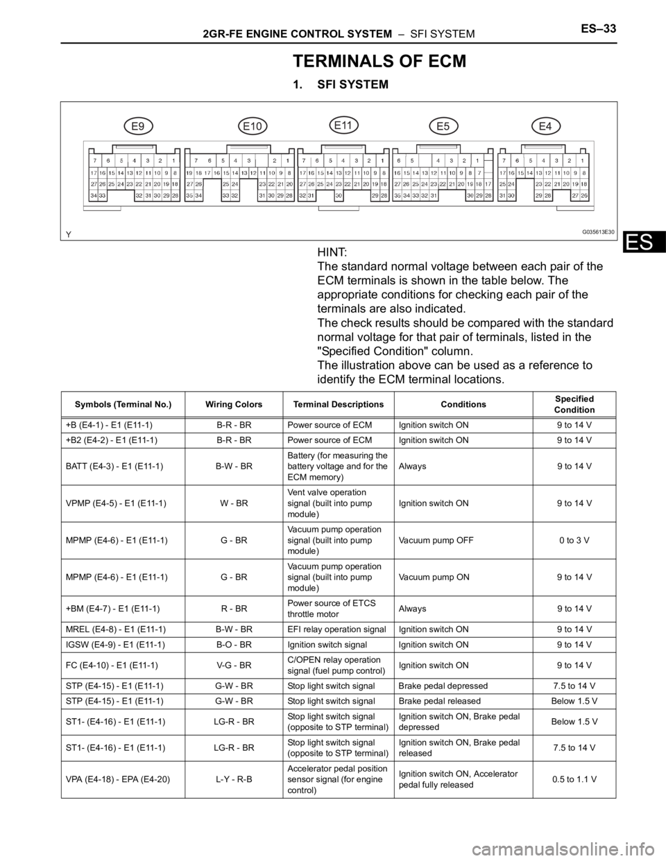
The illustration above can be used as a reference to
identify the ECM terminal locations.
G035613E30
Symbols (Terminal No.) Wiring Colors Terminal Descriptions ConditionsSpecified
Condition
+B (E4-1) - E1 (E11-1) B-R - BR Power source of ECM Ignition switch ON 9 to 14 V
+B2 (E4-2) - E1 (E11-1) B-R - BR Power source of ECM Ignition switch ON 9 to 14 V
BATT (E4-3) - E1 (E11-1) B-W - BRBattery (for measuring the
battery voltage and for the
ECM memory)Always 9 to 14 V
VPMP (E4-5) - E1 (E11-1) W - BRVent valve operation
signal (built into pump
module)Ignition switch ON 9 to 14 V
MPMP (E4-6) - E1 (E11-1) G - BRVacuum pump operation
signal (built into pump
module)Vacuum pump OFF 0 to 3 V
MPMP (E4-6) - E1 (E11-1) G - BRVacuum pump operation
signal (built into pump
module)Vacuum pump ON 9 to 14 V
+BM (E4-7) - E1 (E11-1) R - BRPower source of ETCS
throttle motorAlways 9 to 14 V
MREL (E4-8) - E1 (E11-1) B-W - BR EFI relay operation signal Ignition switch ON 9 to 14 V
IGSW (E4-9) - E1 (E11-1) B-O - BRIgnition switch signal Ignition switch ON 9 to 14 V
FC (E4-10) - E1 (E11-1) V-G - BRC/OPEN relay operation
signal (fuel pump control)Ignition switch ON 9 to 14 V
STP (E4-15) - E1 (E11-1) G-W - BR Stop light switch signal Brake pedal depressed 7.5 to 14 V
STP (E4-15) - E1 (E11-1) G-W - BR Stop light switch signal Brake pedal released Below 1.5 V
ST1- (E4-16) - E1 (E11-1) LG-R - BRStop light switch signal
(opposite to STP terminal)Ignition switch ON, Brake pedal
depressedBelow 1.5 V
ST1- (E4-16) - E1 (E11-1) LG-R - BRStop light switch signal
(opposite to STP terminal)Ignition switch ON, Brake pedal
released7.5 to 14 V
VPA (E4-18) - EPA (E4-20) L-Y - R-BAccelerator pedal position
sensor signal (for engine
control)Ignition switch ON, Accelerator
pedal fully released0.5 to 1.1 V
Page 815 of 3000

2GR-FE ENGINE CONTROL SYSTEM – SFI SYSTEMES–35
ES
STAR (NSW) (E10-8) - E1
(E11-1)B-Y - BRPark/Neutral position
switch signalIgnition switch ON, Shift lever
position P or N9 to 14 V
STAR (NSW) (E10-8) - E1
(E11-1)B-Y - BRPark/Neutral position
switch signalIgnition switch ON, Shift lever
position other than P or N9 to 14 V
STA (E11-11) - E1 (E11-1) B-L - BRStarter relay operation
signalCranking 9 to 14 V
OC2- (E11-14) - OC2+ (E11-
15)G-B - L-RCamshaft timing Oil
Control Valve (OCV)
operation signal (Intake
side)Ignition switch ONPulse generation
(see waveform 1)
OE2+ (E11-27) - OE2- (E11-
32)W - G-RCamshaft timing Oil
Control Valve (OCV)
operation signal (Intake
side)Ignition switch ONPulse generation
(see waveform 1)
OC1- (E11-16) - OC1+ (E11-
17)G-R - G-WCamshaft timing Oil
Control Valve (OCV)
operation signal (Intake
side)Ignition switch ONPulse generation
(see waveform 1)
OE1+ (E11-26) - OE1- (E11-
31)G - RCamshaft timing Oil
Control Valve (OCV)
operation signal (Intake
side)Ignition switch ONPulse generation
(see waveform 1)
VV2+ (E11-18) - VV2- (E11-
28)V - GVariable Valve Timing
(VVT) sensor signal
(Intake side)IdlingPulse generation
(see waveform 5)
VV1+ (E11-19) - VV1- (E11-
29)B-W - L-YVariable Valve Timing
(VVT) sensor signal
(Intake side)IdlingPulse generation
(see waveform 5)
NE- (E11-20) - NE+ (E11-21) B - WCrankshaft position sensor
signalIdlingPulse generation
(see waveform 5)
NE+ (E11-21) - NE- (E11-20) W - BCrankshaft position sensor
signalIdlingPulse generation
(see waveform 5)
EV2- (E11-22) - EV2+ (E11-
23)R - PVariable Valve Timing
(VVT) sensor signal
(Exhaust side)IdlingPulse generation
(see waveform 5)
EV2+ (E11-23) - EV2- (E11-
22)P - RVariable Valve Timing
(VVT) sensor signal
(Exhaust side)IdlingPulse generation
(see waveform 5)
EV1- (E11-24) - EV1+ (E11-
25)L-W - B-WVariable Valve Timing
(VVT) sensor signal
(Exhaust side)IdlingPulse generation
(see waveform 5)
EV1+ (E11-25) - EV1- (E11-
24)B-W - L-WVariable Valve Timing
(VVT) sensor signal
(Exhaust side)IdlingPulse generation
(see waveform 5)
VV2- (E11-28) - VV2+ (E11-
18)G - VVariable Valve Timing
(VVT) sensor signal
(Intake side)IdlingPulse generation
(see waveform 5)
VV1- (E11-29) - VV1+ (E11-
19)L-Y - B-WVariable Valve Timing
(VVT) sensor signal
(Intake side)IdlingPulse generation
(see waveform 5)
HT1B (E9-1) - E1 (E11-1)
HT2B (E10-5) - E1 (E11-1)L - BR
W-L - BRHeated oxygen sensor
heater operation signalIdling Below 3.0 V
HT1B (E9-1) - E1 (E11-1)
HT2B (E10-5) - E1 (E11-1)L - BR
W-L - BRHeated oxygen sensor
heater operation signalIgnition switch ON 9 to 14 V
ACM (E9-3) - E1 (E11-1) Y-G - BRVSV for active control
mount system operation
signalIgnition switch ON 9 to 14 V
M- (E9-4) - ME01 (E10-3) W - W-BThrottle drive motor
operation signal (negative
terminal)Idling with warm enginePulse generation
(see waveform 10) Symbols (Terminal No.) Wiring Colors Terminal Descriptions ConditionsSpecified
Condition
Page 816 of 3000

ES–362GR-FE ENGINE CONTROL SYSTEM – SFI SYSTEM
ES
M+ (E9-5) - ME01 (E10-3) B - W-BThrottle drive motor
operation signal (positive
terminal)Idling with warm enginePluse generation
(see waveform 9)
E02 (E9-6) - Body ground W-B - -Earth (ground) circuit of
ECMAlways Below 1 V
E01 (E9-7) - Body ground W-B - -Earth (ground) circuit of
ECMAlways Below 1 V
IGT1 (E9-8) - E1 (E11-1)
IGT2 (E9-9) - E1 (E11-1)
IGT3 (E9-10) - E1 (E11-1)
IGT4 (E9-11) - E1 (E11-1)
IGT5 (E9-12) - E1 (E11-1)
IGT6 (E9-13) - E1 (E11-1)R-L - BR
P - BR
Y- B - B R
L-Y - BR
G-Y - BR
L-R - BRIgnition coil with igniter
(ignition signal)IdlingPulse generation
(see waveform 6)
GE01 (E9-17) - E1 (E11-1) - - BRShielded earth (ground)
circuit of throttle drive
motorAlways Below 1 V
OX1B (E9-18) - E2 (E9-28)
OX2B (E10-33) - E2 (E9-28)W - BR
B - BRHeated oxygen sensor
signalWith engine speed at 2500 rpm
for 2 minutes after warming upPulse generation
(see waveform 2)
VTA2 (E9-19) - E2 (E9-28) B-R - BRThrottle position sensor
signal (for sensor
malfunction detection)Ignition switch ON, Accelerator
pedal fully released2.1 to 3.1 V
VTA2 (E9-19) - E2 (E9-28) B-R - BRThrottle position sensor
signal (for sensor
malfunction detection)Ignition switch ON, Accelerator
pedal fully depressed4.5 to 5.0 V
VTA1 (E9-20) - E2 (E9-28) LG - BRThrottle position sensor
signal (for engine control)Ignition switch ON, Throttle valve
fully closed0.5 to 1.2 V
VTA1 (E9-20) - E2 (E9-28) LG - BRThrottle position sensor
signal (for engine control)Ignition switch ON, Throttle valve
fully open3.2 to 4.8 V
THW (E9-21) - E2 (E9-28) G-B - BREngine coolant
temperature sensor signalIdling, Engine coolant
temperature 80
C (176F)0.2 to 1.0 V
THA (E9-22) - E2 (E9-28) L-B - BRIntake air temperature
sensor signalIdling, Intake air temperature
20
C (68F)0.5 to 3.4 V
VC (E9-23) - E2 (E9-28) Y - BRPower source of sensors
(specific voltage)Ignition switch ON 4.5 to 5.0 V
IGF1 (E9-24) - E1 (E11-1) W-R - BRIgnition coil with igniter
(ignition confirmation
signal)Ignition switch ON 4.5 to 5.0 V
IGF1 (E9-24) - E1 (E11-1) W-R - BRIgnition coil with igniter
(ignition confirmation
signal)IdlingPulse generation
(see waveform 6)
AICV (E9-27) - E1 (E11-1) W - BRVSV for Air intake control
system operation signalIgnition switch ON 9 to 14 V
E2 (E9-28) - E1 (E11-1) BR - BREarth (ground) circuit of
sensors for ETCSAlways Below 1 V
E2G (E9-29) - E1 (E11-1) L-W - BREarth (ground) circuit of
sensor for mass air flow
meterAlways Below 1 V
VG (E9-30) - E2G (E9-29) R - L-WMass Air Flow (MAF)
meter signalIdling, Shift lever position P or N,
A/C switch OFF0.5 to 3.0 V
ACIS (E9-33) - E1 (E11-1) R-Y - BRVSV for ACIS (Acoustic
Control Induction System)
operation signalIgnition switch ON 9 to 14 V
PRG (E9-34) - E1 (E11-1) G - BRPurge VSV for EVAP
system operation signalIgnition switch ON 9 to 14 V
PRG (E9-34) - E1 (E11-1) G - BRPurge VSV for EVAP
system operation signalIdlingPulse generation
(see waveform 7)
HA2A (E10-1) - E05 (E10-6) Y - W-BA/F sensor heater
operation signalIdling Below 3.0 V Symbols (Terminal No.) Wiring Colors Terminal Descriptions ConditionsSpecified
Condition
Page 831 of 3000

2GR-FE ENGINE CONTROL SYSTEM – SFI SYSTEMES–47
ES
KNOCK FB VAL Feedback value of knocking -
ACCEL POS #1Absolute Accelerator Pedal Position (APP)
No. 1-
ACCEL POS #2 Absolute APP No. 2 -
THROTTLE POS Throttle positionRead value with ignition switch on (Do not
start engine)
THROTTLE POS Throttle sensor positioningRead value with ignition switch on (Do not
start engine)
THROTTLE POS#2 Throttle sensor positioning #2Read value with ignition switch on (Do not
start engine)
THROTTLE MOT Throttle motor -
O2S B1 S2 Heated oxygen sensor outputPerforming INJ VOL or A/F CONTROL
function of ACTIVE TEST enables technician
to check voltage output of sensor
O2S B2 S2 Heated oxygen sensor outputPerforming INJ VOL or A/F CONTROL
function of ACTIVE TEST enables technician
to check voltage output of sensor
AFS B1 S1 A/F sensor outputPerforming INJ VOL or A/F CONTROL
function of ACTIVE TEST enables technician
to check voltage output of sensor
AFS B2 S1 A/F sensor outputPerforming INJ VOL or A/F CONTROL
function of ACTIVE TEST enables technician
to check voltage output of sensor
TOTAL FT #1 Total fuel trim of bank 1 -
TOTAL FT #2 Total fuel trim of bank 2 -
SHORT FT #1 Short-term fuel trim of bank 1Short-term fuel compensation used to
maintain air-fuel ratio at stoichiometric air-fuel
ratio
LONG FT #1 Long-term fuel trim of bank 1Overall fuel compensation carried out in long-
term to compensate for a continual deviation
of short-term fuel trim from central valve
SHORT FT #2 Short-term fuel trim of bank 2Short-term fuel compensation used to
maintain air-fuel ratio at stoichiometric air-fuel
ratio
LONG FT #2 Long-term fuel trim of bank 2Overall fuel compensation carried out in long-
term to compensate for a continual deviation
of short-term fuel trim from central valve
FUEL SYS #1 Fuel system status (bank 1)• OL (Open Loop): Has not yet satisfied
conditions to go closed loop
• CL (Closed Loop): Using heated oxygen
sensor as feedback for fuel control
• OL DRIVE: Open loop due to driving
conditions (fuel enrichment)
• OL FAULT: Open loop due to detected
system fault
• CL FAULT: Closed loop but heated
oxygen sensor, which used for fuel control
malfunctioning
FUEL SYS #2 Fuel system status (bank 2)• OL (Open Loop): Has not yet satisfied
conditions to go closed loop
• CL (Closed Loop): Using heated oxygen
sensor as feedback for fuel control
• OL DRIVE: Open loop due to driving
conditions (fuel enrichment)
• OL FAULT: Open loop due to detected
system fault
• CL FAULT: Closed loop but heated
oxygen sensor, which used for fuel control
malfunctioning
O2FT B1 S2 Fuel trim at heated oxygen sensor Same as SHORT FT #1LABEL
(Intelligent Tester Display)Measurement Item Diagnostic Note
Page 832 of 3000

ES–482GR-FE ENGINE CONTROL SYSTEM – SFI SYSTEM
ES
O2FT B2 S2 Fuel trim at heated oxygen sensor Same as SHORT FT #2
AF FT B1 S1 Fuel trim at A/F sensor -
AF FT B2 S1 Fuel trim at A/F sensor -
CAT TEMP B1 S1 Catalyst temperature -
CAT TEMP B2 S1 Catalyst temperature -
CAT TEMP B1 S2 Catalyst temperature -
CAT TEMP B2 S2 Catalyst temperature -
S O2S B1 S2 Heated oxygen sensor impedance (Sensor 2) -
S O2S B2 S2 Heated oxygen sensor impedance (Sensor 2) -
INI COOL TEMP Initial engine coolant temperature -
INI INTAKE TEMP Initial intake air temperature -
INJ VOL Injection volume -
STARTER SIG Starter signal -
PS SW Power steering signal -
PS SIGNAL Power steering signal (history)This signal status usually ON until ignition
switch turned off
CTP SW Closed throttle position switch -
A/C SIGNAL A/C signal -
ELECT LOAD SIG Electrical load signal -
STOP LIGHT SW Stop light switch -
BATTERY VOLTAGE Battery voltage -
ATM PRESSURE Atmospheric pressure -
FUEL PMP SP CTL Fuel pump speed control status -
ACIS VSVVSV for Air Intake Control Induction System
(AICS)-
VVT CTRL B2 VVT control (bank 2 Intake side) status -
EVAP (Purge) VSV EVAP purge VSV -
FUEL PUMP/SPD Fuel pump speed statusVSV for EVAP controlled by ECM (ground
side duty control)
VACUUM PUMP Key-off EVAP system pump status -
EVAP VENT VAL Key-off EVAP system vent valve status -
FAN MOTOR Electric fan motor -
TC/TE1 TC and TE1 terminals of DLC3 -
ACM ACM control status -
VVTL AIM ANGL #1 VVT aim angle -
VVT CHNG ANGL #1 VVT change angle -
VVT OCV DUTY B1 VVT OCV operation duty -
VVT EX HOLD B1VVT exhaust hold duty ratio learning value
(bank 1 Exhaust side)-
VVT EX CHG ANG1 VVT change angle (bank 1 Exhaust side) -
VVT EX OCV D B1VVT OCV (bank 1 Exhaust side) operation
duty-
VVTL AIM ANGL#2 VVT aim angle (bank 2 Intake side) -
VVT CHNG ANGL#2 VVT change angle (bank 2 Intake side) -
VVT OCV DUTY B2 VVT OCV (bank 2 Intake side) operation duty -
VVT EX HOLD B2VVT exhaust hold duty ratio learning value
(bank 2 Exhaust side)-
VVT EX CHG ANG2 VVT change angle (bank 2 Exhaust side) -
VVT EX OCV D B2VVT OCV (bank 2 Exhaust side) operation
duty- LABEL
(Intelligent Tester Display)Measurement Item Diagnostic Note
Page 934 of 3000

EM–42GR-FE ENGINE MECHANICAL – ENGINE
EM
(h) Install the 6 ignition coils.
Torque: 10 N*m (102 kgf*cm, 7 ft.*lbf)
(i) Install the intake air surge tank (See page ES-522).
10. INSPECT CO/HC
(a) Start the engine.
(b) Run the engine at 2500 rpm for approximately 180
seconds.
(c) Insert the CO/HC meter testing probe at least 40 cm
(1.3 ft.) into the tailpipe during idling.
(d) Check CO/HC concentration at idle and/or 2500
rpm.
HINT:
Check regulations and restrictions in your area
when performing 2 mode CO/HC concentration
testing (engine check at both idle speed and at 2500
rpm).
If the CO/HC concentration does not comply with
regulations, perform troubleshooting in the order
given below.
(1) Check air fuel ratio sensor and heated oxygen
sensor operation.
(2) See the table below for possible causes, and
then inspect and repair.
CO HC Problems Causes
Normal High Rough idle1. Faulty ignitions:
– Incorrect timing
– Fouled, shorted or improperly gapped plugs
2. Incorrect valve clearance
3. Leaks in intake and exhaust valves
4. Leaks in cylinders
Low HighRough idle
(fluctuating HC reading)1. Vacuum leaks:
– PCV hoses
– Intake manifold
– Throttle body
– Brake booster line
2. Lean mixture causing misfire
High HighRough idle
(black smoke from exhaust)1. Restricted air filter
2. Plugged PCV valve
3. Faulty SFI system:
– Faulty fuel pressure regulator
– Defective ECT sensor
– Defective MAF meter
–Faulty ECM
– Faulty injectors
– Faulty throttle position sensor