2007 TOYOTA SIENNA throttle position sensor
[x] Cancel search: throttle position sensorPage 1399 of 3000
AX–22U151E AUTOMATIC TRANSAXLE – AUTOMATIC TRANSAXLE SYSTEM
AX
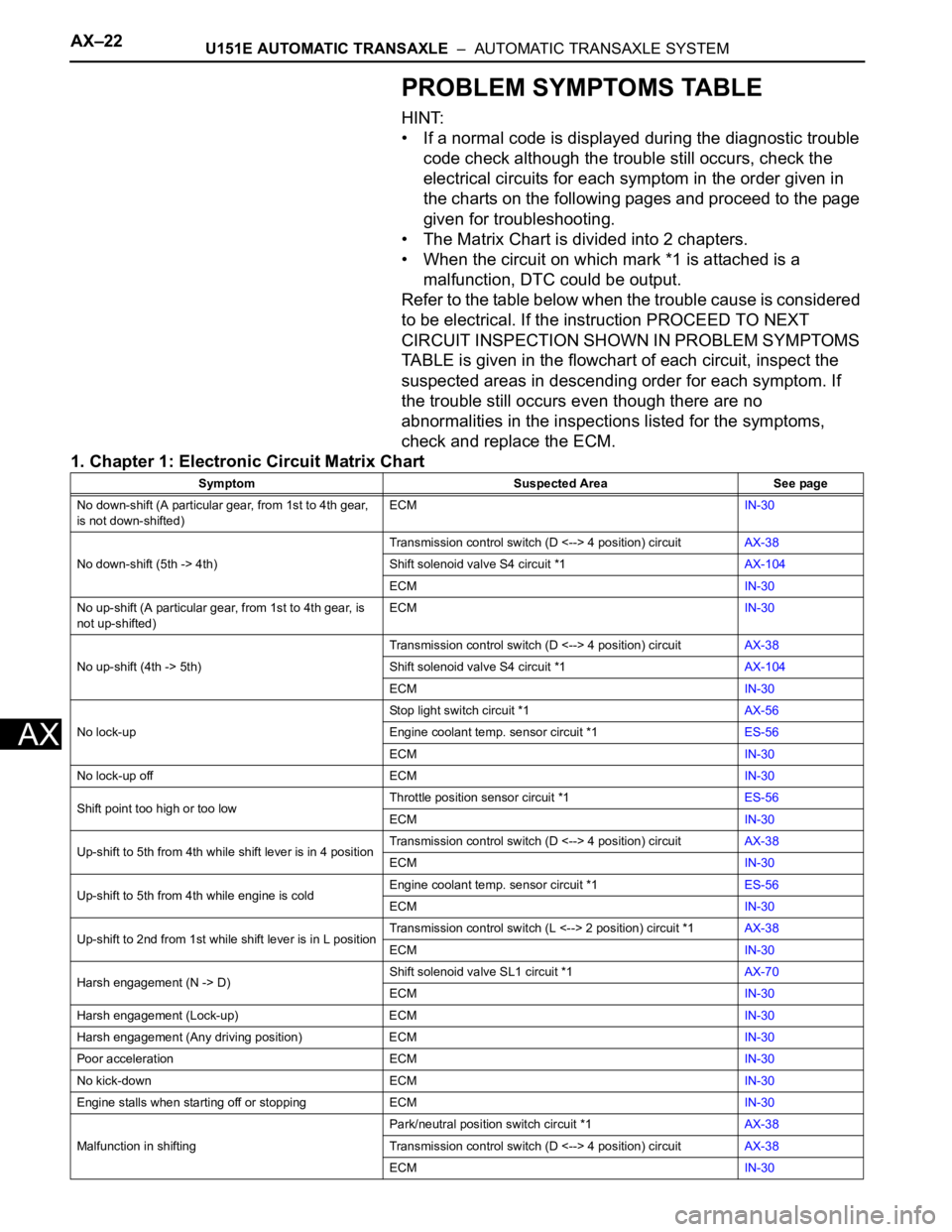
PROBLEM SYMPTOMS TABLE
HINT:
• If a normal code is displayed during the diagnostic trouble
code check although the trouble still occurs, check the
electrical circuits for each symptom in the order given in
the charts on the following pages and proceed to the page
given for troubleshooting.
• The Matrix Chart is divided into 2 chapters.
• When the circuit on which mark *1 is attached is a
malfunction, DTC could be output.
Refer to the table below when the trouble cause is considered
to be electrical. If the instruction PROCEED TO NEXT
CIRCUIT INSPECTION SHOWN IN PROBLEM SYMPTOMS
TABLE is given in the flowchart of each circuit, inspect the
suspected areas in descending order for each symptom. If
the trouble still occurs even though there are no
abnormalities in the inspections listed for the symptoms,
check and replace the ECM.
1. Chapter 1: Electronic Circuit Matrix Chart
Symptom Suspected Area See page
No down-shift (A particular gear, from 1st to 4th gear,
is not down-shifted)ECMIN-30
No down-shift (5th -> 4th)Transmission control switch (D <--> 4 position) circuitAX-38
Shift solenoid valve S4 circuit *1AX-104
ECMIN-30
No up-shift (A particular gear, from 1st to 4th gear, is
not up-shifted)ECMIN-30
No up-shift (4th -> 5th)Transmission control switch (D <--> 4 position) circuitAX-38
Shift solenoid valve S4 circuit *1AX-104
ECMIN-30
No lock-upStop light switch circuit *1AX-56
Engine coolant temp. sensor circuit *1ES-56
ECMIN-30
No lock-up off ECMIN-30
Shift point too high or too lowThrottle position sensor circuit *1ES-56
ECMIN-30
Up-shift to 5th from 4th while shift lever is in 4 positionTransmission control switch (D <--> 4 position) circuitAX-38
ECMIN-30
Up-shift to 5th from 4th while engine is coldEngine coolant temp. sensor circuit *1ES-56
ECMIN-30
Up-shift to 2nd from 1st while shift lever is in L positionTransmission control switch (L <--> 2 position) circuit *1AX-38
ECMIN-30
Harsh engagement (N -> D)Shift solenoid valve SL1 circuit *1AX-70
ECMIN-30
Harsh engagement (Lock-up) ECMIN-30
Harsh engagement (Any driving position) ECMIN-30
Poor acceleration ECMIN-30
No kick-down ECMIN-30
Engine stalls when starting off or stopping ECMIN-30
Malfunction in shiftingPark/neutral position switch circuit *1AX-38
Transmission control switch (D <--> 4 position) circuitAX-38
ECMIN-30
Page 1433 of 3000

U151E AUTOMATIC TRANSAXLE – AUTOMATIC TRANSAXLE SYSTEMAX–67
AX
SYSTEM DESCRIPTION
The ECM uses the signals from the throttle position sensor, air-flow meter, turbine (input) speed sensor,
intermediate (counter) shaft speed sensor and crankshaft position sensor to monitor the engagement
condition of the lock-up clutch.
Then the ECM compares the engagement condition of the lock-up clutch with the lock-up schedule in the
ECM memory to detect a mechanical problems of the shift solenoid valve DSL, valve body and torque
converter clutch.
MONITOR DESCRIPTION
Torque converter lock-up is controlled by the ECM based on the speed sensor (NT), speed sensor (NC),
engine rpm, engine load, engine temperature, vehicle speed, transmission temperature, and gear
selection. The ECM determines the lock-up status of the torque converter by comparing the engine rpm
(NE) to the input turbine rpm (NT). The ECM calculates the actual transmission gear by comparing input
turbine rpm (NT) to counter gear rpm (NC). When conditions are appropriate, the ECM requests "lock-up"
by applying control voltage to the shift solenoid DSL. When the DSL is turned on, it applies pressure to the
lock-up relay valve and locks the torque converter clutch.
If the ECM detects no lock-up after lock-up has been requested or if it detects lock-up when it is not
requested, the ECM interprets this as a fault in the shift solenoid valve DSL or lock-up system
performance. The ECM will turn on the MIL and store the DTC.
HINT:
Example:
When any of the following is met, the system judges it as a malfunction.
• There is a difference in rotation between the input side (engine speed) and output side (input turbine
speed) of the torque converter when the ECM commands lock-up.
(Engine speed is at least 100 rpm greater than input turbine speed.)
• There is no difference in rotation between the input side (engine speed) and output side (input turbine
speed) of the torque converter when the ECM commands lock-up off.
(The difference between engine speed and input turbine speed is less than 35 rpm.)
MONITOR STRATEGY
DTC P0741Torque Converter Clutch Solenoid Performance
(Shift Solenoid Valve DSL)
DTC No. DTC Detection Condition Trouble Area
P0741Lock-up does not occur when driving in the lock-up
range (normal driving at 80 km/h [50 mph]), or lock up
remains ON in the lock-up OFF range.
(2-trip detection logic)• Shift solenoid valve DSL remains open or closed
• Valve body is blocked
• Torque converter clutch
• Automatic transaxle (clutch, brake or gear etc.)
• Line pressure is too low
Related DTCsP0741:
Shift solenoid valve DSL/OFF malfunction
Shift solenoid valve DSL/ON malfunction
Required sensors/ComponentsShift solenoid valve DSL, Speed sensor (NT), Speed sensor (NC),
Crankshaft position sensor (NE), Throttle position sensor (VPA1),
Mass air flow sensor (MAF), Transmission temperature sensor
(THO1), Engine coolant temperature sensor (ECT)
Frequency of operation Continuous
DurationOFF malfunction (A)
Continuous.
OFF malfunction (B)
1 sec.
OFF malfunction (C)
3.5 sec.
ON malfunction
1.8 sec.
Page 1483 of 3000
U151E AUTOMATIC TRANSAXLE – AUTOMATIC TRANSAXLE SYSTEMAX–117
AX
SYSTEM DESCRIPTION
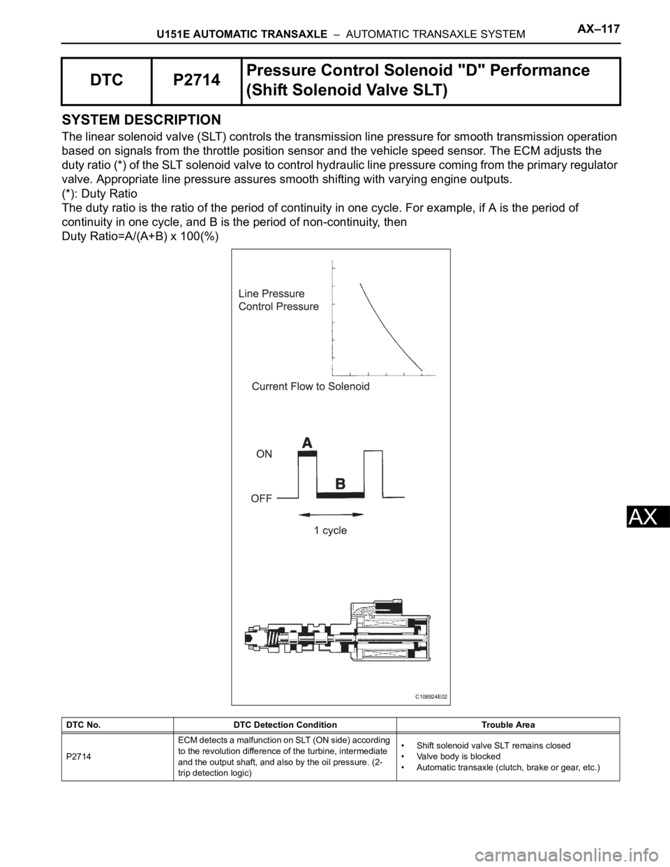
The linear solenoid valve (SLT) controls the transmission line pressure for smooth transmission operation
based on signals from the throttle position sensor and the vehicle speed sensor. The ECM adjusts the
duty ratio (*) of the SLT solenoid valve to control hydraulic line pressure coming from the primary regulator
valve. Appropriate line pressure assures smooth shifting with varying engine outputs.
(*): Duty Ratio
The duty ratio is the ratio of the period of continuity in one cycle. For example, if A is the period of
continuity in one cycle, and B is the period of non-continuity, then
Duty Ratio=A/(A+B) x 100(%)
DTC P2714Pressure Control Solenoid "D" Performance
(Shift Solenoid Valve SLT)
DTC No. DTC Detection Condition Trouble Area
P2714ECM detects a malfunction on SLT (ON side) according
to the revolution difference of the turbine, intermediate
and the output shaft, and also by the oil pressure. (2-
trip detection logic)• Shift solenoid valve SLT remains closed
• Valve body is blocked
• Automatic transaxle (clutch, brake or gear, etc.)
C108924E02
Page 1484 of 3000

AX–118U151E AUTOMATIC TRANSAXLE – AUTOMATIC TRANSAXLE SYSTEM
AX
MONITOR DESCRIPTION
In any forward position, when the difference between the revolutions of the turbine, Intermediate and
output shaft exceeds the specified value (varies with Intermediate, output speed) determined by the ECM,
the ECM illuminates the MIL and store the DTC.
When shift solenoid valve SLT remains on, the oil pressure goes down and the clutch engagement force
decreases.
NOTICE:
If you continue driving under these conditions, the clutch will burn out and the vehicle will no
longer be drivable.
MONITOR STRATEGY
TYPICAL ENABLING CONDITIONS
ON malfunction:
ON malfunction (A):
Related DTCs P2714: Shift solenoid valve SLT/ON malfunction
Required sensors/ComponentsShift solenoid valve SLT, Speed sensor (NT), Speed sensor (NC),
Crankshaft position sensor (NE)
Frequency of operation Continuous
Duration 0.5 sec.
MIL operation 2 driving cycles
Sequence of operation None
The monitor will run whenever this DTC is not present. None
Transmission range"D"
TFT (Transmission fluid temperature) -20
C (-4F) or more
TFT sensor circuitNot circuit malfunction
Turbine speed sensor circuit Not circuit malfunction
Intermediate shaft speed sensor circuit Not circuit malfunction
Output speed sensor circuitNot circuit malfunction
Shift solenoid valve SL1 circuit Not circuit malfunction
Shift solenoid valve SL2 circuit Not circuit malfunction
Shift solenoid valve SL3 circuit Not circuit malfunction
Shift solenoid valve S4 circuit Not circuit malfunction
Shift solenoid valve SR circuit Not circuit malfunction
Shift solenoid valve DSL circuit Not circuit malfunction
Shift solenoid valve SLT circuit Not circuit malfunction
Electronic throttle systemNot circuit malfunction
ECM selected gear 1st
Temporary MAIN gear 1st or 2nd or 3rd or 4th
NT - NC x Temporary MAIN gear ratio
NT: Input (turbine) speed
NC: Intermediate shaft speed100 rpm or more at Intermediate shaft speed 1,000 rpm
Temporary U/D gear Low
NC - NO x Temporary U/D gear ratio
NO: Output speed300 rpm or more at Output speed 1,000 rpm
TT
TT: Turbine Torque900 Nm or more
NT 250 rpm or more
NC 250 rpm or more
NO 250 rpm or more
Page 1489 of 3000
U151E AUTOMATIC TRANSAXLE – AUTOMATIC TRANSAXLE SYSTEMAX–123
AX
DESCRIPTION
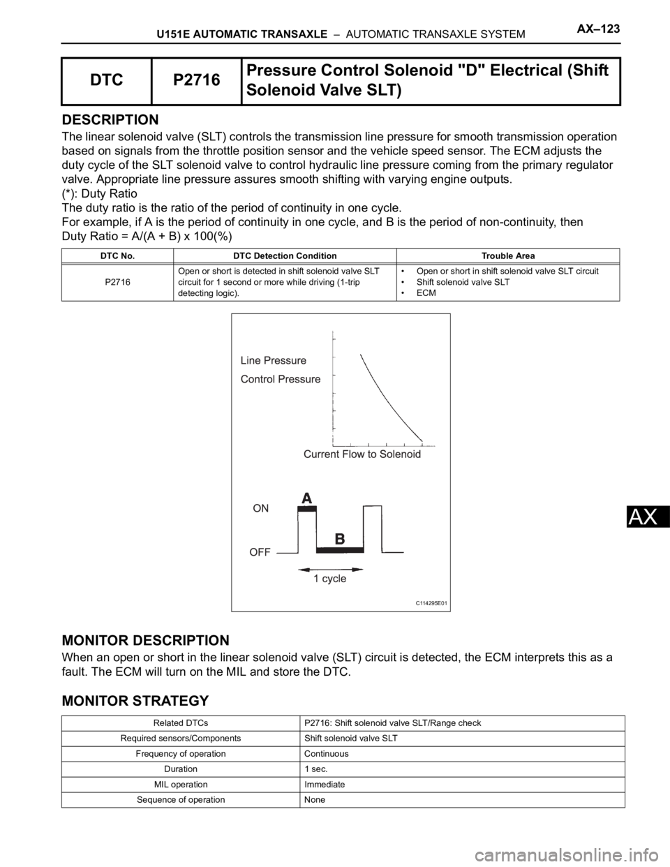
The linear solenoid valve (SLT) controls the transmission line pressure for smooth transmission operation
based on signals from the throttle position sensor and the vehicle speed sensor. The ECM adjusts the
duty cycle of the SLT solenoid valve to control hydraulic line pressure coming from the primary regulator
valve. Appropriate line pressure assures smooth shifting with varying engine outputs.
(*): Duty Ratio
The duty ratio is the ratio of the period of continuity in one cycle.
For example, if A is the period of continuity in one cycle, and B is the period of non-continuity, then
Duty Ratio = A/(A + B) x 100(%)
MONITOR DESCRIPTION
When an open or short in the linear solenoid valve (SLT) circuit is detected, the ECM interprets this as a
fault. The ECM will turn on the MIL and store the DTC.
MONITOR STRATEGY
DTC P2716Pressure Control Solenoid "D" Electrical (Shift
Solenoid Valve SLT)
DTC No. DTC Detection Condition Trouble Area
P2716Open or short is detected in shift solenoid valve SLT
circuit for 1 second or more while driving (1-trip
detecting logic).• Open or short in shift solenoid valve SLT circuit
• Shift solenoid valve SLT
•ECM
Related DTCs P2716: Shift solenoid valve SLT/Range check
Required sensors/Components Shift solenoid valve SLT
Frequency of operation Continuous
Duration 1 sec.
MIL operation Immediate
Sequence of operation None
C114295E01
Page 1525 of 3000
AX–22U151E AUTOMATIC TRANSAXLE – AUTOMATIC TRANSAXLE SYSTEM
AX
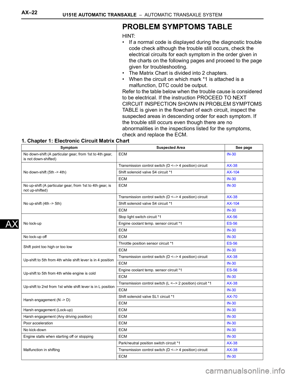
PROBLEM SYMPTOMS TABLE
HINT:
• If a normal code is displayed during the diagnostic trouble
code check although the trouble still occurs, check the
electrical circuits for each symptom in the order given in
the charts on the following pages and proceed to the page
given for troubleshooting.
• The Matrix Chart is divided into 2 chapters.
• When the circuit on which mark *1 is attached is a
malfunction, DTC could be output.
Refer to the table below when the trouble cause is considered
to be electrical. If the instruction PROCEED TO NEXT
CIRCUIT INSPECTION SHOWN IN PROBLEM SYMPTOMS
TABLE is given in the flowchart of each circuit, inspect the
suspected areas in descending order for each symptom. If
the trouble still occurs even though there are no
abnormalities in the inspections listed for the symptoms,
check and replace the ECM.
1. Chapter 1: Electronic Circuit Matrix Chart
Symptom Suspected Area See page
No down-shift (A particular gear, from 1st to 4th gear,
is not down-shifted)ECMIN-30
No down-shift (5th -> 4th)Transmission control switch (D <--> 4 position) circuitAX-38
Shift solenoid valve S4 circuit *1AX-104
ECMIN-30
No up-shift (A particular gear, from 1st to 4th gear, is
not up-shifted)ECMIN-30
No up-shift (4th -> 5th)Transmission control switch (D <--> 4 position) circuitAX-38
Shift solenoid valve S4 circuit *1AX-104
ECMIN-30
No lock-upStop light switch circuit *1AX-56
Engine coolant temp. sensor circuit *1ES-56
ECMIN-30
No lock-up off ECMIN-30
Shift point too high or too lowThrottle position sensor circuit *1ES-56
ECMIN-30
Up-shift to 5th from 4th while shift lever is in 4 positionTransmission control switch (D <--> 4 position) circuitAX-38
ECMIN-30
Up-shift to 5th from 4th while engine is coldEngine coolant temp. sensor circuit *1ES-56
ECMIN-30
Up-shift to 2nd from 1st while shift lever is in L positionTransmission control switch (L <--> 2 position) circuit *1AX-38
ECMIN-30
Harsh engagement (N -> D)Shift solenoid valve SL1 circuit *1AX-70
ECMIN-30
Harsh engagement (Lock-up) ECMIN-30
Harsh engagement (Any driving position) ECMIN-30
Poor acceleration ECMIN-30
No kick-down ECMIN-30
Engine stalls when starting off or stopping ECMIN-30
Malfunction in shiftingPark/neutral position switch circuit *1AX-38
Transmission control switch (D <--> 4 position) circuitAX-38
ECMIN-30
Page 1705 of 3000
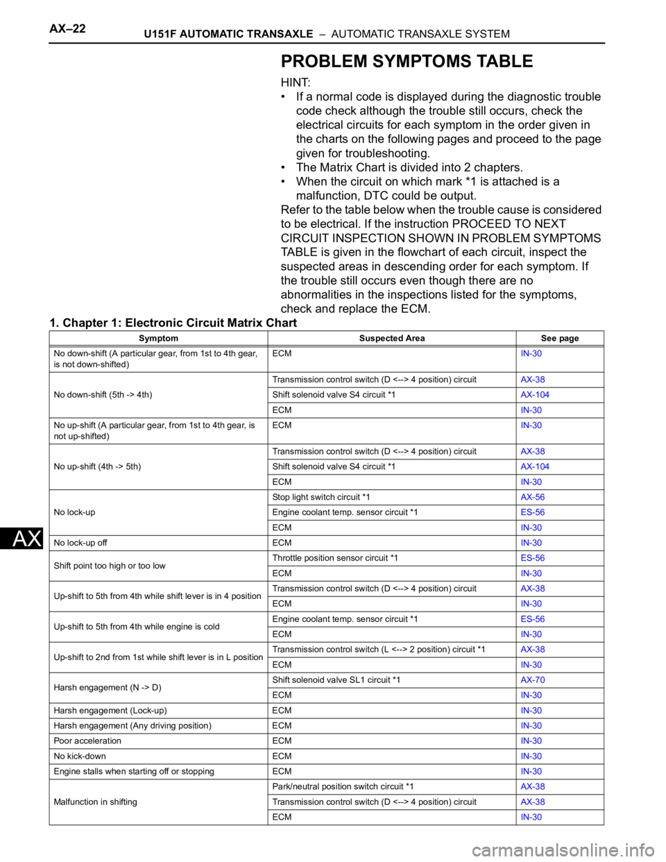
AX–22U151F AUTOMATIC TRANSAXLE – AUTOMATIC TRANSAXLE SYSTEM
AX
PROBLEM SYMPTOMS TABLE
HINT:
• If a normal code is displayed during the diagnostic trouble
code check although the trouble still occurs, check the
electrical circuits for each symptom in the order given in
the charts on the following pages and proceed to the page
given for troubleshooting.
• The Matrix Chart is divided into 2 chapters.
• When the circuit on which mark *1 is attached is a
malfunction, DTC could be output.
Refer to the table below when the trouble cause is considered
to be electrical. If the instruction PROCEED TO NEXT
CIRCUIT INSPECTION SHOWN IN PROBLEM SYMPTOMS
TABLE is given in the flowchart of each circuit, inspect the
suspected areas in descending order for each symptom. If
the trouble still occurs even though there are no
abnormalities in the inspections listed for the symptoms,
check and replace the ECM.
1. Chapter 1: Electronic Circuit Matrix Chart
Symptom Suspected Area See page
No down-shift (A particular gear, from 1st to 4th gear,
is not down-shifted)ECMIN-30
No down-shift (5th -> 4th)Transmission control switch (D <--> 4 position) circuitAX-38
Shift solenoid valve S4 circuit *1AX-104
ECMIN-30
No up-shift (A particular gear, from 1st to 4th gear, is
not up-shifted)ECMIN-30
No up-shift (4th -> 5th)Transmission control switch (D <--> 4 position) circuitAX-38
Shift solenoid valve S4 circuit *1AX-104
ECMIN-30
No lock-upStop light switch circuit *1AX-56
Engine coolant temp. sensor circuit *1ES-56
ECMIN-30
No lock-up off ECMIN-30
Shift point too high or too lowThrottle position sensor circuit *1ES-56
ECMIN-30
Up-shift to 5th from 4th while shift lever is in 4 positionTransmission control switch (D <--> 4 position) circuitAX-38
ECMIN-30
Up-shift to 5th from 4th while engine is coldEngine coolant temp. sensor circuit *1ES-56
ECMIN-30
Up-shift to 2nd from 1st while shift lever is in L positionTransmission control switch (L <--> 2 position) circuit *1AX-38
ECMIN-30
Harsh engagement (N -> D)Shift solenoid valve SL1 circuit *1AX-70
ECMIN-30
Harsh engagement (Lock-up) ECMIN-30
Harsh engagement (Any driving position) ECMIN-30
Poor acceleration ECMIN-30
No kick-down ECMIN-30
Engine stalls when starting off or stopping ECMIN-30
Malfunction in shiftingPark/neutral position switch circuit *1AX-38
Transmission control switch (D <--> 4 position) circuitAX-38
ECMIN-30
Page 1739 of 3000

U151F AUTOMATIC TRANSAXLE – AUTOMATIC TRANSAXLE SYSTEMAX–67
AX
SYSTEM DESCRIPTION
The ECM uses the signals from the throttle position sensor, air-flow meter, turbine (input) speed sensor,
intermediate (counter) shaft speed sensor and crankshaft position sensor to monitor the engagement
condition of the lock-up clutch.
Then the ECM compares the engagement condition of the lock-up clutch with the lock-up schedule in the
ECM memory to detect a mechanical problems of the shift solenoid valve DSL, valve body and torque
converter clutch.
MONITOR DESCRIPTION
Torque converter lock-up is controlled by the ECM based on the speed sensor (NT), speed sensor (NC),
engine rpm, engine load, engine temperature, vehicle speed, transmission temperature, and gear
selection. The ECM determines the lock-up status of the torque converter by comparing the engine rpm
(NE) to the input turbine rpm (NT). The ECM calculates the actual transmission gear by comparing input
turbine rpm (NT) to counter gear rpm (NC). When conditions are appropriate, the ECM requests "lock-up"
by applying control voltage to the shift solenoid DSL. When the DSL is turned on, it applies pressure to the
lock-up relay valve and locks the torque converter clutch.
If the ECM detects no lock-up after lock-up has been requested or if it detects lock-up when it is not
requested, the ECM interprets this as a fault in the shift solenoid valve DSL or lock-up system
performance. The ECM will turn on the MIL and store the DTC.
HINT:
Example:
When any of the following is met, the system judges it as a malfunction.
• There is a difference in rotation between the input side (engine speed) and output side (input turbine
speed) of the torque converter when the ECM commands lock-up.
(Engine speed is at least 100 rpm greater than input turbine speed.)
• There is no difference in rotation between the input side (engine speed) and output side (input turbine
speed) of the torque converter when the ECM commands lock-up off.
(The difference between engine speed and input turbine speed is less than 35 rpm.)
MONITOR STRATEGY
DTC P0741Torque Converter Clutch Solenoid Performance
(Shift Solenoid Valve DSL)
DTC No. DTC Detection Condition Trouble Area
P0741Lock-up does not occur when driving in the lock-up
range (normal driving at 80 km/h [50 mph]), or lock up
remains ON in the lock-up OFF range.
(2-trip detection logic)• Shift solenoid valve DSL remains open or closed
• Valve body is blocked
• Torque converter clutch
• Automatic transaxle (clutch, brake or gear etc.)
• Line pressure is too low
Related DTCsP0741:
Shift solenoid valve DSL/OFF malfunction
Shift solenoid valve DSL/ON malfunction
Required sensors/ComponentsShift solenoid valve DSL, Speed sensor (NT), Speed sensor (NC),
Crankshaft position sensor (NE), Throttle position sensor (VPA1),
Mass air flow sensor (MAF), Transmission temperature sensor
(THO1), Engine coolant temperature sensor (ECT)
Frequency of operation Continuous
DurationOFF malfunction (A)
Continuous.
OFF malfunction (B)
1 sec.
OFF malfunction (C)
3.5 sec.
ON malfunction
1.8 sec.