2007 TOYOTA SIENNA throttle position sensor
[x] Cancel search: throttle position sensorPage 383 of 3000
2GR-FE ENGINE CONTROL SYSTEM – SFI SYSTEMES–77
ES
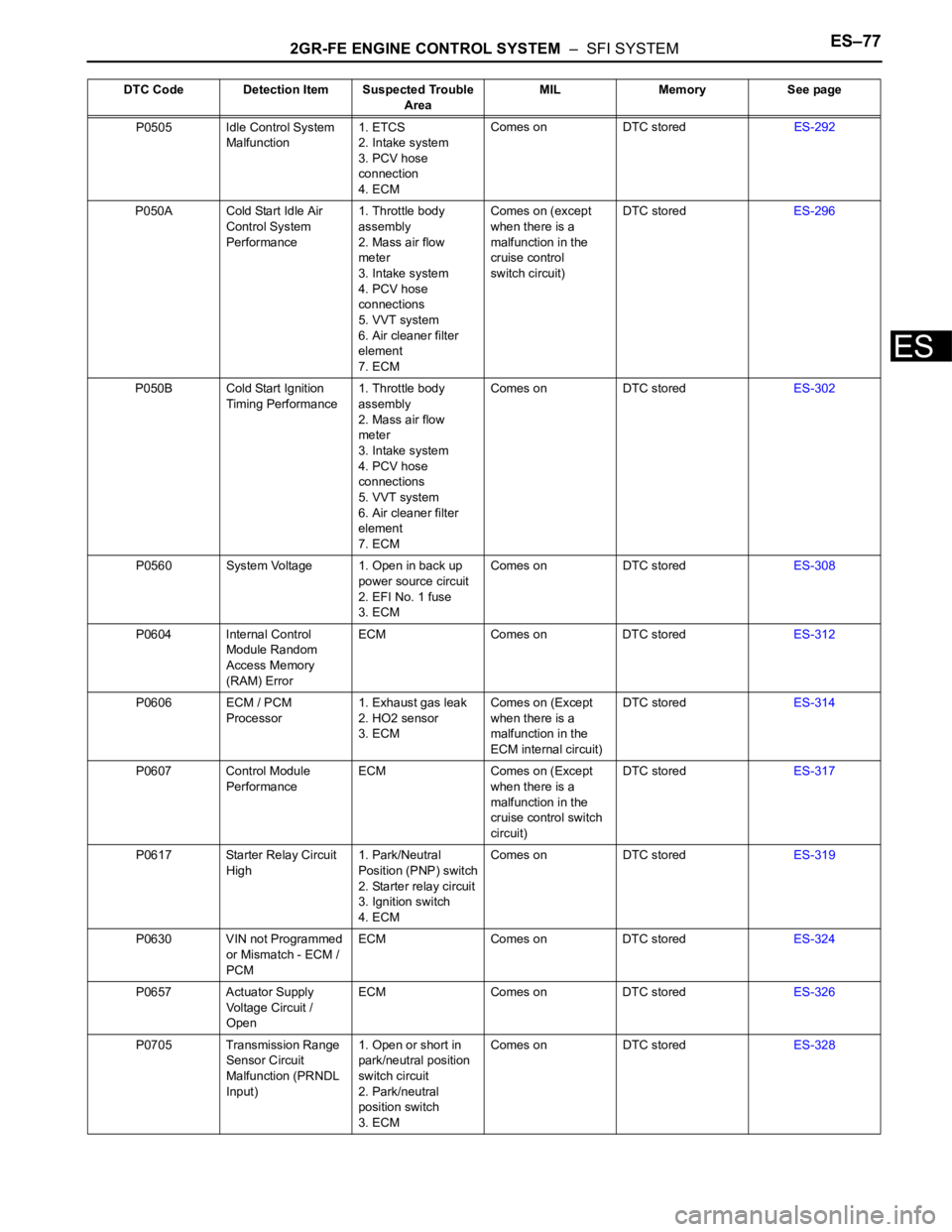
P0505 Idle Control System
Malfunction1. ETCS
2. Intake system
3. PCV hose
connection
4. ECMComes on DTC storedES-292
P050A Cold Start Idle Air
Control System
Performance1. Throttle body
assembly
2. Mass air flow
meter
3. Intake system
4. PCV hose
connections
5. VVT system
6. Air cleaner filter
element
7. ECMComes on (except
when there is a
malfunction in the
cruise control
switch circuit)DTC storedES-296
P050B Cold Start Ignition
Timing Performance1. Throttle body
assembly
2. Mass air flow
meter
3. Intake system
4. PCV hose
connections
5. VVT system
6. Air cleaner filter
element
7. ECMComes on DTC storedES-302
P0560 System Voltage 1. Open in back up
power source circuit
2. EFI No. 1 fuse
3. ECMComes on DTC storedES-308
P0604 Internal Control
Module Random
Access Memory
(RAM) ErrorECM Comes on DTC storedES-312
P0606 ECM / PCM
Processor1. Exhaust gas leak
2. HO2 sensor
3. ECMComes on (Except
when there is a
malfunction in the
ECM internal circuit)DTC storedES-314
P0607 Control Module
PerformanceECM Comes on (Except
when there is a
malfunction in the
cruise control switch
circuit)DTC storedES-317
P0617 Starter Relay Circuit
High1. Park/Neutral
Position (PNP) switch
2. Starter relay circuit
3. Ignition switch
4. ECMComes on DTC storedES-319
P0630 VIN not Programmed
or Mismatch - ECM /
PCMECM Comes on DTC storedES-324
P0657 Actuator Supply
Voltage Circuit /
OpenECM Comes on DTC storedES-326
P0705 Transmission Range
Sensor Circuit
Malfunction (PRNDL
Input)1. Open or short in
park/neutral position
switch circuit
2. Park/neutral
position switch
3. ECMComes on DTC storedES-328 DTC Code Detection Item Suspected Trouble
AreaMIL Memory See page
Page 384 of 3000
ES–782GR-FE ENGINE CONTROL SYSTEM – SFI SYSTEM
ES
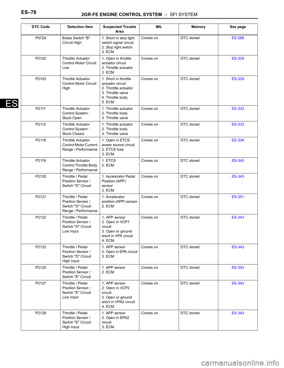
P0724 Brake Switch "B"
Circuit High1. Short in stop light
switch signal circuit
2. Stop light switch
3. ECMComes on DTC storedES-288
P2102 Throttle Actuator
Control Motor Circuit
Low1. Open in throttle
actuator circuit
2. Throttle actuator
3. ECMComes on DTC storedES-329
P2103 Throttle Actuator
Control Motor Circuit
High1. Short in throttle
actuator circuit
2. Throttle actuator
3. Throttle valve
4. Throttle body
5. ECMComes on DTC storedES-329
P2111 Throttle Actuator
Control System -
Stuck Open1. Throttle actuator
2. Throttle body
3. Throttle valveComes on DTC storedES-333
P2112 Throttle Actuator
Control System -
Stuck Closed1. Throttle actuator
2. Throttle body
3. Throttle valveComes on DTC storedES-333
P2118 Throttle Actuator
Control Motor Current
Range / Performance1. Open in ETCS
power source circuit
2. ETCS fuse
3. ECMComes on DTC storedES-336
P2119 Throttle Actuator
Control Throttle Body
Range / Performance1. ETCS
2. ECMComes on DTC storedES-340
P2120 Throttle / Pedal
Position Sensor /
Switch "D" Circuit1. Accelerator Pedal
Position (APP)
sensor
2. ECMComes on DTC storedES-343
P2121 Throttle / Pedal
Position Sensor /
Switch "D" Circuit
Range / Performance1. Accelerator
position (APP) sensor
2. ECMComes on DTC storedES-351
P2122 Throttle / Pedal
Position Sensor /
Switch "D" Circuit
Low Input1. APP sensor
2. Open in VCP1
circuit
3. Open or ground
short in VPA circuit
4. ECMComes on DTC storedES-343
P2123 Throttle / Pedal
Position Sensor /
Switch "D" Circuit
High Input1. APP sensor
2. Open in EPA circuit
3. ECMComes on DTC storedES-343
P2125 Throttle / Pedal
Position Sensor /
Switch "E" Circuit1. APP sensor
2. ECMComes on DTC storedES-343
P2127 Throttle / Pedal
Position Sensor /
Switch "E" Circuit
Low Input1. APP sensor
2. Open in VCP2
circuit
3. Open or ground
short in VPA2 circuit
4. ECMComes on DTC storedES-343
P2128 Throttle / Pedal
Position Sensor /
Switch "E" Circuit
High Input1. APP sensor
2. Open in EPA2
circuit
3. ECMComes on DTC storedES-343 DTC Code Detection Item Suspected Trouble
AreaMIL Memory See page
Page 385 of 3000

2GR-FE ENGINE CONTROL SYSTEM – SFI SYSTEMES–79
ES
P2135 Throttle / Pedal
Position Sensor /
Switch "A" / "B"
Voltage Correlation1. Short between
VTA1 and VTA2
circuits
2. TP sensor (built
into throttle body)
3. ECMComes on DTC storedES-145
P2138 Throttle / Pedal
Position Sensor /
Switch "D" / "E"
Voltage Correlation1. Short between
VPA and VPA2
circuits
2. APP sensor
3. ECMComes on DTC storedES-343
P2195 Oxygen (A/F) Sensor
Signal Stuck Lean
(Bank 1 Sensor 1)1. Open or short in A/
F sensor (bank 1, 2
sensor 1) circuit
2. A/F sensor (bank
1, 2 sensor 1)
3. A/F sensor (bank
1, 2 sensor 1) heater
4. A/F sensor heater
relay
5. A/F sensor heater
and relay circuits
6. Intake system
7. Fuel pressure
8. Injector
9. ECMComes on DTC storedES-355
P2196 Oxygen (A/F) Sensor
Signal Stuck Rich
(Bank 1 Sensor 1)1. Open or short in A/
F sensor (bank 1, 2
sensor 1) circuit
2. A/F sensor (bank
1, 2 sensor 1)
3. A/F sensor (bank
1, 2 sensor 1) heater
4. A/F sensor heater
relay
5. A/F sensor heater
and relay circuits
6. Intake system
7. Fuel pressure
8. Injector
9. ECMComes on DTC storedES-355
P2197 Oxygen (A/F) Sensor
Signal Stuck Lean
(Bank 2 Sensor 1)1. Open or short in A/
F sensor (bank 1, 2
sensor 1) circuit
2. A/F sensor (bank
1, 2 sensor 1)
3. A/F sensor (bank
1, 2 sensor 1) heater
4. A/F sensor heater
relay
5. A/F sensor heater
and relay circuits
6. Intake system
7. Fuel pressure
8. Injector
9. ECMComes on DTC storedES-355 DTC Code Detection Item Suspected Trouble
AreaMIL Memory See page
Page 389 of 3000
2GR-FE ENGINE CONTROL SYSTEM – SFI SYSTEMES–83
ES
DESCRIPTION
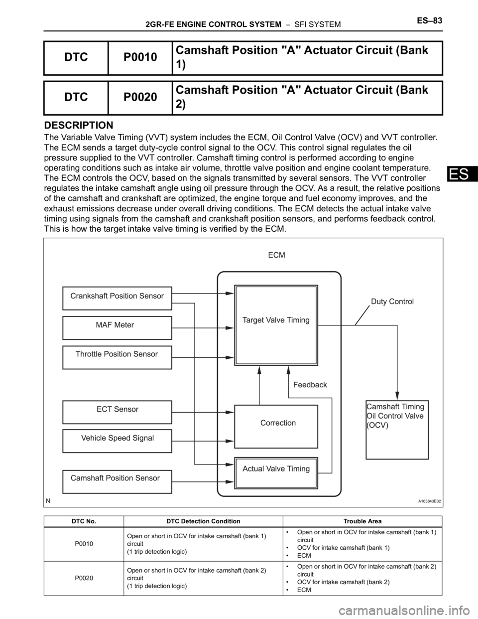
The Variable Valve Timing (VVT) system includes the ECM, Oil Control Valve (OCV) and VVT controller.
The ECM sends a target duty-cycle control signal to the OCV. This control signal regulates the oil
pressure supplied to the VVT controller. Camshaft timing control is performed according to engine
operating conditions such as intake air volume, throttle valve position and engine coolant temperature.
The ECM controls the OCV, based on the signals transmitted by several sensors. The VVT controller
regulates the intake camshaft angle using oil pressure through the OCV. As a result, the relative positions
of the camshaft and crankshaft are optimized, the engine torque and fuel economy improves, and the
exhaust emissions decrease under overall driving conditions. The ECM detects the actual intake valve
timing using signals from the camshaft and crankshaft position sensors, and performs feedback control.
This is how the target intake valve timing is verified by the ECM.
DTC P0010Camshaft Position "A" Actuator Circuit (Bank
1)
DTC P0020Camshaft Position "A" Actuator Circuit (Bank
2)
DTC No. DTC Detection Condition Trouble Area
P0010Open or short in OCV for intake camshaft (bank 1)
circuit
(1 trip detection logic)• Open or short in OCV for intake camshaft (bank 1)
circuit
• OCV for intake camshaft (bank 1)
•ECM
P0020Open or short in OCV for intake camshaft (bank 2)
circuit
(1 trip detection logic)• Open or short in OCV for intake camshaft (bank 2)
circuit
• OCV for intake camshaft (bank 2)
•ECM
A103843E02
Page 401 of 3000
2GR-FE ENGINE CONTROL SYSTEM – SFI SYSTEMES–95
ES
DESCRIPTION
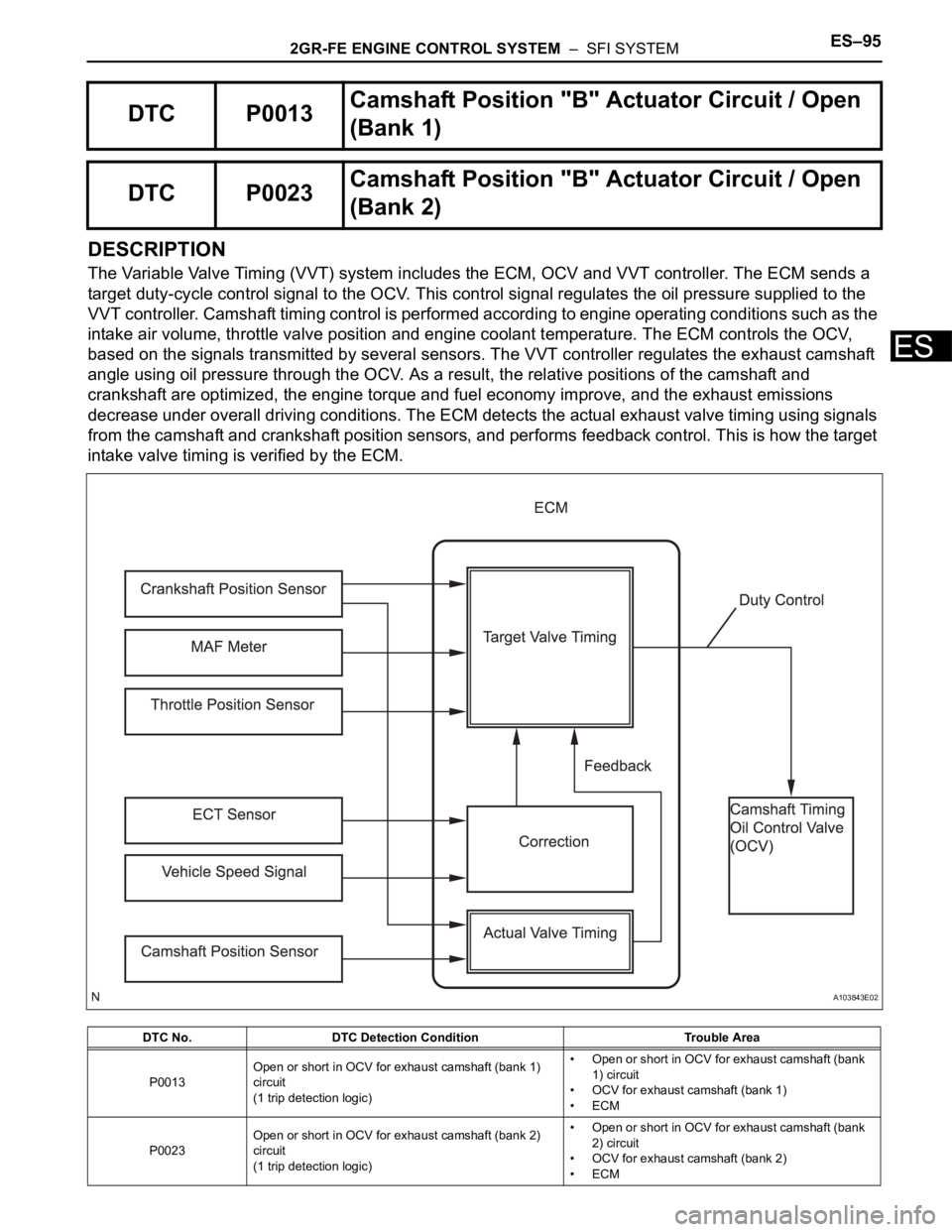
The Variable Valve Timing (VVT) system includes the ECM, OCV and VVT controller. The ECM sends a
target duty-cycle control signal to the OCV. This control signal regulates the oil pressure supplied to the
VVT controller. Camshaft timing control is performed according to engine operating conditions such as the
intake air volume, throttle valve position and engine coolant temperature. The ECM controls the OCV,
based on the signals transmitted by several sensors. The VVT controller regulates the exhaust camshaft
angle using oil pressure through the OCV. As a result, the relative positions of the camshaft and
crankshaft are optimized, the engine torque and fuel economy improve, and the exhaust emissions
decrease under overall driving conditions. The ECM detects the actual exhaust valve timing using signals
from the camshaft and crankshaft position sensors, and performs feedback control. This is how the target
intake valve timing is verified by the ECM.
DTC P0013Camshaft Position "B" Actuator Circuit / Open
(Bank 1)
DTC P0023Camshaft Position "B" Actuator Circuit / Open
(Bank 2)
DTC No. DTC Detection Condition Trouble Area
P0013Open or short in OCV for exhaust camshaft (bank 1)
circuit
(1 trip detection logic)• Open or short in OCV for exhaust camshaft (bank
1) circuit
• OCV for exhaust camshaft (bank 1)
•ECM
P0023Open or short in OCV for exhaust camshaft (bank 2)
circuit
(1 trip detection logic)• Open or short in OCV for exhaust camshaft (bank
2) circuit
• OCV for exhaust camshaft (bank 2)
•ECM
A103843E02
Page 430 of 3000
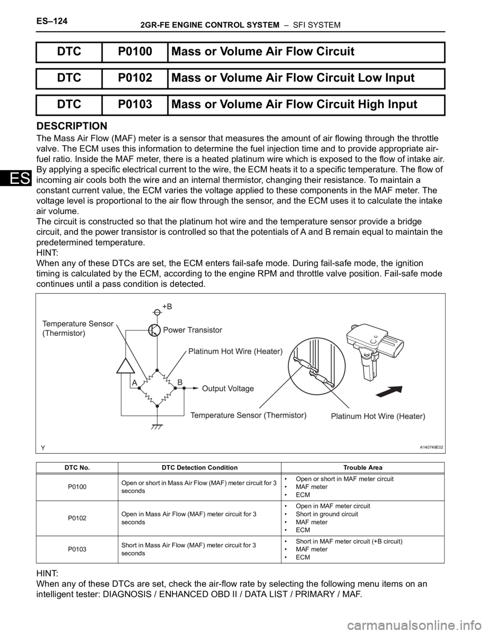
ES–1242GR-FE ENGINE CONTROL SYSTEM – SFI SYSTEM
ES
DESCRIPTION
The Mass Air Flow (MAF) meter is a sensor that measures the amount of air flowing through the throttle
valve. The ECM uses this information to determine the fuel injection time and to provide appropriate air-
fuel ratio. Inside the MAF meter, there is a heated platinum wire which is exposed to the flow of intake air.
By applying a specific electrical current to the wire, the ECM heats it to a specific temperature. The flow of
incoming air cools both the wire and an internal thermistor, changing their resistance. To maintain a
constant current value, the ECM varies the voltage applied to these components in the MAF meter. The
voltage level is proportional to the air flow through the sensor, and the ECM uses it to calculate the intake
air volume.
The circuit is constructed so that the platinum hot wire and the temperature sensor provide a bridge
circuit, and the power transistor is controlled so that the potentials of A and B remain equal to maintain the
predetermined temperature.
HINT:
When any of these DTCs are set, the ECM enters fail-safe mode. During fail-safe mode, the ignition
timing is calculated by the ECM, according to the engine RPM and throttle valve position. Fail-safe mode
continues until a pass condition is detected.
HINT:
When any of these DTCs are set, check the air-flow rate by selecting the following menu items on an
intelligent tester: DIAGNOSIS / ENHANCED OBD II / DATA LIST / PRIMARY / MAF.
DTC P0100 Mass or Volume Air Flow Circuit
DTC P0102 Mass or Volume Air Flow Circuit Low Input
DTC P0103 Mass or Volume Air Flow Circuit High Input
DTC No. DTC Detection Condition Trouble Area
P0100Open or short in Mass Air Flow (MAF) meter circuit for 3
seconds• Open or short in MAF meter circuit
• MAF meter
•ECM
P0102Open in Mass Air Flow (MAF) meter circuit for 3
seconds• Open in MAF meter circuit
• Short in ground circuit
• MAF meter
•ECM
P0103Short in Mass Air Flow (MAF) meter circuit for 3
seconds• Short in MAF meter circuit (+B circuit)
• MAF meter
•ECM
A140749E02
Page 436 of 3000

ES–1302GR-FE ENGINE CONTROL SYSTEM – SFI SYSTEM
ES
DESCRIPTION
Refer to DTC P0100 (See page ES-116).
MONITOR DESCRIPTION
The MAF meter is a sensor that measures the amount of air flowing through the throttle valve. The ECM
uses this information to determine the fuel injection time and to provide an appropriate air-fuel ratio.
Inside the MAF meter, there is a heated platinum wire which is exposed to the flow of intake air. By
applying a specific electrical current to the wire, the ECM heats it to a specific temperature. The flow of
incoming air cools both the wire and an internal thermistor, changing their resistance. To maintain a
constant current value, the ECM varies the voltage applied to these components of the MAF meter. The
voltage level is proportional to the air flow through the sensor, and the ECM uses it to calculate the intake
air volume.
If there is a defect in the sensor, or an open or short in the circuit, the voltage level deviates from the
normal operating range. The ECM interprets this deviation as a malfunction in the MAF meter and sets the
DTC.
Example:
If the voltage is more than 2.2 V, or less than 0.73 V while idling, the ECM determines that there is a
malfunction in the MAF meter and sets the DTC.
MONITOR STRATEGY
TYPICAL ENABLING CONDITIONS
DTC P0101Mass or Volume Air Flow Circuit Range / Perfor-
mance Problem
DTC No. DTC Detection Condition Trouble Area
P01011. High voltage:
Conditions (a), (b) and (c) continue for more than
10 seconds (2 trip detection logic):
(a) Engine speed is less than 2000 rpm
(b) Engine coolant temperature is 70
C (158F) or
higher
(c) Voltage output of Mass Air Flow (MAF) meter is
more than 1.24 V (varies with Throttle Position [TP]
sensor voltage)
2. Low voltage:
Conditions (a) and (b) continue for more than 10
seconds (2 trip detection logic):
(a) Engine speed is more than 300 rpm
(b) Voltage output of MAF meter is less than 0.80 V
(varies with TP sensor voltage)MAF meter
Related DTCs P0101: Mass air flow meter rationality
Required Sensors / Components (Main) Mass air flow meter
Required Sensors / Components (Related)Crankshaft position sensor, engine coolant temperature sensor and throttle position
sensor
Frequency of Operation Continuous
Duration 10 times
MIL Operation 2 driving cycles
Sequence of Operation None
The monitor will run whenever these DTCs are not
presentP0115, P0116, P0117, P0118 (ECT Sensor), P0120, P0121, P0122, P0123, P0220,
P0222, P0223, P2135 (TP Sensor), P0125 (Insufficient ECT for Closed Loop),
P0335 (CKP Sensor), P0340 (CMP Sensor)
Throttle position (TP sensor voltage) 0.24 V or more
Page 459 of 3000

2GR-FE ENGINE CONTROL SYSTEM – SFI SYSTEMES–153
ES
HINT:
These DTCs relate to the Throttle Position (TP) sensor.
DESCRIPTION
HINT:
This ETC (Electrical Throttle Control System) does not use a throttle cable.
The Throttle Position (TP) sensor is mounted on the throttle body, and detects the opening angle of the
throttle valve. This sensor is a non-contact type, and uses Hall-effect elements, in order to yield accurate
signals, even in extreme driving conditions, such as at high speeds as well as very low speeds.
The TP sensor has two sensor circuits which each transmits a signal, VTA1 and VTA2. VTA1 is used to
detect the throttle valve angle and VTA2 is used to detect malfunctions in VTA1. The sensor signal
voltages vary between 0 V and 5 V in proportion to the throttle valve opening angle, and are transmitted to
the VTA terminals of the ECM.
As the valve closes, the sensor output voltage decreases and as the valve opens, the sensor output
voltage increases. The ECM calculates the throttle valve opening angle according to these signals and
controls the throttle actuator in response to driver inputs. These signals are also used in calculations such
as air-fuel ratio correction, power increase correction and fuel-cut control.
DTC P0120Throttle / Pedal Position Sensor / Switch "A"
Circuit
DTC P0122Throttle / Pedal Position Sensor / Switch "A"
Circuit Low Input
DTC P0123Throttle / Pedal Position Sensor / Switch "A"
Circuit High Input
DTC P0220Throttle / Pedal Position Sensor / Switch "B"
Circuit
DTC P0222Throttle / Pedal Position Sensor / Switch "B"
Circuit Low Input
DTC P0223Throttle / Pedal Position Sensor / Switch "B"
Circuit High Input
DTC P2135Throttle / Pedal Position Sensor / Switch "A" /
"B" Voltage Correlation