Page 1326 of 3000
ST–122GR-FE STARTING – STARTER
ST
6. INSTALL STARTER YOKE ASSEMBLY
(a) Align the key of the starter yoke with the keyway of
repair service starter kit.
(b) Install the starter yoke with the 2 through bolts.
Torque: 6.0 N*m (61 kgf*cm, 53 in.*lbf)
7. INSTALL REPAIR SERVICE STARTER KIT
(a) Apply grease to the plunger and the hook.
(b) Hang the plunger hook of the repair service starter
kit to the drive lever.
(c) Install the plunger and return spring.
(d) Install the repair service starter kit with the 2 screws.
Torque: 7.5 N*m (76 kgf*cm, 66 in.*lbf)
(e) Connect the lead wire to the repair service starter kit
with the nut.
Torque: 10 N*m (102 kgf*cm, 7 ft.*lbf)
A079728E01
A079720
A079729
A079719
A079718
Page 1334 of 3000

2GR-FE STARTING – STARTERST–11
ST
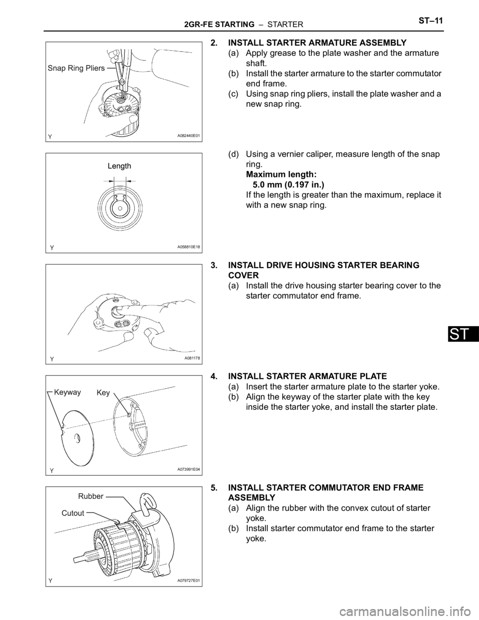
2. INSTALL STARTER ARMATURE ASSEMBLY
(a) Apply grease to the plate washer and the armature
shaft.
(b) Install the starter armature to the starter commutator
end frame.
(c) Using snap ring pliers, install the plate washer and a
new snap ring.
(d) Using a vernier caliper, measure length of the snap
ring.
Maximum length:
5.0 mm (0.197 in.)
If the length is greater than the maximum, replace it
with a new snap ring.
3. INSTALL DRIVE HOUSING STARTER BEARING
COVER
(a) Install the drive housing starter bearing cover to the
starter commutator end frame.
4. INSTALL STARTER ARMATURE PLATE
(a) Insert the starter armature plate to the starter yoke.
(b) Align the keyway of the starter plate with the key
inside the starter yoke, and install the starter plate.
5. INSTALL STARTER COMMUTATOR END FRAME
ASSEMBLY
(a) Align the rubber with the convex cutout of starter
yoke.
(b) Install starter commutator end frame to the starter
yoke.
A082440E01
A058810E18
A081178
A073991E04
A079727E01
Page 1335 of 3000
ST–122GR-FE STARTING – STARTER
ST
6. INSTALL STARTER YOKE ASSEMBLY
(a) Align the key of the starter yoke with the keyway of
repair service starter kit.
(b) Install the starter yoke with the 2 through bolts.
Torque: 6.0 N*m (61 kgf*cm, 53 in.*lbf)
7. INSTALL REPAIR SERVICE STARTER KIT
(a) Apply grease to the plunger and the hook.
(b) Hang the plunger hook of the repair service starter
kit to the drive lever.
(c) Install the plunger and return spring.
(d) Install the repair service starter kit with the 2 screws.
Torque: 7.5 N*m (76 kgf*cm, 66 in.*lbf)
(e) Connect the lead wire to the repair service starter kit
with the nut.
Torque: 10 N*m (102 kgf*cm, 7 ft.*lbf)
A079728E01
A079720
A079729
A079719
A079718
Page 1339 of 3000

ST–162GR-FE STARTING – IGNITION SWITCH
ST
REMOVAL
1. DISCONNECT CABLE FROM NEGATIVE BATTERY
TERMINAL
2. REMOVE STEERING COLUMN COVER LOWER
(a) Insert the key into the ignition key cylinder and
release the steering lock.
(b) Turn the steering wheel clockwise to gain access to
the screw and remove the screw.
(c) Turn the steering wheel counterclockwise to gain
access to the screw and remove the screw.
(d) Detach the 4 claws, and remove the steering
column cover lower.
3. REMOVE IGNITION SWITCH ASSEMBLY
(a) Disconnect the ignition switch connector.
(b) Remove the 2 screws and ignition switch.
INSPECTION
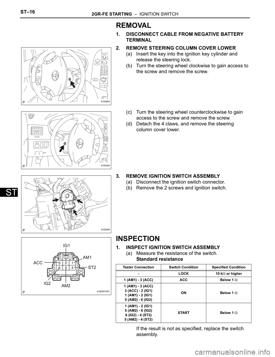
1. INSPECT IGNITION SWITCH ASSEMBLY
(a) Measure the resistance of the switch.
Standard resistance
If the result is not as specified, replace the switch
assembly.
A160244
A160245
A160246
A160247E01
Tester Connection Switch Condition Specified Condition
-LOCK10 k
or higher
1 (AM1) - 3 (ACC) ACC Below 1
1 (AM1) - 3 (ACC)
3 (ACC) - 2 (IG1)
1 (AM1) - 2 (IG1)
5 (AM2) - 6 (IG2)ON Below 1
1 (AM1) - 2 (IG1)
5 (AM2) - 6 (IG2)
6 (IG2) - 4 (ST2)
5 (AM2) - 4 (ST2)START Below 1
Page 1340 of 3000
2GR-FE STARTING – IGNITION SWITCHST–17
ST
INSTALLATION
1. INSTALL IGNITION SWITCH ASSEMBLY
(a) Install the ignition switch with the 2 screws.
(b) Install the ignition switch connector.
2. INSTALL STEERING COLUMN COVER LOWER
(a) Attach the 4 claws to install the steering column
cover lower.
(b) Insert the key into the ignition key cylinder and
release the steering lock.
(c) Turn the steering wheel counterclockwise and install
the screw.
(d) Turn the steering wheel clockwise and install the
screw.
3. CONNECT CABLE TO NEGATIVE BATTERY
TERMINAL
A160246
A160245
A160244
Page 1528 of 3000

AX–142U151E AUTOMATIC TRANSAXLE – SHIFT LOCK SYSTEM
AX
SHIFT LOCK SYSTEM
ON-VEHICLE INSPECTION
1. CHECK SHIFT LOCK OPERATION
(a) Move the shift lever to the P position.
(b) Turn the ignition switch to the LOCK position.
(c) Check that the shift lever cannot be moved to any
position other than P.
(d) Turn the ignition switch to the on position, depress
the brake pedal and check that the shift lever can be
moved to another position. If operation can not be
done as specified, inspect the shift lock control unit.
2. CHECK SHIFT LOCK RELEASE BUTTON
OPERATION
(a) Using a small screwdriver, remove the shift lock
release cover.
(b) When operating the shift lever with the shift lock
release button pressed, check that the lever can be
moved to any position other than P.
If operation can not be done as specified, check the
shift lever assembly installation condition.
3. CHECK KEY INTERLOCK OPERATION
(a) Turn the ignition switch to the ON position.
(b) Depress the brake pedal and move the shift lever to
any position other than P.
(c) Check that the ignition key cannot be turned to the
LOCK position.
(d) Move the shift lever to the P position, turn the
ignition key to the LOCK position and check that the
ignition key can be removed.
If operation cannot be done as specified, inspect the
shift lock control unit.
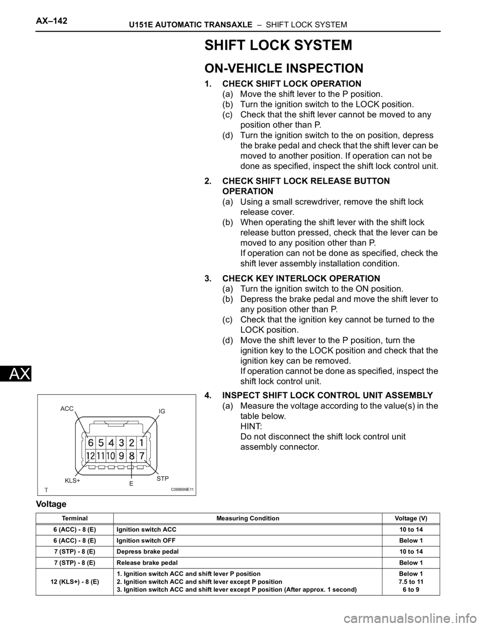
4. INSPECT SHIFT LOCK CONTROL UNIT ASSEMBLY
(a) Measure the voltage according to the value(s) in the
table below.
HINT:
Do not disconnect the shift lock control unit
assembly connector.
Voltage
C098999E11
Terminal Measuring Condition Voltage (V)
6 (ACC) - 8 (E) Ignition switch ACC10 to 14
6 (ACC) - 8 (E) Ignition switch OFFBelow 1
7 (STP) - 8 (E) Depress brake pedal10 to 14
7 (STP) - 8 (E) Release brake pedalBelow 1
12 (KLS+) - 8 (E)1. Ignition switch ACC and shift lever P position
2. Ignition switch ACC and shift lever except P position
3. Ignition switch ACC and shift lever except P position (After approx. 1 second)Below 1
7.5 to 11
6 to 9
Page 1529 of 3000

U151E AUTOMATIC TRANSAXLE – SHIFT LOCK SYSTEMAX–143
AX
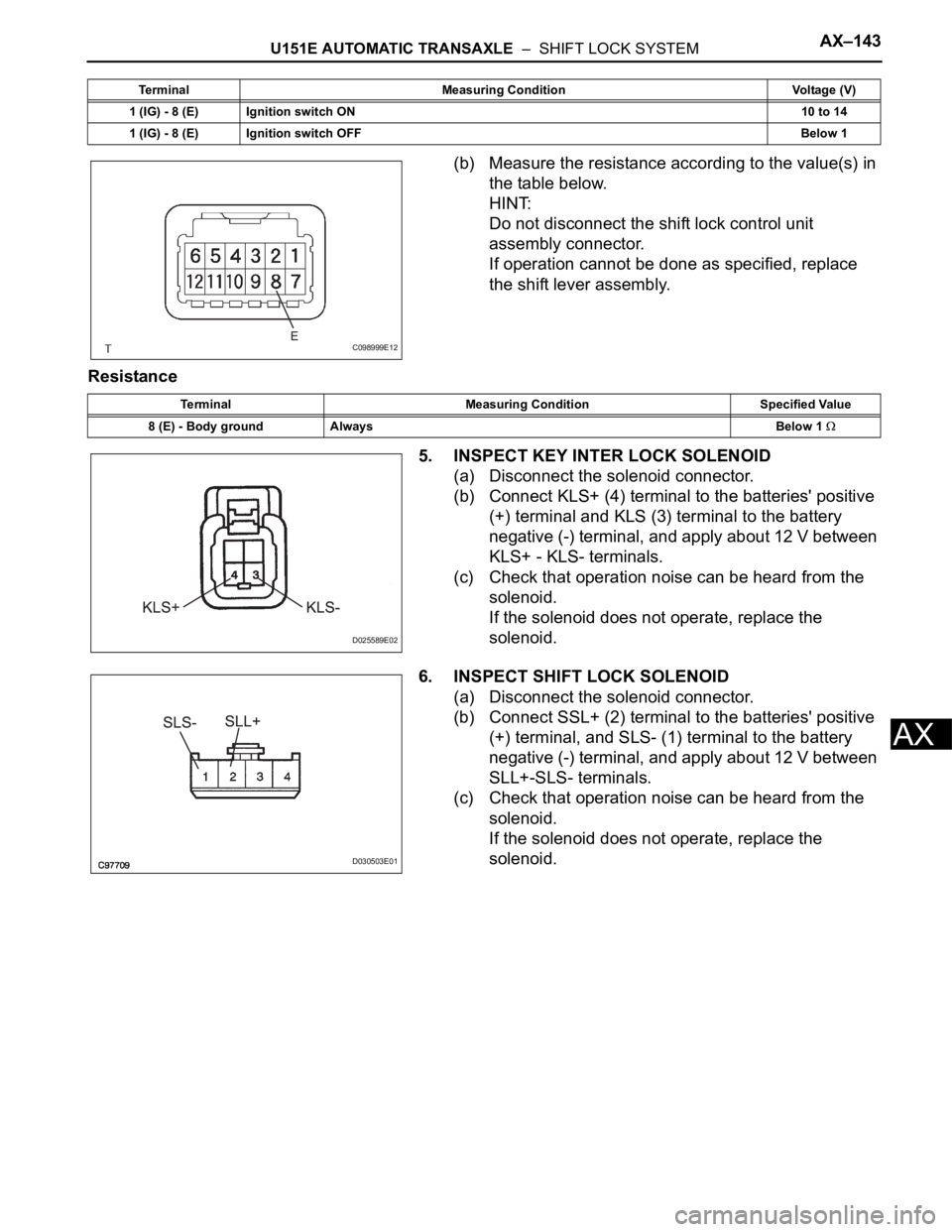
(b) Measure the resistance according to the value(s) in
the table below.
HINT:
Do not disconnect the shift lock control unit
assembly connector.
If operation cannot be done as specified, replace
the shift lever assembly.
Resistance
5. INSPECT KEY INTER LOCK SOLENOID
(a) Disconnect the solenoid connector.
(b) Connect KLS+ (4) terminal to the batteries' positive
(+) terminal and KLS (3) terminal to the battery
negative (-) terminal, and apply about 12 V between
KLS+ - KLS- terminals.
(c) Check that operation noise can be heard from the
solenoid.
If the solenoid does not operate, replace the
solenoid.
6. INSPECT SHIFT LOCK SOLENOID
(a) Disconnect the solenoid connector.
(b) Connect SSL+ (2) terminal to the batteries' positive
(+) terminal, and SLS- (1) terminal to the battery
negative (-) terminal, and apply about 12 V between
SLL+-SLS- terminals.
(c) Check that operation noise can be heard from the
solenoid.
If the solenoid does not operate, replace the
solenoid.
1 (IG) - 8 (E) Ignition switch ON10 to 14
1 (IG) - 8 (E) Ignition switch OFFBelow 1 Terminal Measuring Condition Voltage (V)
C098999E12
Terminal Measuring Condition Specified Value
8 (E) - Body ground AlwaysBelow 1
D025589E02
D030503E01
Page 1541 of 3000
U151E AUTOMATIC TRANSAXLE – SHIFT LEVERAX–153
AX
5. INSTALL POSITION INDICATOR HOUSING
ASSEMBLY
(a) install the position indicator housing assembly to the
instrument cluster finish panel assembly center.
6. INSTALL SHIFT LEVER KNOB SUB-ASSEMBLY
(a) install the shift lever knob sub-assembly.
7. ADJUST SHIFT LEVER POSITION
HINT:
(See page AX-149)
8. INSPECT SHIFT LEVER POSITION
HINT:
(See page AX-148)
9. INSPECT KEY INTER LOCK OPERATION
HINT:
(See page AX-142)
10. INSPECT SHIFT LOCK OPERATION
HINT:
(See page AX-142)
11. INSPECT SHIFT LOCK RELEASE BUTTON
OPERATION
HINT:
(See page AX-142)
C086303E02
C086302E02