2007 TOYOTA SIENNA key
[x] Cancel search: keyPage 244 of 3000

EI–4ENGINE IMMOBILISER – ENGINE IMMOBILISER SYSTEM
EI
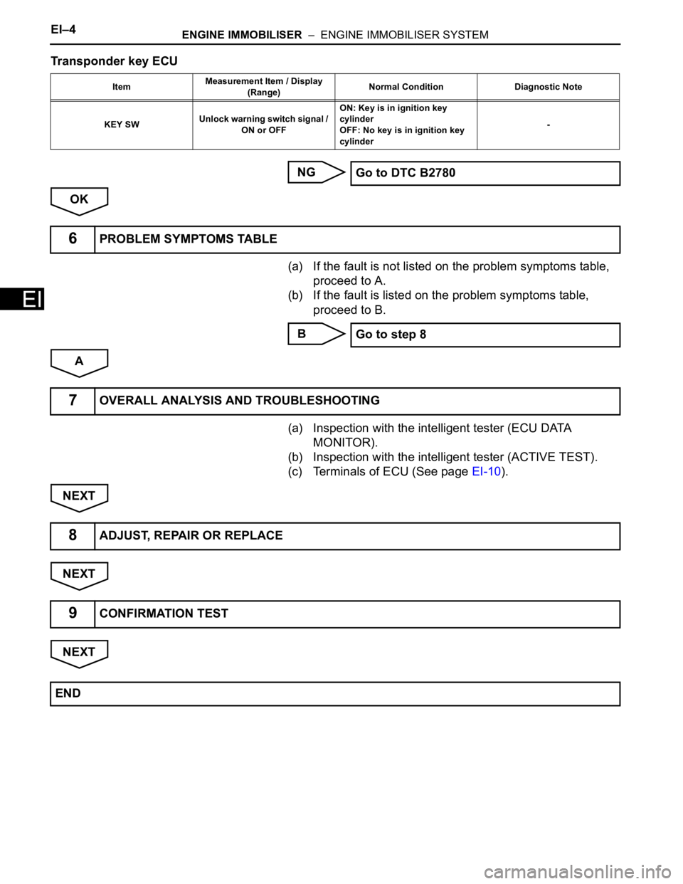
Transponder key ECU
NG
OK
(a) If the fault is not listed on the problem symptoms table,
proceed to A.
(b) If the fault is listed on the problem symptoms table,
proceed to B.
B
A
(a) Inspection with the intelligent tester (ECU DATA
MONITOR).
(b) Inspection with the intelligent tester (ACTIVE TEST).
(c) Terminals of ECU (See page EI-10).
NEXT
NEXT
NEXT
ItemMeasurement Item / Display
(Range)Normal Condition Diagnostic Note
KEY SWUnlock warning switch signal /
ON or OFFON: Key is in ignition key
cylinder
OFF: No key is in ignition key
cylinder-
Go to DTC B2780
6PROBLEM SYMPTOMS TABLE
Go to step 8
7OVERALL ANALYSIS AND TROUBLESHOOTING
8ADJUST, REPAIR OR REPLACE
9CONFIRMATION TEST
END
Page 300 of 3000

SE–8SEAT – FRONT POWER SEAT CONTROL SYSTEM
SE
Main body ECUPower seat control switch and
ECU• Driver side door courtesy light
switch signal
• Key unlock warning switch
signal
• Ignition switch signalBEAN Transmitting ECU
(Transmitter)Receiving ECU Signals Communication method
Page 353 of 3000

2GR-FE ENGINE CONTROL SYSTEM – SFI SYSTEMES–27
ES
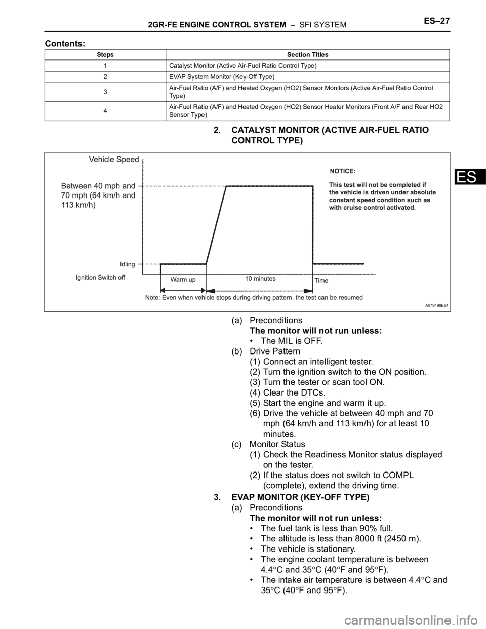
Contents:
2. CATALYST MONITOR (ACTIVE AIR-FUEL RATIO
CONTROL TYPE)
(a) Preconditions
The monitor will not run unless:
• The MIL is OFF.
(b) Drive Pattern
(1) Connect an intelligent tester.
(2) Turn the ignition switch to the ON position.
(3) Turn the tester or scan tool ON.
(4) Clear the DTCs.
(5) Start the engine and warm it up.
(6) Drive the vehicle at between 40 mph and 70
mph (64 km/h and 113 km/h) for at least 10
minutes.
(c) Monitor Status
(1) Check the Readiness Monitor status displayed
on the tester.
(2) If the status does not switch to COMPL
(complete), extend the driving time.
3. EVAP MONITOR (KEY-OFF TYPE)
(a) Preconditions
The monitor will not run unless:
• The fuel tank is less than 90% full.
• The altitude is less than 8000 ft (2450 m).
• The vehicle is stationary.
• The engine coolant temperature is between
4.4
C and 35C (40F and 95F).
• The intake air temperature is between 4.4
C and
35
C (40F and 95F).
Steps Section Titles
1 Catalyst Monitor (Active Air-Fuel Ratio Control Type)
2 EVAP System Monitor (Key-Off Type)
3Air-Fuel Ratio (A/F) and Heated Oxygen (HO2) Sensor Monitors (Active Air-Fuel Ratio Control
Ty p e )
4Air-Fuel Ratio (A/F) and Heated Oxygen (HO2) Sensor Heater Monitors (Front A/F and Rear HO2
Sensor Type)
A079199E84
Page 366 of 3000

ES–482GR-FE ENGINE CONTROL SYSTEM – SFI SYSTEM
ES
O2FT B2 S2 Fuel trim at heated oxygen sensor Same as SHORT FT #2
AF FT B1 S1 Fuel trim at A/F sensor -
AF FT B2 S1 Fuel trim at A/F sensor -
CAT TEMP B1 S1 Catalyst temperature -
CAT TEMP B2 S1 Catalyst temperature -
CAT TEMP B1 S2 Catalyst temperature -
CAT TEMP B2 S2 Catalyst temperature -
S O2S B1 S2 Heated oxygen sensor impedance (Sensor 2) -
S O2S B2 S2 Heated oxygen sensor impedance (Sensor 2) -
INI COOL TEMP Initial engine coolant temperature -
INI INTAKE TEMP Initial intake air temperature -
INJ VOL Injection volume -
STARTER SIG Starter signal -
PS SW Power steering signal -
PS SIGNAL Power steering signal (history)This signal status usually ON until ignition
switch turned off
CTP SW Closed throttle position switch -
A/C SIGNAL A/C signal -
ELECT LOAD SIG Electrical load signal -
STOP LIGHT SW Stop light switch -
BATTERY VOLTAGE Battery voltage -
ATM PRESSURE Atmospheric pressure -
FUEL PMP SP CTL Fuel pump speed control status -
ACIS VSVVSV for Air Intake Control Induction System
(AICS)-
VVT CTRL B2 VVT control (bank 2 Intake side) status -
EVAP (Purge) VSV EVAP purge VSV -
FUEL PUMP/SPD Fuel pump speed statusVSV for EVAP controlled by ECM (ground
side duty control)
VACUUM PUMP Key-off EVAP system pump status -
EVAP VENT VAL Key-off EVAP system vent valve status -
FAN MOTOR Electric fan motor -
TC/TE1 TC and TE1 terminals of DLC3 -
ACM ACM control status -
VVTL AIM ANGL #1 VVT aim angle -
VVT CHNG ANGL #1 VVT change angle -
VVT OCV DUTY B1 VVT OCV operation duty -
VVT EX HOLD B1VVT exhaust hold duty ratio learning value
(bank 1 Exhaust side)-
VVT EX CHG ANG1 VVT change angle (bank 1 Exhaust side) -
VVT EX OCV D B1VVT OCV (bank 1 Exhaust side) operation
duty-
VVTL AIM ANGL#2 VVT aim angle (bank 2 Intake side) -
VVT CHNG ANGL#2 VVT change angle (bank 2 Intake side) -
VVT OCV DUTY B2 VVT OCV (bank 2 Intake side) operation duty -
VVT EX HOLD B2VVT exhaust hold duty ratio learning value
(bank 2 Exhaust side)-
VVT EX CHG ANG2 VVT change angle (bank 2 Exhaust side) -
VVT EX OCV D B2VVT OCV (bank 2 Exhaust side) operation
duty- LABEL
(Intelligent Tester Display)Measurement Item Diagnostic Note
Page 445 of 3000

2GR-FE ENGINE CONTROL SYSTEM – SFI SYSTEMES–139
ES
TYPICAL ENABLING CONDITIONS
All:
After engine stop:
After cold engine start:
TYPICAL MALFUNCTION THRESHOLDS
After engine stop:
After cold engine start:
WIRING DIAGRAM
Refer to DTC P0110 (See page ES-126).
INSPECTION PROCEDURE
(a) Connect the intelligent tester to the DLC3.
(b) Turn the ignition switch to the ON position.
(c) Turn the tester on.
(d) Enter the following menus: DIAGNOSIS / ENHANCED
OBD II / DTC INFO / CURRENT CODES.
Required Sensors / Components (Main) Intake Air Temperature (IAT) sensor
Required Sensors / Components (Sub) -
Frequency of Operation Once per driving cycle
Duration 5 hours
MIL Operation 2 driving cycles
Sequence of Operation None
Monitor runs whenever following DTCs are not present None
Time after engine start 10 seconds or more
Battery voltage 10.5 V or more
ECT sensor OK
ECT change since engine stopped Less than 180
C (356F)
ECT before engine stop 70
C (158F) or more
Time that MAF is low before engine stop 70 minutes
Accumulated MAF amount before engine stop 3774 g or more
Key-off duration 30 minutes
Key-off duration 5 hours
Time after engine start 10 seconds or more
ECT sensor OK
ECT 70
C (158F) or more
Accumulated MAF amount 3774 g or more
One of the following conditions 1 or 2 is met: -
1. Duration while engine load is low 120 seconds or more
2. Duration while engine load is high 10 seconds or more
IAT change Less than 1
C (2F)
IAT change Less than 1
C (2F)
1CHECK ANY OTHER DTCS OUTPUT (IN ADDITION TO DTC P0111)
Page 558 of 3000

2GR-FE ENGINE CONTROL SYSTEM – SFI SYSTEMES–265
ES
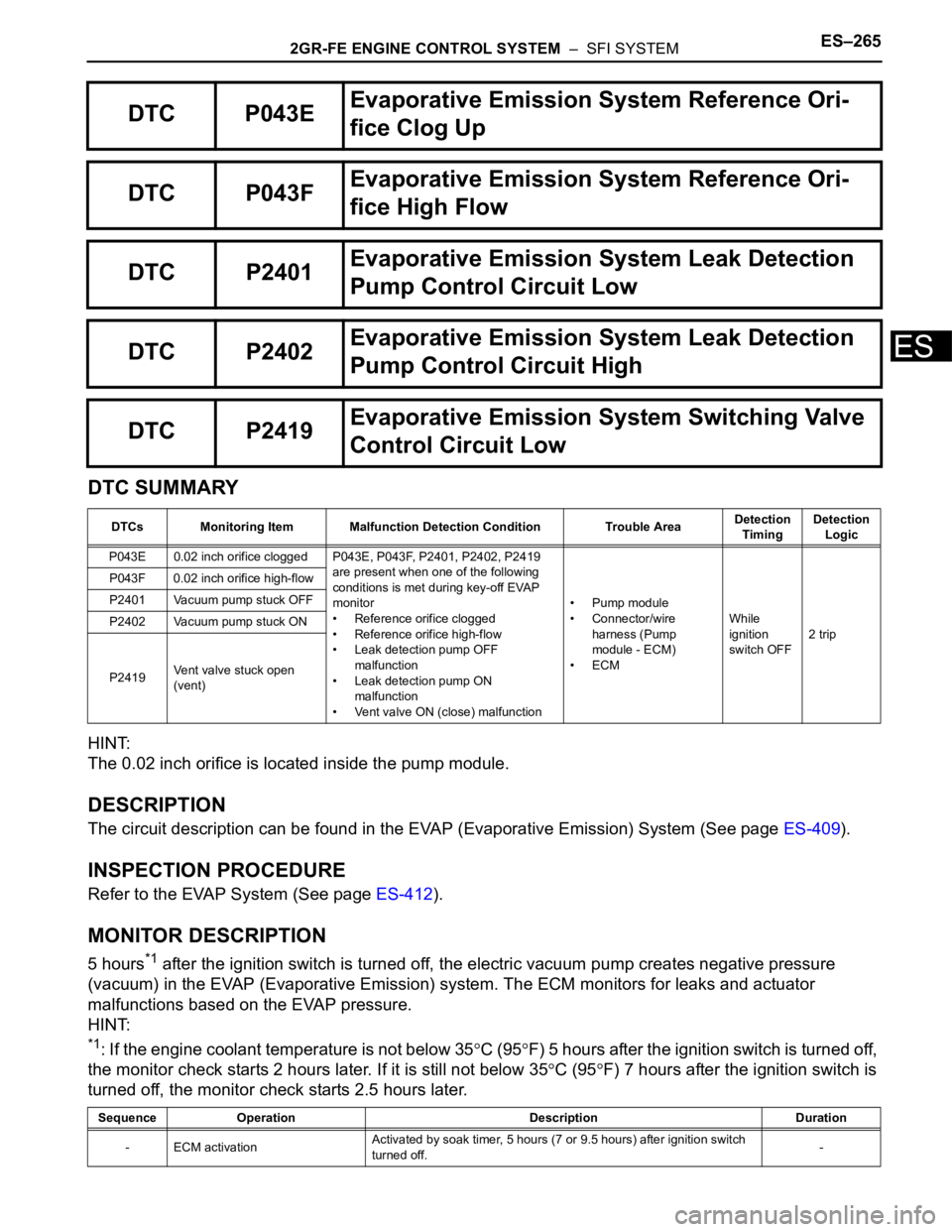
DTC SUMMARY
HINT:
The 0.02 inch orifice is located inside the pump module.
DESCRIPTION
The circuit description can be found in the EVAP (Evaporative Emission) System (See page ES-409).
INSPECTION PROCEDURE
Refer to the EVAP System (See page ES-412).
MONITOR DESCRIPTION
5 hours*1 after the ignition switch is turned off, the electric vacuum pump creates negative pressure
(vacuum) in the EVAP (Evaporative Emission) system. The ECM monitors for leaks and actuator
malfunctions based on the EVAP pressure.
HINT:
*1: If the engine coolant temperature is not below 35C (95F) 5 hours after the ignition switch is turned off,
the monitor check starts 2 hours later. If it is still not below 35
C (95F) 7 hours after the ignition switch is
turned off, the monitor check starts 2.5 hours later.
DTC P043EEvaporative Emission System Reference Ori-
fice Clog Up
DTC P043FEvaporative Emission System Reference Ori-
fice High Flow
DTC P2401Evaporative Emission System Leak Detection
Pump Control Circuit Low
DTC P2402Evaporative Emission System Leak Detection
Pump Control Circuit High
DTC P2419Evaporative Emission System Switching Valve
Control Circuit Low
DTCs Monitoring Item Malfunction Detection Condition Trouble AreaDetection
TimingDetection
Logic
P043E 0.02 inch orifice clogged P043E, P043F, P2401, P2402, P2419
are present when one of the following
conditions is met during key-off EVAP
monitor
• Reference orifice clogged
• Reference orifice high-flow
• Leak detection pump OFF
malfunction
• Leak detection pump ON
malfunction
• Vent valve ON (close) malfunction• Pump module
• Connector/wire
harness (Pump
module - ECM)
•ECMWhile
ignition
switch OFF2 trip P043F 0.02 inch orifice high-flow
P2401 Vacuum pump stuck OFF
P2402 Vacuum pump stuck ON
P2419Vent valve stuck open
(vent)
Sequence Operation Description Duration
- ECM activationActivated by soak timer, 5 hours (7 or 9.5 hours) after ignition switch
turned off.-
Page 561 of 3000

ES–2682GR-FE ENGINE CONTROL SYSTEM – SFI SYSTEM
ESKey-off monitor sequence 1 to 8
1. Atmospheric pressure measurement
2. First reference pressure measurement
3. EVAP canister vent valve close stuck check
4. Vacuum introduction
5. EVAP canister purge valve close stuck check
6. Second reference pressure measurement
7. Leak check
8. Atmospheric pressure measurement
Time after key-off 5 or 7 or 9.5 hours
EVAP pressure sensor malfunction (P0450, P0451,
P0452, P0453)Not detected
EVAP canister purge valve Not operated by scan tool
EVAP canister vent valve Not operated by scan tool
EVAP leak detection pump Not operated by scan tool
Both of the following conditions 1 and 2 are met before
key-off-
1. Duration that vehicle driven 5 minutes or more
2. EVAP purge operation Performed
ECT 4.4 to 35
C (40 to 95F)
IAT 4.4 to 35
C (40 to 95F)
Next sequence is run if the following condition is met: -
Atmospheric pressure change Less than 0.3 kPa (2.25 mmHg) in 1 second
Next sequence is run if all of the following conditions
are met:Conditions 1, 2 and 3
1. EVAP pressure just after reference pressure
measurement-1 kPa (-7.5 mmHg) or less
2. Reference pressure -4.85 to -1.057 kPa (-36.384 to -7.929 mmHg)
3. Reference pressure Saturated within 1 minute
Next sequence is run if the following condition is met: -
EVAP pressure change after vent valve is ON 0.3 kPa (2.25 mmHg) or more
Next sequence is run if the following condition is met: -
EVAP pressure Saturated within 15 minutes
Next sequence is run if the following condition is met: -
EVAP pressure change after purge valve is open 0.3 kPa (2.25 mmHg) or more
Next sequence is run if all of the following conditions
are met:Conditions 1, 2, 3 and 4
1. EVAP pressure just after reference pressure
measurement-1 kPa (-7.5 mmHg) or less
2. Reference pressure -4.85 to -1.057 kPa (-36.384 to -7.929 mmHg)
3. Reference pressure Saturated
4. Difference between first reference pressure and
second reference pressureLess than 0.7 kPa (5.25 mmHg)
Next sequence is run if the following condition is met -
EVAP pressure when vacuum introduction was
completeLower than second reference pressure
EVAP monitor is complete if the following condition is
met:-
Page 563 of 3000

ES–2702GR-FE ENGINE CONTROL SYSTEM – SFI SYSTEM
ES
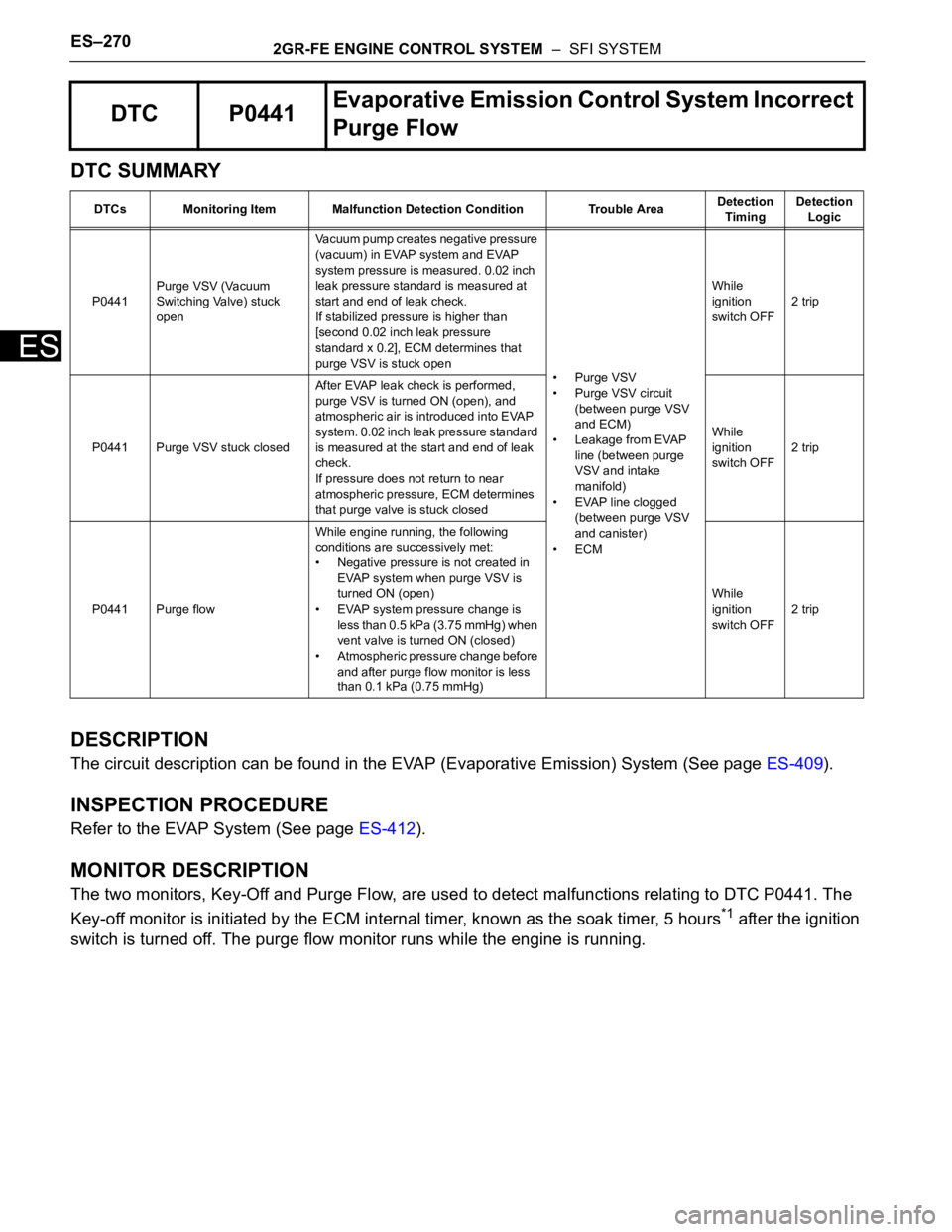
DTC SUMMARY
DESCRIPTION
The circuit description can be found in the EVAP (Evaporative Emission) System (See page ES-409).
INSPECTION PROCEDURE
Refer to the EVAP System (See page ES-412).
MONITOR DESCRIPTION
The two monitors, Key-Off and Purge Flow, are used to detect malfunctions relating to DTC P0441. The
Key-off monitor is initiated by the ECM internal timer, known as the soak timer, 5 hours
*1 after the ignition
switch is turned off. The purge flow monitor runs while the engine is running.
DTC P0441Evaporative Emission Control System Incorrect
Purge Flow
DTCs Monitoring Item Malfunction Detection Condition Trouble AreaDetection
TimingDetection
Logic
P0441Purge VSV (Vacuum
Switching Valve) stuck
openVacuum pump creates negative pressure
(vacuum) in EVAP system and EVAP
system pressure is measured. 0.02 inch
leak pressure standard is measured at
start and end of leak check.
If stabilized pressure is higher than
[second 0.02 inch leak pressure
standard x 0.2], ECM determines that
purge VSV is stuck open
• Purge VSV
• Purge VSV circuit
(between purge VSV
and ECM)
• Leakage from EVAP
line (between purge
VSV and intake
manifold)
• EVAP line clogged
(between purge VSV
and canister)
•ECMWhile
ignition
switch OFF2 trip
P0441 Purge VSV stuck closedAfter EVAP leak check is performed,
purge VSV is turned ON (open), and
atmospheric air is introduced into EVAP
system. 0.02 inch leak pressure standard
is measured at the start and end of leak
check.
If pressure does not return to near
atmospheric pressure, ECM determines
that purge valve is stuck closedWhile
ignition
switch OFF2 trip
P0441 Purge flowWhile engine running, the following
conditions are successively met:
• Negative pressure is not created in
EVAP system when purge VSV is
turned ON (open)
• EVAP system pressure change is
less than 0.5 kPa (3.75 mmHg) when
vent valve is turned ON (closed)
• Atmospheric pressure change before
and after purge flow monitor is less
than 0.1 kPa (0.75 mmHg)While
ignition
switch OFF2 trip