Page 959 of 3000
EM–1502GR-FE ENGINE MECHANICAL – ENGINE UNIT
EM
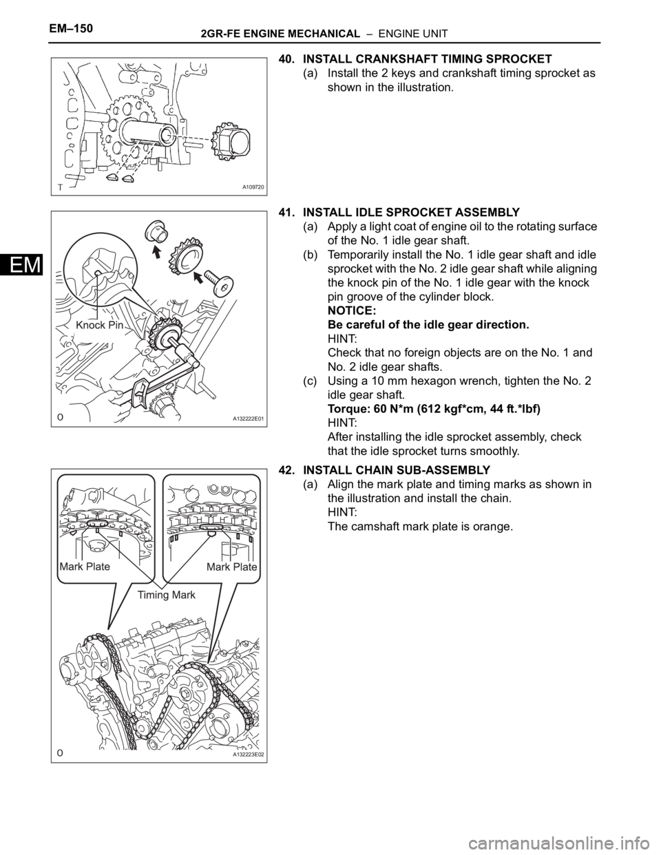
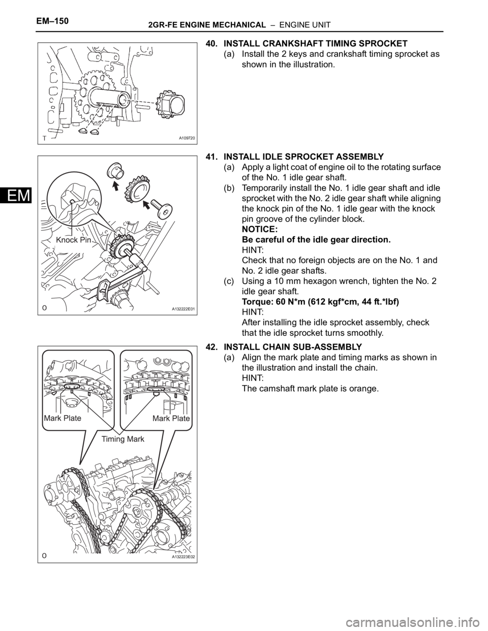
40. INSTALL CRANKSHAFT TIMING SPROCKET
(a) Install the 2 keys and crankshaft timing sprocket as
shown in the illustration.
41. INSTALL IDLE SPROCKET ASSEMBLY
(a) Apply a light coat of engine oil to the rotating surface
of the No. 1 idle gear shaft.
(b) Temporarily install the No. 1 idle gear shaft and idle
sprocket with the No. 2 idle gear shaft while aligning
the knock pin of the No. 1 idle gear with the knock
pin groove of the cylinder block.
NOTICE:
Be careful of the idle gear direction.
HINT:
Check that no foreign objects are on the No. 1 and
No. 2 idle gear shafts.
(c) Using a 10 mm hexagon wrench, tighten the No. 2
idle gear shaft.
Torque: 60 N*m (612 kgf*cm, 44 ft.*lbf)
HINT:
After installing the idle sprocket assembly, check
that the idle sprocket turns smoothly.
42. INSTALL CHAIN SUB-ASSEMBLY
(a) Align the mark plate and timing marks as shown in
the illustration and install the chain.
HINT:
The camshaft mark plate is orange.
A109720
A132222E01
A132223E02
Page 975 of 3000
EM–1662GR-FE ENGINE MECHANICAL – ENGINE UNIT
EM
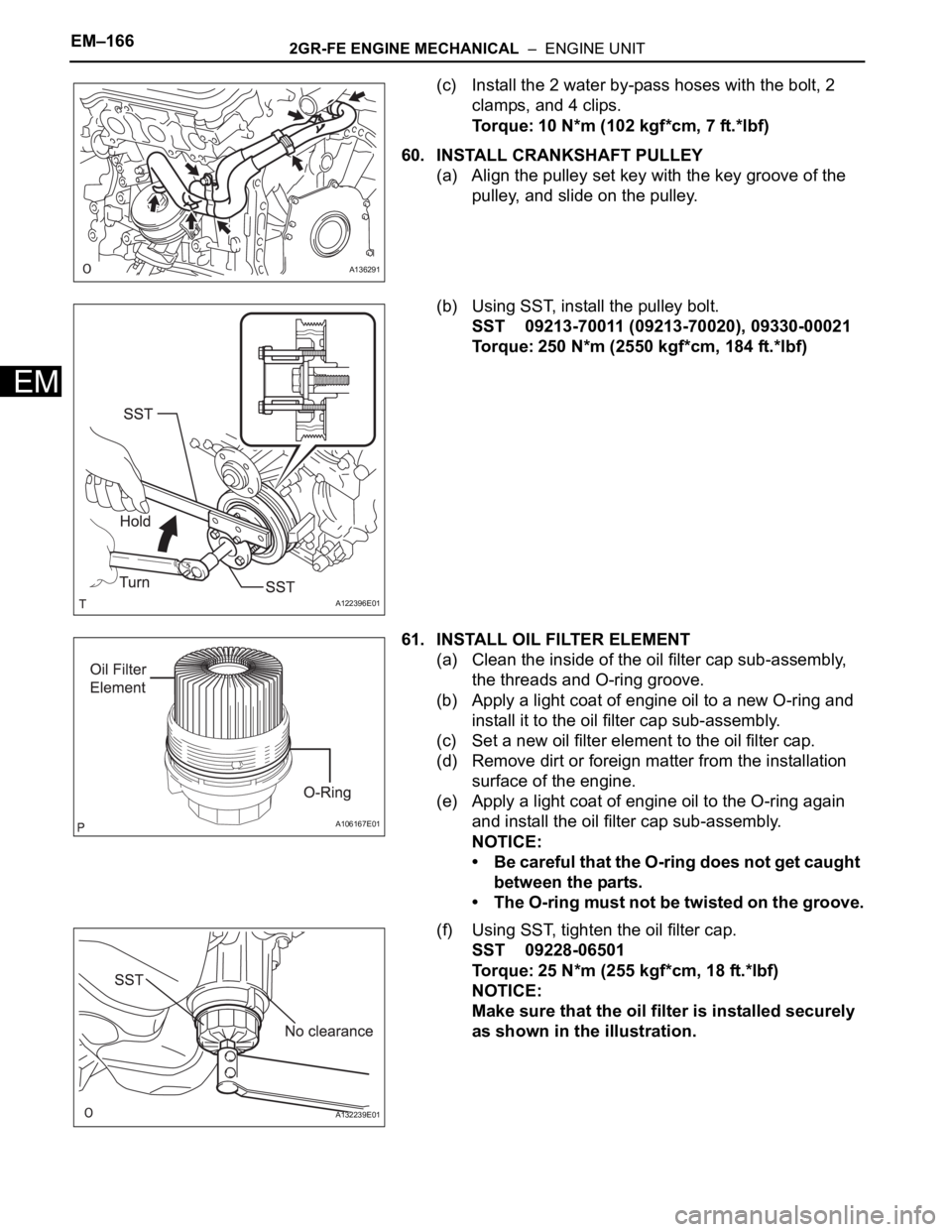
(c) Install the 2 water by-pass hoses with the bolt, 2
clamps, and 4 clips.
Torque: 10 N*m (102 kgf*cm, 7 ft.*lbf)
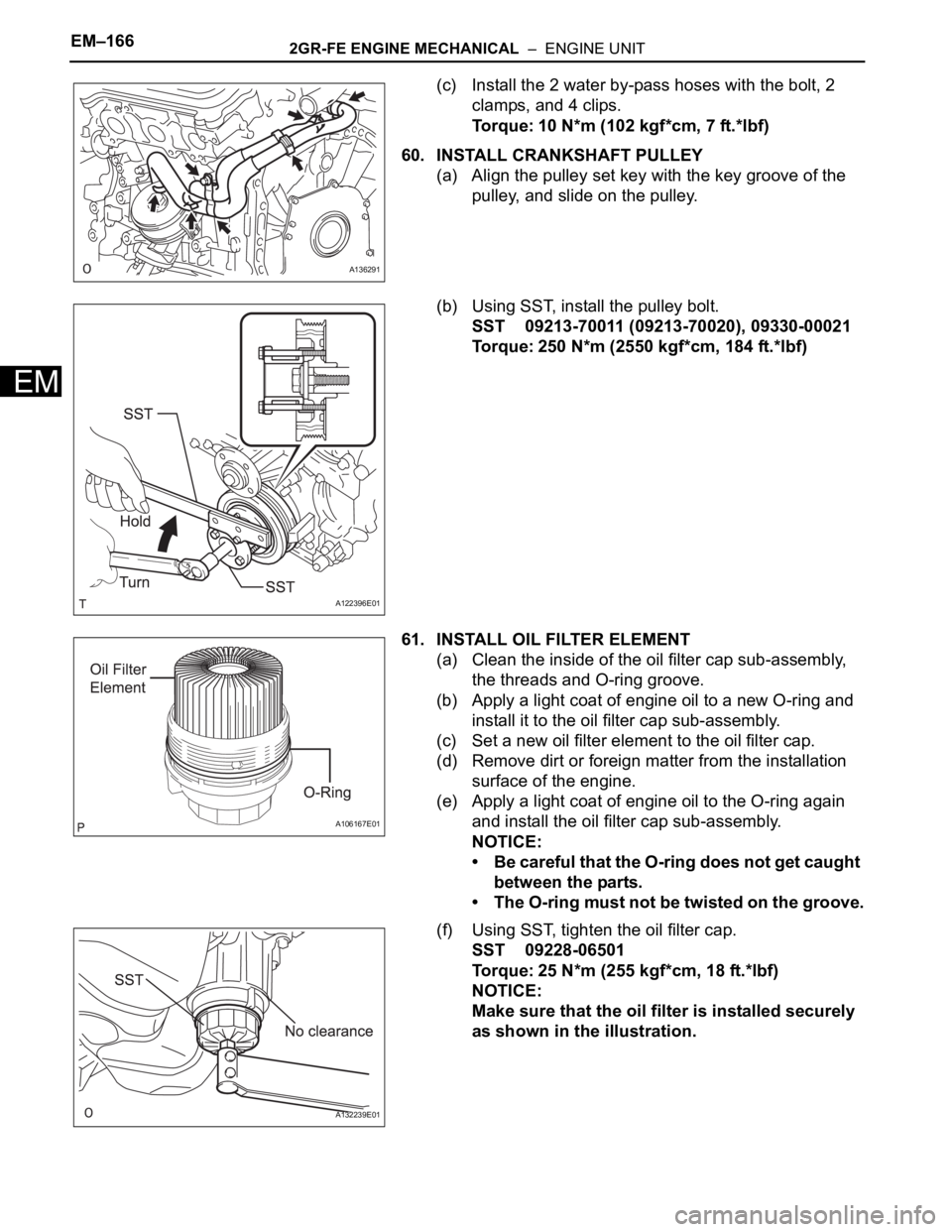
60. INSTALL CRANKSHAFT PULLEY
(a) Align the pulley set key with the key groove of the
pulley, and slide on the pulley.
(b) Using SST, install the pulley bolt.
SST 09213-70011 (09213-70020), 09330-00021
Torque: 250 N*m (2550 kgf*cm, 184 ft.*lbf)
61. INSTALL OIL FILTER ELEMENT
(a) Clean the inside of the oil filter cap sub-assembly,
the threads and O-ring groove.
(b) Apply a light coat of engine oil to a new O-ring and
install it to the oil filter cap sub-assembly.
(c) Set a new oil filter element to the oil filter cap.
(d) Remove dirt or foreign matter from the installation
surface of the engine.
(e) Apply a light coat of engine oil to the O-ring again
and install the oil filter cap sub-assembly.
NOTICE:
• Be careful that the O-ring does not get caught
between the parts.
• The O-ring must not be twisted on the groove.
(f) Using SST, tighten the oil filter cap.
SST 09228-06501
Torque: 25 N*m (255 kgf*cm, 18 ft.*lbf)
NOTICE:
Make sure that the oil filter is installed securely
as shown in the illustration.
A136291
A122396E01
A106167E01
A132239E01
Page 1035 of 3000
EM–882GR-FE ENGINE MECHANICAL – ENGINE UNIT
EM
33. REMOVE IDLE SPROCKET ASSEMBLY
(a) Using a 10 mm hexagon wrench, remove the No. 2
idle gear shaft, idle sprocket assembly and No. 1
idle gear shaft.
34. REMOVE NO. 1 CHAIN VIBRATION DAMPER
(a) Remove the 2 bolts and No. 1 chain vibration
damper.
35. REMOVE NO. 2 CHAIN VIBRATION DAMPER
(a) Remove the 2 No. 2 chain vibration dampers.
36. REMOVE CRANKSHAFT TIMING SPROCKET
(a) Remove the crankshaft timing sprocket from the
crankshaft.
(b) Remove the 2 keys from the crankshaft.
37. REMOVE CAMSHAFT TIMING GEARS AND NO. 2
CHAIN (for Bank 1)
(a) While raising the No. 2 chain tensioner assembly,
insert a pin of
1.0 mm (0.039 in.) into the hole to fix
the No. 2 chain tensioner.
A129695
A129696
A109720
A120651E01
Page 1049 of 3000
EM–1022GR-FE ENGINE MECHANICAL – ENGINE UNIT
EM
(c) Using a micrometer, measure the journal diameter.
Standard journal diameter
If the journal diameter is not as specified, check the
oil clearance.
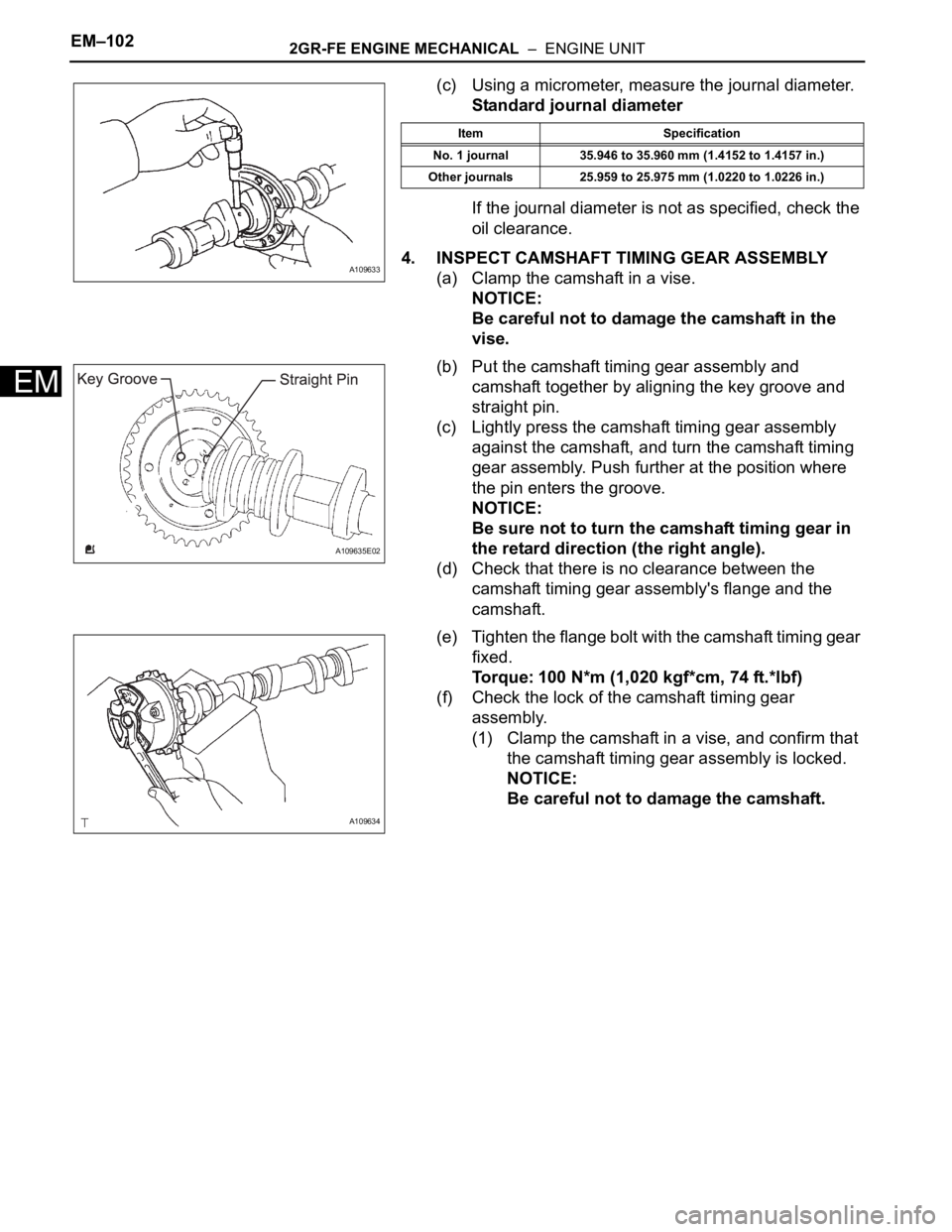
4. INSPECT CAMSHAFT TIMING GEAR ASSEMBLY
(a) Clamp the camshaft in a vise.
NOTICE:
Be careful not to damage the camshaft in the
vise.
(b) Put the camshaft timing gear assembly and
camshaft together by aligning the key groove and
straight pin.
(c) Lightly press the camshaft timing gear assembly
against the camshaft, and turn the camshaft timing
gear assembly. Push further at the position where
the pin enters the groove.
NOTICE:
Be sure not to turn the camshaft timing gear in
the retard direction (the right angle).
(d) Check that there is no clearance between the
camshaft timing gear assembly's flange and the
camshaft.
(e) Tighten the flange bolt with the camshaft timing gear
fixed.
Torque: 100 N*m (1,020 kgf*cm, 74 ft.*lbf)
(f) Check the lock of the camshaft timing gear
assembly.
(1) Clamp the camshaft in a vise, and confirm that
the camshaft timing gear assembly is locked.
NOTICE:
Be careful not to damage the camshaft.
A109633
Item Specification
No. 1 journal 35.946 to 35.960 mm (1.4152 to 1.4157 in.)
Other journals 25.959 to 25.975 mm (1.0220 to 1.0226 in.)
A109635E02
A109634
Page 1051 of 3000
EM–1042GR-FE ENGINE MECHANICAL – ENGINE UNIT
EM
(h) Check for smooth rotation.
(1) Turn the camshaft timing gear assembly within
its movable range (21
) 2 or 3 times, but do not
turn it to the most retarded position. Make sure
that the gear turns smoothly.
NOTICE:
Do not use air pressure to perform the
smooth operation check.
(i) Check the lock in the most retarded position.
(1) Confirm that the camshaft timing gear
assembly is locked at the most retarded
position.
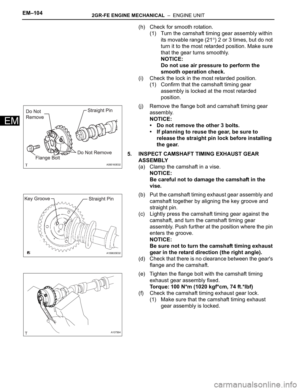
(j) Remove the flange bolt and camshaft timing gear
assembly.
NOTICE:
• Do not remove the other 3 bolts.
• If planning to reuse the gear, be sure to
release the straight pin lock before installing
the gear.
5. INSPECT CAMSHAFT TIMING EXHAUST GEAR
ASSEMBLY
(a) Clamp the camshaft in a vise.
NOTICE:
Be careful not to damage the camshaft in the
vise.
(b) Put the camshaft timing exhaust gear assembly and
camshaft together by aligning the key groove and
straight pin.
(c) Lightly press the camshaft timing gear against the
camshaft, and turn the camshaft timing gear
assembly. Push further at the position where the pin
enters the groove.
NOTICE:
Be sure not to turn the camshaft timing exhaust
gear in the retard direction (the right angle).
(d) Check that there is no clearance between the gear's
flange and the camshaft.
(e) Tighten the flange bolt with the camshaft timing
exhaust gear assembly fixed.
Torque: 100 N*m (1020 kgf*cm, 74 ft.*lbf)
(f) Check the camshaft timing exhaust gear lock.
(1) Make sure that the camshaft timing exhaust
gear assembly is locked.
A095160E02
A109635E02
A107564
Page 1097 of 3000
EM–1502GR-FE ENGINE MECHANICAL – ENGINE UNIT
EM
40. INSTALL CRANKSHAFT TIMING SPROCKET
(a) Install the 2 keys and crankshaft timing sprocket as
shown in the illustration.
41. INSTALL IDLE SPROCKET ASSEMBLY
(a) Apply a light coat of engine oil to the rotating surface
of the No. 1 idle gear shaft.
(b) Temporarily install the No. 1 idle gear shaft and idle
sprocket with the No. 2 idle gear shaft while aligning
the knock pin of the No. 1 idle gear with the knock
pin groove of the cylinder block.
NOTICE:
Be careful of the idle gear direction.
HINT:
Check that no foreign objects are on the No. 1 and
No. 2 idle gear shafts.
(c) Using a 10 mm hexagon wrench, tighten the No. 2
idle gear shaft.
Torque: 60 N*m (612 kgf*cm, 44 ft.*lbf)
HINT:
After installing the idle sprocket assembly, check
that the idle sprocket turns smoothly.
42. INSTALL CHAIN SUB-ASSEMBLY
(a) Align the mark plate and timing marks as shown in
the illustration and install the chain.
HINT:
The camshaft mark plate is orange.
A109720
A132222E01
A132223E02
Page 1113 of 3000
EM–1662GR-FE ENGINE MECHANICAL – ENGINE UNIT
EM
(c) Install the 2 water by-pass hoses with the bolt, 2
clamps, and 4 clips.
Torque: 10 N*m (102 kgf*cm, 7 ft.*lbf)
60. INSTALL CRANKSHAFT PULLEY
(a) Align the pulley set key with the key groove of the
pulley, and slide on the pulley.
(b) Using SST, install the pulley bolt.
SST 09213-70011 (09213-70020), 09330-00021
Torque: 250 N*m (2550 kgf*cm, 184 ft.*lbf)
61. INSTALL OIL FILTER ELEMENT
(a) Clean the inside of the oil filter cap sub-assembly,
the threads and O-ring groove.
(b) Apply a light coat of engine oil to a new O-ring and
install it to the oil filter cap sub-assembly.
(c) Set a new oil filter element to the oil filter cap.
(d) Remove dirt or foreign matter from the installation
surface of the engine.
(e) Apply a light coat of engine oil to the O-ring again
and install the oil filter cap sub-assembly.
NOTICE:
• Be careful that the O-ring does not get caught
between the parts.
• The O-ring must not be twisted on the groove.
(f) Using SST, tighten the oil filter cap.
SST 09228-06501
Torque: 25 N*m (255 kgf*cm, 18 ft.*lbf)
NOTICE:
Make sure that the oil filter is installed securely
as shown in the illustration.
A136291
A122396E01
A106167E01
A132239E01
Page 1325 of 3000
2GR-FE STARTING – STARTERST–11
ST
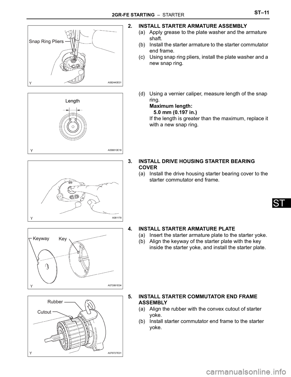
2. INSTALL STARTER ARMATURE ASSEMBLY
(a) Apply grease to the plate washer and the armature
shaft.
(b) Install the starter armature to the starter commutator
end frame.
(c) Using snap ring pliers, install the plate washer and a
new snap ring.
(d) Using a vernier caliper, measure length of the snap
ring.
Maximum length:
5.0 mm (0.197 in.)
If the length is greater than the maximum, replace it
with a new snap ring.
3. INSTALL DRIVE HOUSING STARTER BEARING
COVER
(a) Install the drive housing starter bearing cover to the
starter commutator end frame.
4. INSTALL STARTER ARMATURE PLATE
(a) Insert the starter armature plate to the starter yoke.
(b) Align the keyway of the starter plate with the key
inside the starter yoke, and install the starter plate.
5. INSTALL STARTER COMMUTATOR END FRAME
ASSEMBLY
(a) Align the rubber with the convex cutout of starter
yoke.
(b) Install starter commutator end frame to the starter
yoke.
A082440E01
A058810E18
A081178
A073991E04
A079727E01