2007 TOYOTA SIENNA key
[x] Cancel search: keyPage 700 of 3000
ES–4142GR-FE ENGINE CONTROL SYSTEM – SFI SYSTEM
ES
(2) Turn the ignition switch off and wait for 6 hours (8 or 10.5 hours).
HINT:
Do not start the engine until checking MONITOR STATUS. If the engine is started, the steps
described above must be repeated.
(c) Monitor Status
(1) Connect the intelligent tester to the DLC3.
(2) Turn the ignition switch to the ON position and turn the tester on.
(3) Select the following menu items: DIAGNOSIS / ENHANCED OBD II / MONITOR STATUS.
(4) Check the "Monitor Status" displayed on the tester.
HINT:
If INCMP is displayed, the monitor is not completed. Make sure that the preconditions have
been met, and perform "Monitor Conditions" again.
2. PURGE FLOW MONITOR CONFIRMATION (P0441)
HINT:
Perform this monitor confirmation after the Key-Off Monitor Confirmation shows COMPL (complete).
(a) Preconditions
The monitor will not run unless:
• The vehicle has been driven for 10 minutes or more (in a city area or on a freeway)
• The ECT is between 4.4
C and 35C (40F and 95F)
• The IAT is between 4.4
C and 35C (40F and 95F)
(b) Monitor Conditions
(1) Release the pressure from the fuel tank by removing and reinstalling the fuel tank cap.
(2) Warm the engine up until the ECT reaches more than 75
C (167F).
(3) Increase the engine speed to 3000 rpm once.
(4) Allow the engine to idle and turn the A/C ON for 1 minute.
(c) Monitor Status
(1) Turn the ignition switch off.
(2) Connect the intelligent tester to the DLC3.
(3) Turn the ignition switch to the ON position and turn the tester on.
(4) Select the following menu items: DIAGNOSIS / ENHANCED OBD II / MONITOR STATUS.
(5) Check the "Monitor Status" displayed on the tester.
HINT:
If INCMP is displayed, the monitor is not completed. Make sure that the preconditions have
been met, and perform "Monitor Conditions" again.
MONITOR RESULT
Refer to Checking Monitor Status for detailed information (See page ES-19).
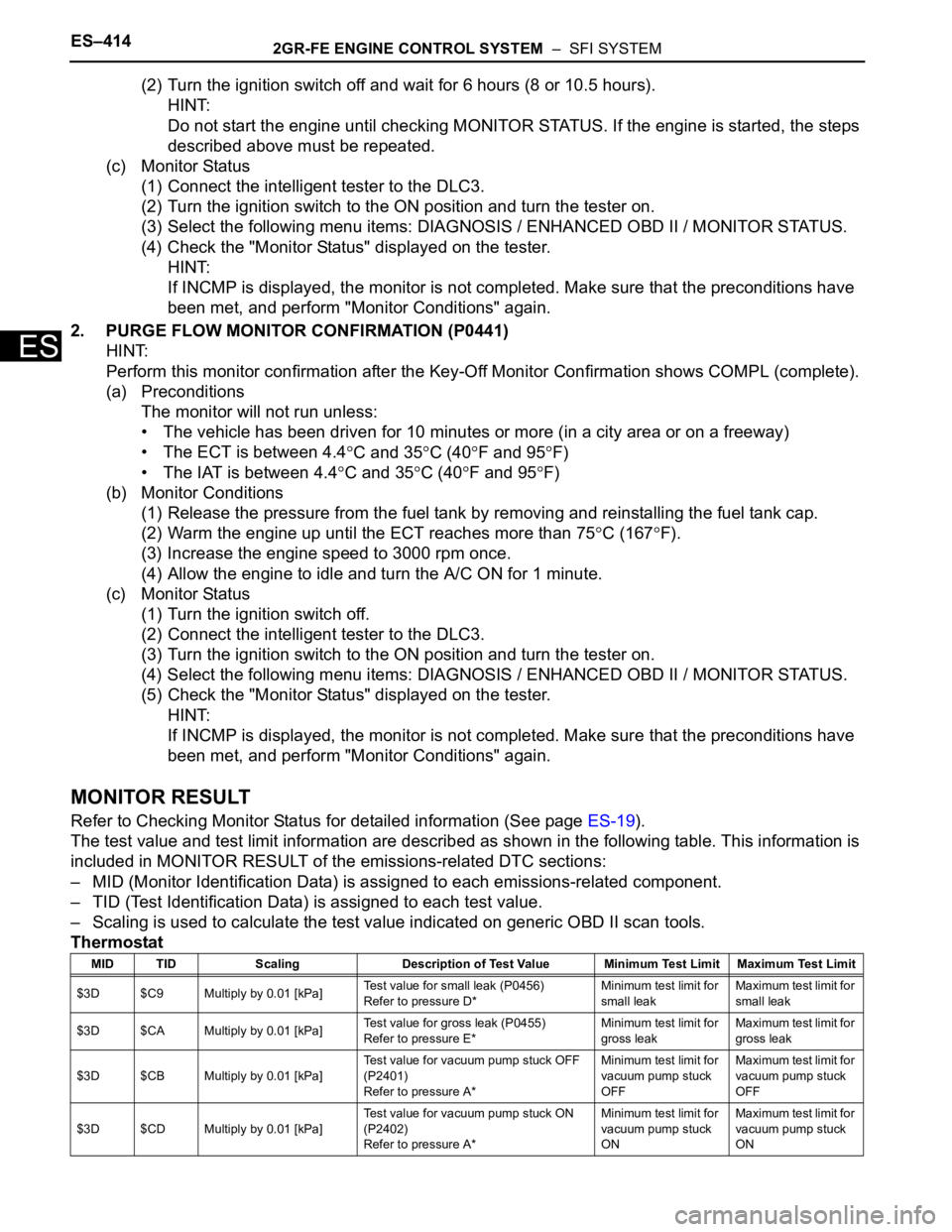
The test value and test limit information are described as shown in the following table. This information is
included in MONITOR RESULT of the emissions-related DTC sections:
– MID (Monitor Identification Data) is assigned to each emissions-related component.
– TID (Test Identification Data) is assigned to each test value.
– Scaling is used to calculate the test value indicated on generic OBD II scan tools.
Thermostat
MID TID Scaling Description of Test Value Minimum Test Limit Maximum Test Limit
$3D $C9 Multiply by 0.01 [kPa]Test value for small leak (P0456)
Refer to pressure D*Minimum test limit for
small leakMaximum test limit for
small leak
$3D $CA Multiply by 0.01 [kPa]Test value for gross leak (P0455)
Refer to pressure E*Minimum test limit for
gross leakMaximum test limit for
gross leak
$3D $CB Multiply by 0.01 [kPa]Test value for vacuum pump stuck OFF
(P2401)
Refer to pressure A*Minimum test limit for
vacuum pump stuck
OFFMaximum test limit for
vacuum pump stuck
OFF
$3D $CD Multiply by 0.01 [kPa]Test value for vacuum pump stuck ON
(P2402)
Refer to pressure A*Minimum test limit for
vacuum pump stuck
ONMaximum test limit for
vacuum pump stuck
ON
Page 704 of 3000
ES–4182GR-FE ENGINE CONTROL SYSTEM – SFI SYSTEM
ES
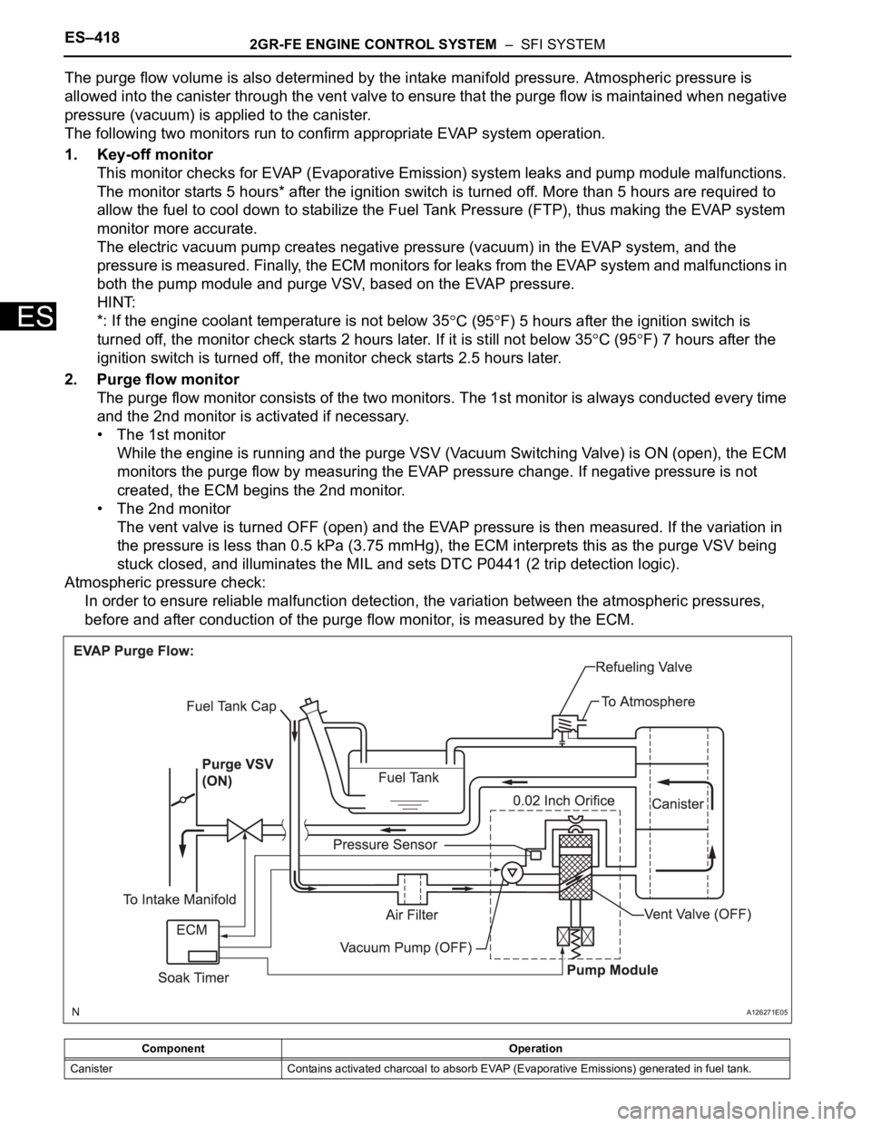
The purge flow volume is also determined by the intake manifold pressure. Atmospheric pressure is
allowed into the canister through the vent valve to ensure that the purge flow is maintained when negative
pressure (vacuum) is applied to the canister.
The following two monitors run to confirm appropriate EVAP system operation.
1. Key-off monitor
This monitor checks for EVAP (Evaporative Emission) system leaks and pump module malfunctions.
The monitor starts 5 hours* after the ignition switch is turned off. More than 5 hours are required to
allow the fuel to cool down to stabilize the Fuel Tank Pressure (FTP), thus making the EVAP system
monitor more accurate.
The electric vacuum pump creates negative pressure (vacuum) in the EVAP system, and the
pressure is measured. Finally, the ECM monitors for leaks from the EVAP system and malfunctions in
both the pump module and purge VSV, based on the EVAP pressure.
HINT:
*: If the engine coolant temperature is not below 35
C (95F) 5 hours after the ignition switch is
turned off, the monitor check starts 2 hours later. If it is still not below 35
C (95F) 7 hours after the
ignition switch is turned off, the monitor check starts 2.5 hours later.
2. Purge flow monitor
The purge flow monitor consists of the two monitors. The 1st monitor is always conducted every time
and the 2nd monitor is activated if necessary.
• The 1st monitor
While the engine is running and the purge VSV (Vacuum Switching Valve) is ON (open), the ECM
monitors the purge flow by measuring the EVAP pressure change. If negative pressure is not
created, the ECM begins the 2nd monitor.
• The 2nd monitor
The vent valve is turned OFF (open) and the EVAP pressure is then measured. If the variation in
the pressure is less than 0.5 kPa (3.75 mmHg), the ECM interprets this as the purge VSV being
stuck closed, and illuminates the MIL and sets DTC P0441 (2 trip detection logic).
Atmospheric pressure check:
In order to ensure reliable malfunction detection, the variation between the atmospheric pressures,
before and after conduction of the purge flow monitor, is measured by the ECM.
Component Operation
Canister Contains activated charcoal to absorb EVAP (Evaporative Emissions) generated in fuel tank.
A126271E05
Page 755 of 3000
2GR-FE ENGINE CONTROL SYSTEM – SFI SYSTEMES–469
ES
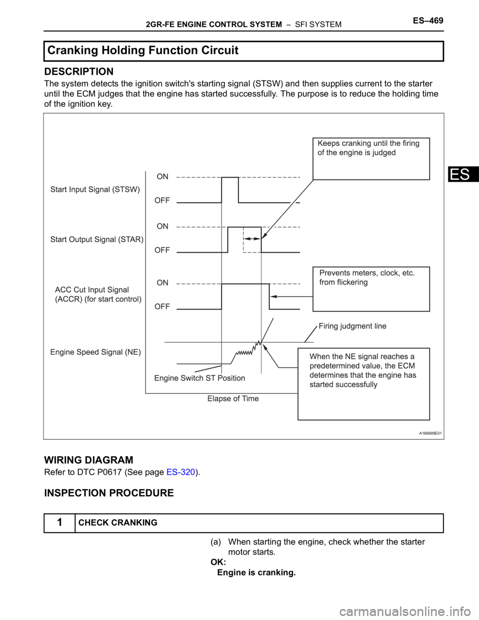
DESCRIPTION
The system detects the ignition switch's starting signal (STSW) and then supplies current to the starter
until the ECM judges that the engine has started successfully. The purpose is to reduce the holding time
of the ignition key.
WIRING DIAGRAM
Refer to DTC P0617 (See page ES-320).
INSPECTION PROCEDURE
(a) When starting the engine, check whether the starter
motor starts.
OK:
Engine is cranking.
Cranking Holding Function Circuit
1CHECK CRANKING
A166695E01
Page 803 of 3000
2GR-FE ENGINE CONTROL SYSTEM – SFI SYSTEMES–27
ES
Contents:
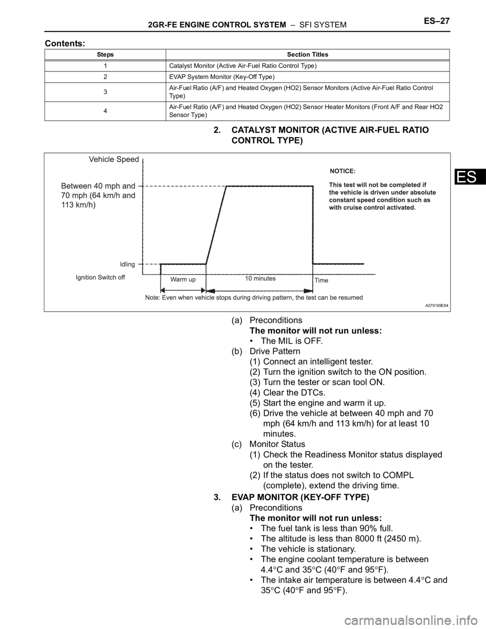
2. CATALYST MONITOR (ACTIVE AIR-FUEL RATIO
CONTROL TYPE)
(a) Preconditions
The monitor will not run unless:
• The MIL is OFF.
(b) Drive Pattern
(1) Connect an intelligent tester.
(2) Turn the ignition switch to the ON position.
(3) Turn the tester or scan tool ON.
(4) Clear the DTCs.
(5) Start the engine and warm it up.
(6) Drive the vehicle at between 40 mph and 70
mph (64 km/h and 113 km/h) for at least 10
minutes.
(c) Monitor Status
(1) Check the Readiness Monitor status displayed
on the tester.
(2) If the status does not switch to COMPL
(complete), extend the driving time.
3. EVAP MONITOR (KEY-OFF TYPE)
(a) Preconditions
The monitor will not run unless:
• The fuel tank is less than 90% full.
• The altitude is less than 8000 ft (2450 m).
• The vehicle is stationary.
• The engine coolant temperature is between
4.4
C and 35C (40F and 95F).
• The intake air temperature is between 4.4
C and
35
C (40F and 95F).
Steps Section Titles
1 Catalyst Monitor (Active Air-Fuel Ratio Control Type)
2 EVAP System Monitor (Key-Off Type)
3Air-Fuel Ratio (A/F) and Heated Oxygen (HO2) Sensor Monitors (Active Air-Fuel Ratio Control
Ty p e )
4Air-Fuel Ratio (A/F) and Heated Oxygen (HO2) Sensor Heater Monitors (Front A/F and Rear HO2
Sensor Type)
A079199E84
Page 832 of 3000

ES–482GR-FE ENGINE CONTROL SYSTEM – SFI SYSTEM
ES
O2FT B2 S2 Fuel trim at heated oxygen sensor Same as SHORT FT #2
AF FT B1 S1 Fuel trim at A/F sensor -
AF FT B2 S1 Fuel trim at A/F sensor -
CAT TEMP B1 S1 Catalyst temperature -
CAT TEMP B2 S1 Catalyst temperature -
CAT TEMP B1 S2 Catalyst temperature -
CAT TEMP B2 S2 Catalyst temperature -
S O2S B1 S2 Heated oxygen sensor impedance (Sensor 2) -
S O2S B2 S2 Heated oxygen sensor impedance (Sensor 2) -
INI COOL TEMP Initial engine coolant temperature -
INI INTAKE TEMP Initial intake air temperature -
INJ VOL Injection volume -
STARTER SIG Starter signal -
PS SW Power steering signal -
PS SIGNAL Power steering signal (history)This signal status usually ON until ignition
switch turned off
CTP SW Closed throttle position switch -
A/C SIGNAL A/C signal -
ELECT LOAD SIG Electrical load signal -
STOP LIGHT SW Stop light switch -
BATTERY VOLTAGE Battery voltage -
ATM PRESSURE Atmospheric pressure -
FUEL PMP SP CTL Fuel pump speed control status -
ACIS VSVVSV for Air Intake Control Induction System
(AICS)-
VVT CTRL B2 VVT control (bank 2 Intake side) status -
EVAP (Purge) VSV EVAP purge VSV -
FUEL PUMP/SPD Fuel pump speed statusVSV for EVAP controlled by ECM (ground
side duty control)
VACUUM PUMP Key-off EVAP system pump status -
EVAP VENT VAL Key-off EVAP system vent valve status -
FAN MOTOR Electric fan motor -
TC/TE1 TC and TE1 terminals of DLC3 -
ACM ACM control status -
VVTL AIM ANGL #1 VVT aim angle -
VVT CHNG ANGL #1 VVT change angle -
VVT OCV DUTY B1 VVT OCV operation duty -
VVT EX HOLD B1VVT exhaust hold duty ratio learning value
(bank 1 Exhaust side)-
VVT EX CHG ANG1 VVT change angle (bank 1 Exhaust side) -
VVT EX OCV D B1VVT OCV (bank 1 Exhaust side) operation
duty-
VVTL AIM ANGL#2 VVT aim angle (bank 2 Intake side) -
VVT CHNG ANGL#2 VVT change angle (bank 2 Intake side) -
VVT OCV DUTY B2 VVT OCV (bank 2 Intake side) operation duty -
VVT EX HOLD B2VVT exhaust hold duty ratio learning value
(bank 2 Exhaust side)-
VVT EX CHG ANG2 VVT change angle (bank 2 Exhaust side) -
VVT EX OCV D B2VVT OCV (bank 2 Exhaust side) operation
duty- LABEL
(Intelligent Tester Display)Measurement Item Diagnostic Note
Page 893 of 3000
EM–882GR-FE ENGINE MECHANICAL – ENGINE UNIT
EM
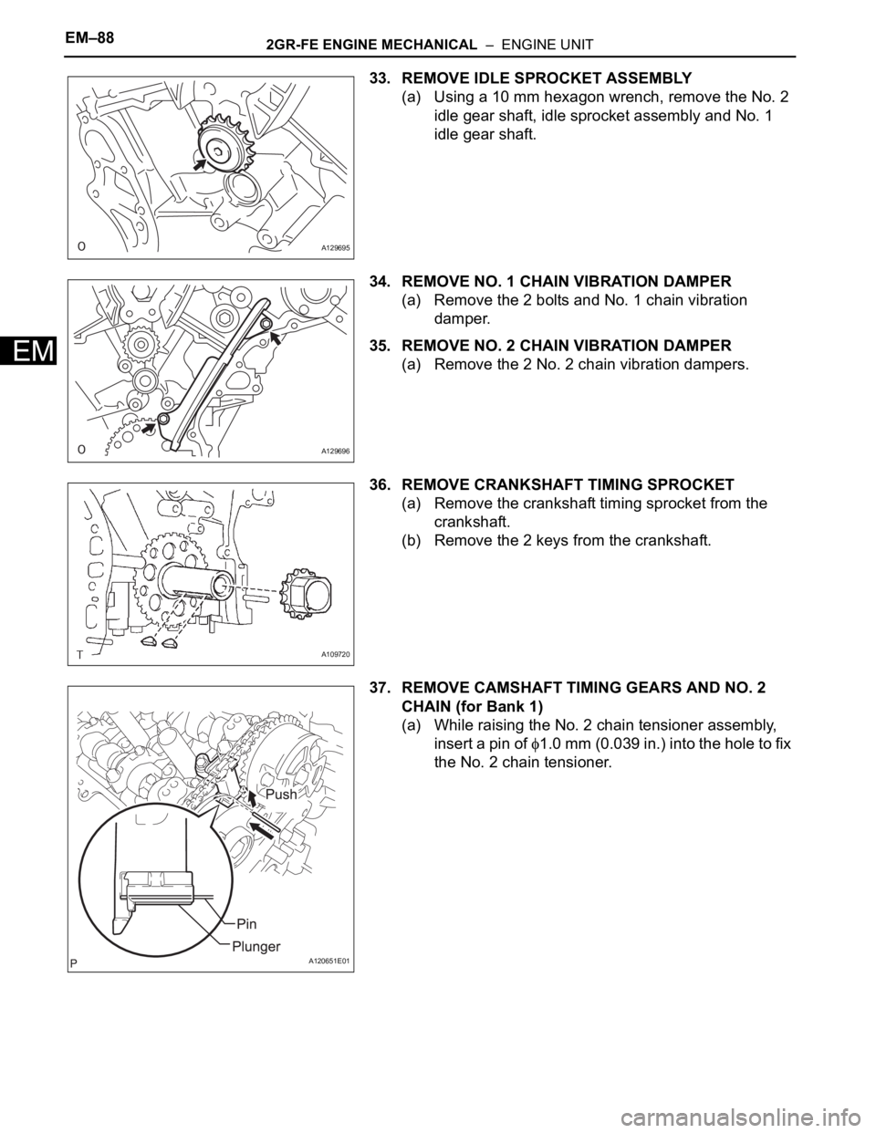
33. REMOVE IDLE SPROCKET ASSEMBLY
(a) Using a 10 mm hexagon wrench, remove the No. 2
idle gear shaft, idle sprocket assembly and No. 1
idle gear shaft.
34. REMOVE NO. 1 CHAIN VIBRATION DAMPER
(a) Remove the 2 bolts and No. 1 chain vibration
damper.
35. REMOVE NO. 2 CHAIN VIBRATION DAMPER
(a) Remove the 2 No. 2 chain vibration dampers.
36. REMOVE CRANKSHAFT TIMING SPROCKET
(a) Remove the crankshaft timing sprocket from the
crankshaft.
(b) Remove the 2 keys from the crankshaft.
37. REMOVE CAMSHAFT TIMING GEARS AND NO. 2
CHAIN (for Bank 1)
(a) While raising the No. 2 chain tensioner assembly,
insert a pin of
1.0 mm (0.039 in.) into the hole to fix
the No. 2 chain tensioner.
A129695
A129696
A109720
A120651E01
Page 907 of 3000
EM–1022GR-FE ENGINE MECHANICAL – ENGINE UNIT
EM
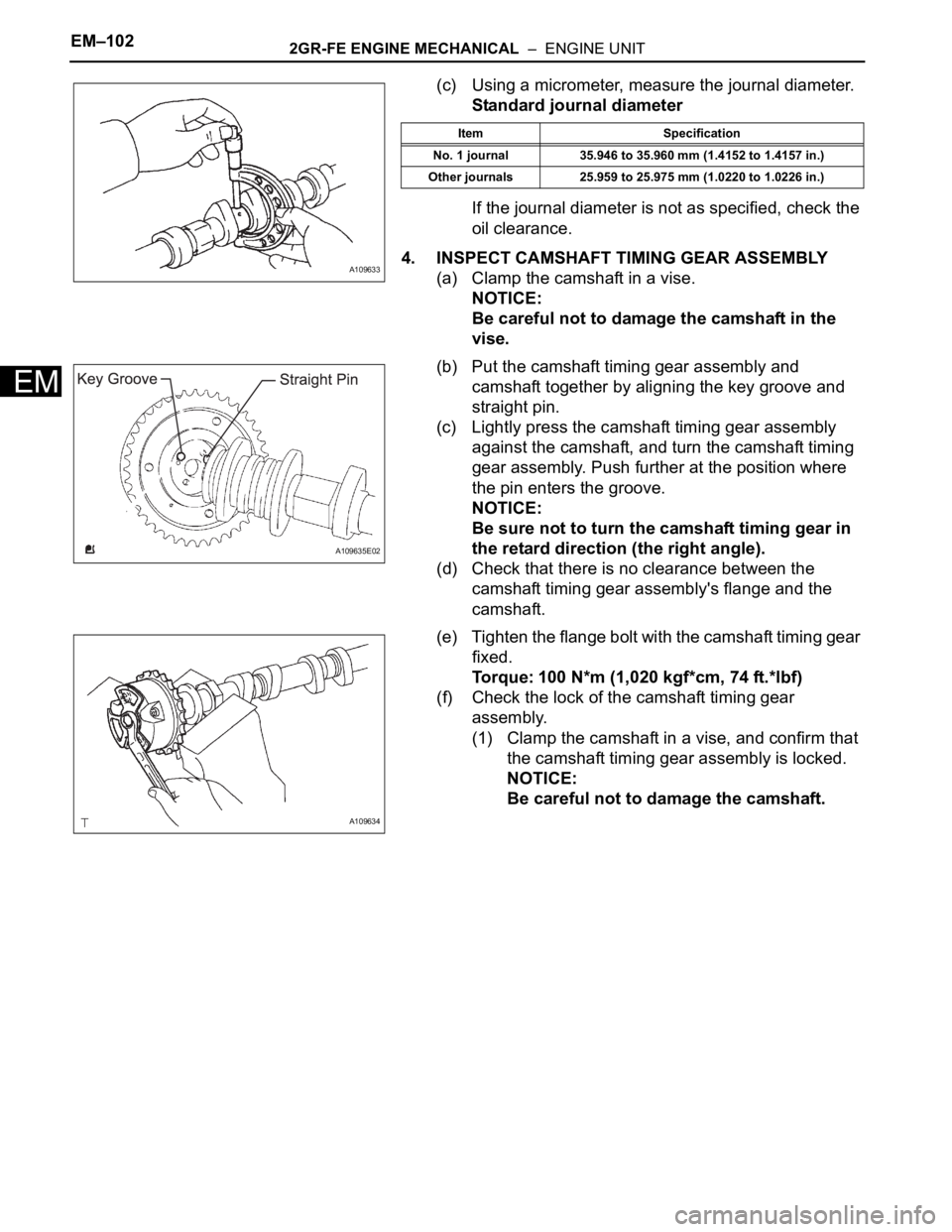
(c) Using a micrometer, measure the journal diameter.
Standard journal diameter
If the journal diameter is not as specified, check the
oil clearance.
4. INSPECT CAMSHAFT TIMING GEAR ASSEMBLY
(a) Clamp the camshaft in a vise.
NOTICE:
Be careful not to damage the camshaft in the
vise.
(b) Put the camshaft timing gear assembly and
camshaft together by aligning the key groove and
straight pin.
(c) Lightly press the camshaft timing gear assembly
against the camshaft, and turn the camshaft timing
gear assembly. Push further at the position where
the pin enters the groove.
NOTICE:
Be sure not to turn the camshaft timing gear in
the retard direction (the right angle).
(d) Check that there is no clearance between the
camshaft timing gear assembly's flange and the
camshaft.
(e) Tighten the flange bolt with the camshaft timing gear
fixed.
Torque: 100 N*m (1,020 kgf*cm, 74 ft.*lbf)
(f) Check the lock of the camshaft timing gear
assembly.
(1) Clamp the camshaft in a vise, and confirm that
the camshaft timing gear assembly is locked.
NOTICE:
Be careful not to damage the camshaft.
A109633
Item Specification
No. 1 journal 35.946 to 35.960 mm (1.4152 to 1.4157 in.)
Other journals 25.959 to 25.975 mm (1.0220 to 1.0226 in.)
A109635E02
A109634
Page 909 of 3000
EM–1042GR-FE ENGINE MECHANICAL – ENGINE UNIT
EM
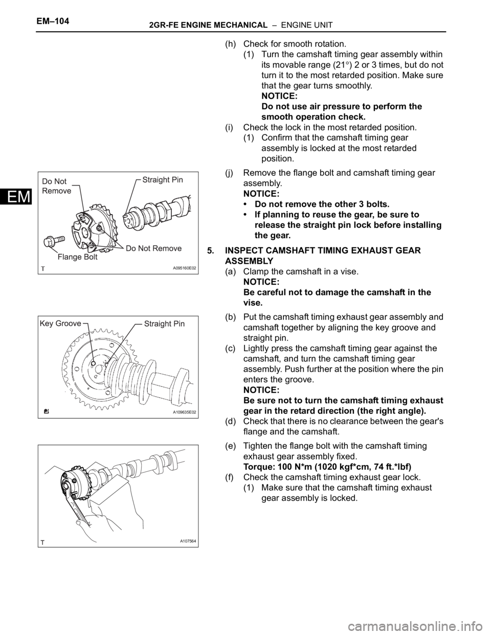
(h) Check for smooth rotation.
(1) Turn the camshaft timing gear assembly within
its movable range (21
) 2 or 3 times, but do not
turn it to the most retarded position. Make sure
that the gear turns smoothly.
NOTICE:
Do not use air pressure to perform the
smooth operation check.
(i) Check the lock in the most retarded position.
(1) Confirm that the camshaft timing gear
assembly is locked at the most retarded
position.
(j) Remove the flange bolt and camshaft timing gear
assembly.
NOTICE:
• Do not remove the other 3 bolts.
• If planning to reuse the gear, be sure to
release the straight pin lock before installing
the gear.
5. INSPECT CAMSHAFT TIMING EXHAUST GEAR
ASSEMBLY
(a) Clamp the camshaft in a vise.
NOTICE:
Be careful not to damage the camshaft in the
vise.
(b) Put the camshaft timing exhaust gear assembly and
camshaft together by aligning the key groove and
straight pin.
(c) Lightly press the camshaft timing gear against the
camshaft, and turn the camshaft timing gear
assembly. Push further at the position where the pin
enters the groove.
NOTICE:
Be sure not to turn the camshaft timing exhaust
gear in the retard direction (the right angle).
(d) Check that there is no clearance between the gear's
flange and the camshaft.
(e) Tighten the flange bolt with the camshaft timing
exhaust gear assembly fixed.
Torque: 100 N*m (1020 kgf*cm, 74 ft.*lbf)
(f) Check the camshaft timing exhaust gear lock.
(1) Make sure that the camshaft timing exhaust
gear assembly is locked.
A095160E02
A109635E02
A107564