Page 1831 of 3000
AX–142U151F AUTOMATIC TRANSAXLE – SHIFT LOCK SYSTEM
AX
SHIFT LOCK SYSTEM
ON-VEHICLE INSPECTION
1. CHECK SHIFT LOCK OPERATION
(a) Move the shift lever to the P position.
(b) Turn the ignition switch to the LOCK position.
(c) Check that the shift lever cannot be moved to any
position other than P.
(d) Turn the ignition switch to the on position, depress
the brake pedal and check that the shift lever can be
moved to another position. If operation can not be
done as specified, inspect the shift lock control unit.
2. CHECK SHIFT LOCK RELEASE BUTTON
OPERATION
(a) Using a small screwdriver, remove the shift lock
release cover.
(b) When operating the shift lever with the shift lock
release button pressed, check that the lever can be
moved to any position other than P.
If operation can not be done as specified, check the
shift lever assembly installation condition.
3. CHECK KEY INTERLOCK OPERATION
(a) Turn the ignition switch to the ON position.
(b) Depress the brake pedal and move the shift lever to
any position other than P.
(c) Check that the ignition key cannot be turned to the
LOCK position.
(d) Move the shift lever to the P position, turn the
ignition key to the LOCK position and check that the
ignition key can be removed.
If operation cannot be done as specified, inspect the
shift lock control unit.
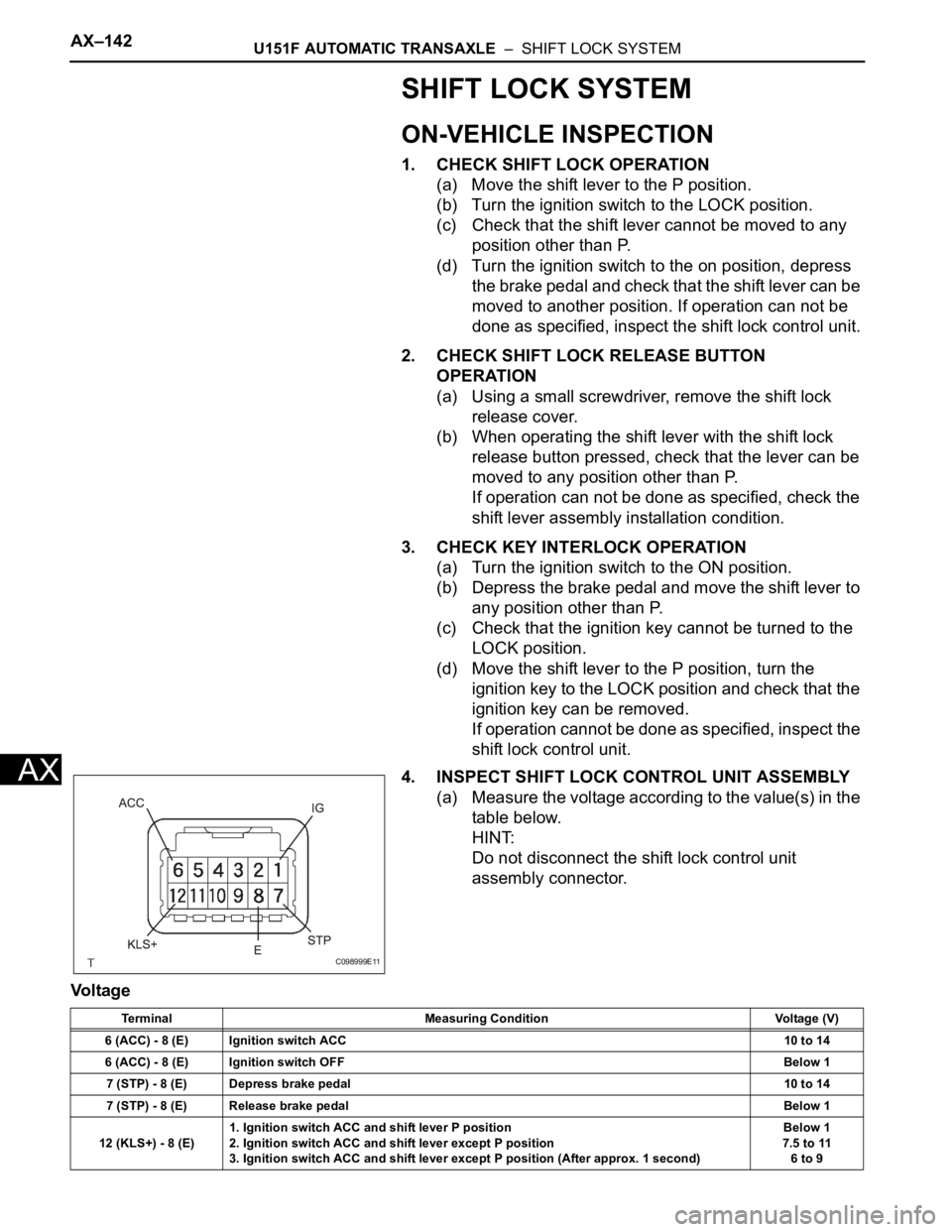
4. INSPECT SHIFT LOCK CONTROL UNIT ASSEMBLY
(a) Measure the voltage according to the value(s) in the
table below.
HINT:
Do not disconnect the shift lock control unit
assembly connector.
Voltage
C098999E11
Terminal Measuring Condition Voltage (V)
6 (ACC) - 8 (E) Ignition switch ACC10 to 14
6 (ACC) - 8 (E) Ignition switch OFFBelow 1
7 (STP) - 8 (E) Depress brake pedal10 to 14
7 (STP) - 8 (E) Release brake pedalBelow 1
12 (KLS+) - 8 (E)1. Ignition switch ACC and shift lever P position
2. Ignition switch ACC and shift lever except P position
3. Ignition switch ACC and shift lever except P position (After approx. 1 second)Below 1
7.5 to 11
6 to 9
Page 1832 of 3000
U151F AUTOMATIC TRANSAXLE – SHIFT LOCK SYSTEMAX–143
AX
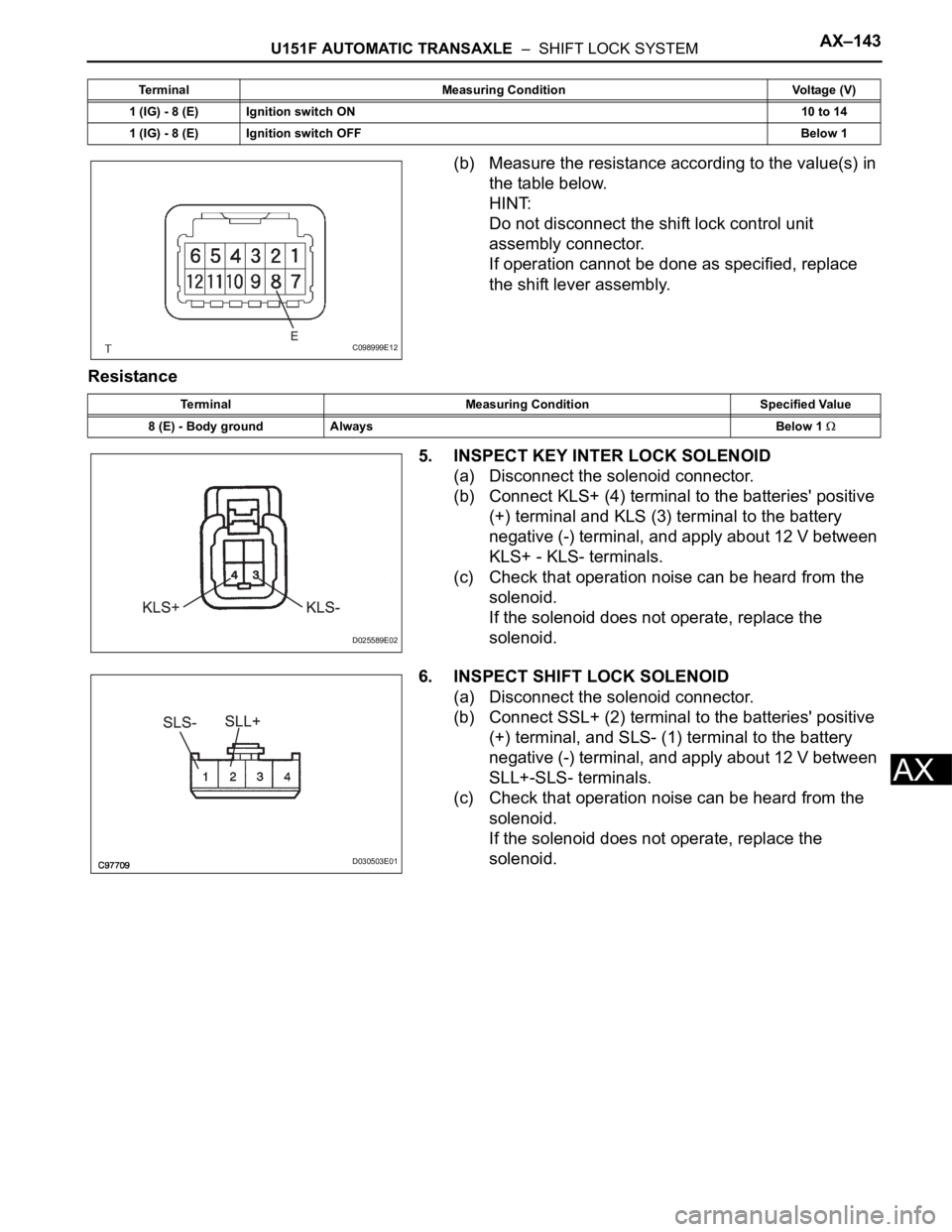
(b) Measure the resistance according to the value(s) in
the table below.
HINT:
Do not disconnect the shift lock control unit
assembly connector.
If operation cannot be done as specified, replace
the shift lever assembly.
Resistance
5. INSPECT KEY INTER LOCK SOLENOID
(a) Disconnect the solenoid connector.
(b) Connect KLS+ (4) terminal to the batteries' positive
(+) terminal and KLS (3) terminal to the battery
negative (-) terminal, and apply about 12 V between
KLS+ - KLS- terminals.
(c) Check that operation noise can be heard from the
solenoid.
If the solenoid does not operate, replace the
solenoid.
6. INSPECT SHIFT LOCK SOLENOID
(a) Disconnect the solenoid connector.
(b) Connect SSL+ (2) terminal to the batteries' positive
(+) terminal, and SLS- (1) terminal to the battery
negative (-) terminal, and apply about 12 V between
SLL+-SLS- terminals.
(c) Check that operation noise can be heard from the
solenoid.
If the solenoid does not operate, replace the
solenoid.
1 (IG) - 8 (E) Ignition switch ON10 to 14
1 (IG) - 8 (E) Ignition switch OFFBelow 1 Terminal Measuring Condition Voltage (V)
C098999E12
Terminal Measuring Condition Specified Value
8 (E) - Body ground AlwaysBelow 1
D025589E02
D030503E01
Page 1844 of 3000
U151F AUTOMATIC TRANSAXLE – SHIFT LEVERAX–153
AX
5. INSTALL POSITION INDICATOR HOUSING
ASSEMBLY
(a) install the position indicator housing assembly to the
instrument cluster finish panel assembly center.
6. INSTALL SHIFT LEVER KNOB SUB-ASSEMBLY
(a) install the shift lever knob sub-assembly.
7. ADJUST SHIFT LEVER POSITION
HINT:
(See page AX-149)
8. INSPECT SHIFT LEVER POSITION
HINT:
(See page AX-148)
9. INSPECT KEY INTER LOCK OPERATION
HINT:
(See page AX-142)
10. INSPECT SHIFT LOCK OPERATION
HINT:
(See page AX-142)
11. INSPECT SHIFT LOCK RELEASE BUTTON
OPERATION
HINT:
(See page AX-142)
C086303E02
C086302E02
Page 2672 of 3000
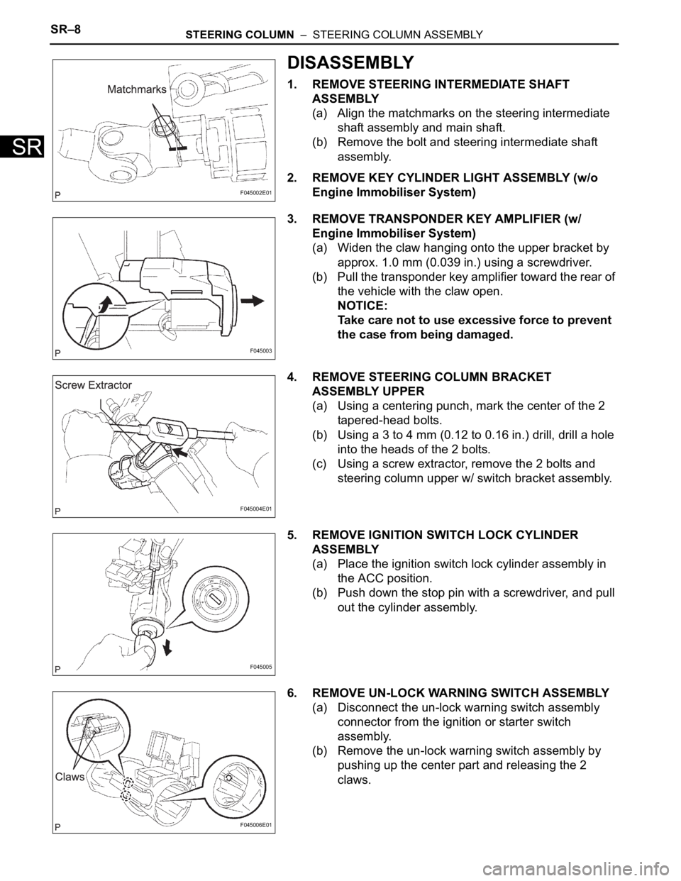
SR–8STEERING COLUMN – STEERING COLUMN ASSEMBLY
SR
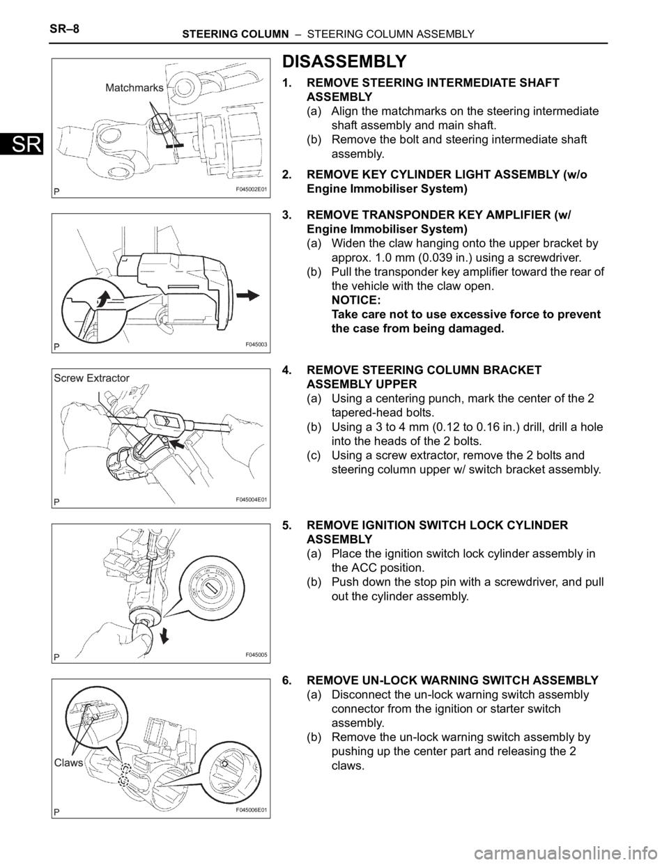
DISASSEMBLY
1. REMOVE STEERING INTERMEDIATE SHAFT
ASSEMBLY
(a) Align the matchmarks on the steering intermediate
shaft assembly and main shaft.
(b) Remove the bolt and steering intermediate shaft
assembly.
2. REMOVE KEY CYLINDER LIGHT ASSEMBLY (w/o
Engine Immobiliser System)
3. REMOVE TRANSPONDER KEY AMPLIFIER (w/
Engine Immobiliser System)
(a) Widen the claw hanging onto the upper bracket by
approx. 1.0 mm (0.039 in.) using a screwdriver.
(b) Pull the transponder key amplifier toward the rear of
the vehicle with the claw open.
NOTICE:
Take care not to use excessive force to prevent
the case from being damaged.
4. REMOVE STEERING COLUMN BRACKET
ASSEMBLY UPPER
(a) Using a centering punch, mark the center of the 2
tapered-head bolts.
(b) Using a 3 to 4 mm (0.12 to 0.16 in.) drill, drill a hole
into the heads of the 2 bolts.
(c) Using a screw extractor, remove the 2 bolts and
steering column upper w/ switch bracket assembly.
5. REMOVE IGNITION SWITCH LOCK CYLINDER
ASSEMBLY
(a) Place the ignition switch lock cylinder assembly in
the ACC position.
(b) Push down the stop pin with a screwdriver, and pull
out the cylinder assembly.
6. REMOVE UN-LOCK WARNING SWITCH ASSEMBLY
(a) Disconnect the un-lock warning switch assembly
connector from the ignition or starter switch
assembly.
(b) Remove the un-lock warning switch assembly by
pushing up the center part and releasing the 2
claws.
F045002E01
F045003
F045004E01
F045005
F045006E01
Page 2673 of 3000
STEERING COLUMN – STEERING COLUMN ASSEMBLYSR–9
SR
(c) Disengage the secondary locking device.
(d) Using a screwdriver, disengage the locking lug of
terminals 1 and 2, and pull the terminals out from
the rear side of the un-lock warning switch
assembly.
7. REMOVE KEY INTER LOCK SOLENOID
(a) Remove the 2 screws and solenoid from the
steering column bracket assembly.
8. REMOVE IGNITION OR STARTER SWITCH
ASSEMBLY
(a) Remove the 2 screws and ignition or starter switch
assembly from the steering column bracket
assembly UPR.
C083844
Page 2674 of 3000
SR–10STEERING COLUMN – STEERING COLUMN ASSEMBLY
SR
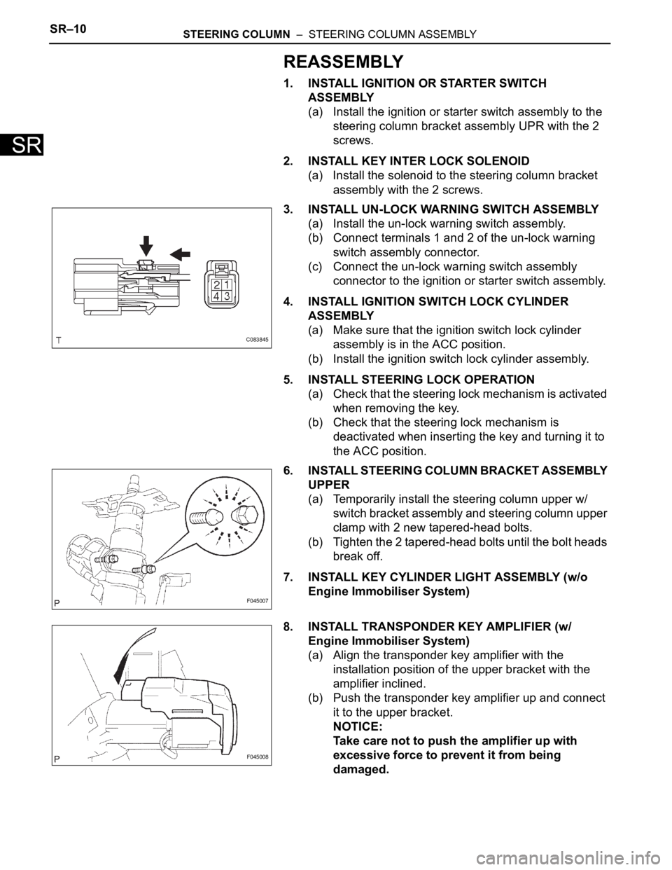
REASSEMBLY
1. INSTALL IGNITION OR STARTER SWITCH
ASSEMBLY
(a) Install the ignition or starter switch assembly to the
steering column bracket assembly UPR with the 2
screws.
2. INSTALL KEY INTER LOCK SOLENOID
(a) Install the solenoid to the steering column bracket
assembly with the 2 screws.
3. INSTALL UN-LOCK WARNING SWITCH ASSEMBLY
(a) Install the un-lock warning switch assembly.
(b) Connect terminals 1 and 2 of the un-lock warning
switch assembly connector.
(c) Connect the un-lock warning switch assembly
connector to the ignition or starter switch assembly.
4. INSTALL IGNITION SWITCH LOCK CYLINDER
ASSEMBLY
(a) Make sure that the ignition switch lock cylinder
assembly is in the ACC position.
(b) Install the ignition switch lock cylinder assembly.
5. INSTALL STEERING LOCK OPERATION
(a) Check that the steering lock mechanism is activated
when removing the key.
(b) Check that the steering lock mechanism is
deactivated when inserting the key and turning it to
the ACC position.
6. INSTALL STEERING COLUMN BRACKET ASSEMBLY
UPPER
(a) Temporarily install the steering column upper w/
switch bracket assembly and steering column upper
clamp with 2 new tapered-head bolts.
(b) Tighten the 2 tapered-head bolts until the bolt heads
break off.
7. INSTALL KEY CYLINDER LIGHT ASSEMBLY (w/o
Engine Immobiliser System)
8. INSTALL TRANSPONDER KEY AMPLIFIER (w/
Engine Immobiliser System)
(a) Align the transponder key amplifier with the
installation position of the upper bracket with the
amplifier inclined.
(b) Push the transponder key amplifier up and connect
it to the upper bracket.
NOTICE:
Take care not to push the amplifier up with
excessive force to prevent it from being
damaged.
C083845
F045007
F045008
Page 2681 of 3000
SR–8STEERING COLUMN – STEERING COLUMN ASSEMBLY
SR
DISASSEMBLY
1. REMOVE STEERING INTERMEDIATE SHAFT
ASSEMBLY
(a) Align the matchmarks on the steering intermediate
shaft assembly and main shaft.
(b) Remove the bolt and steering intermediate shaft
assembly.
2. REMOVE KEY CYLINDER LIGHT ASSEMBLY (w/o
Engine Immobiliser System)
3. REMOVE TRANSPONDER KEY AMPLIFIER (w/
Engine Immobiliser System)
(a) Widen the claw hanging onto the upper bracket by
approx. 1.0 mm (0.039 in.) using a screwdriver.
(b) Pull the transponder key amplifier toward the rear of
the vehicle with the claw open.
NOTICE:
Take care not to use excessive force to prevent
the case from being damaged.
4. REMOVE STEERING COLUMN BRACKET
ASSEMBLY UPPER
(a) Using a centering punch, mark the center of the 2
tapered-head bolts.
(b) Using a 3 to 4 mm (0.12 to 0.16 in.) drill, drill a hole
into the heads of the 2 bolts.
(c) Using a screw extractor, remove the 2 bolts and
steering column upper w/ switch bracket assembly.
5. REMOVE IGNITION SWITCH LOCK CYLINDER
ASSEMBLY
(a) Place the ignition switch lock cylinder assembly in
the ACC position.
(b) Push down the stop pin with a screwdriver, and pull
out the cylinder assembly.
6. REMOVE UN-LOCK WARNING SWITCH ASSEMBLY
(a) Disconnect the un-lock warning switch assembly
connector from the ignition or starter switch
assembly.
(b) Remove the un-lock warning switch assembly by
pushing up the center part and releasing the 2
claws.
F045002E01
F045003
F045004E01
F045005
F045006E01
Page 2682 of 3000
STEERING COLUMN – STEERING COLUMN ASSEMBLYSR–9
SR
(c) Disengage the secondary locking device.
(d) Using a screwdriver, disengage the locking lug of
terminals 1 and 2, and pull the terminals out from
the rear side of the un-lock warning switch
assembly.
7. REMOVE KEY INTER LOCK SOLENOID
(a) Remove the 2 screws and solenoid from the
steering column bracket assembly.
8. REMOVE IGNITION OR STARTER SWITCH
ASSEMBLY
(a) Remove the 2 screws and ignition or starter switch
assembly from the steering column bracket
assembly UPR.
C083844