2007 TOYOTA SIENNA reset
[x] Cancel search: resetPage 2264 of 3000
TW–26TIRE AND WHEEL – TIRE PRESSURE WARNING SYSTEM
TW
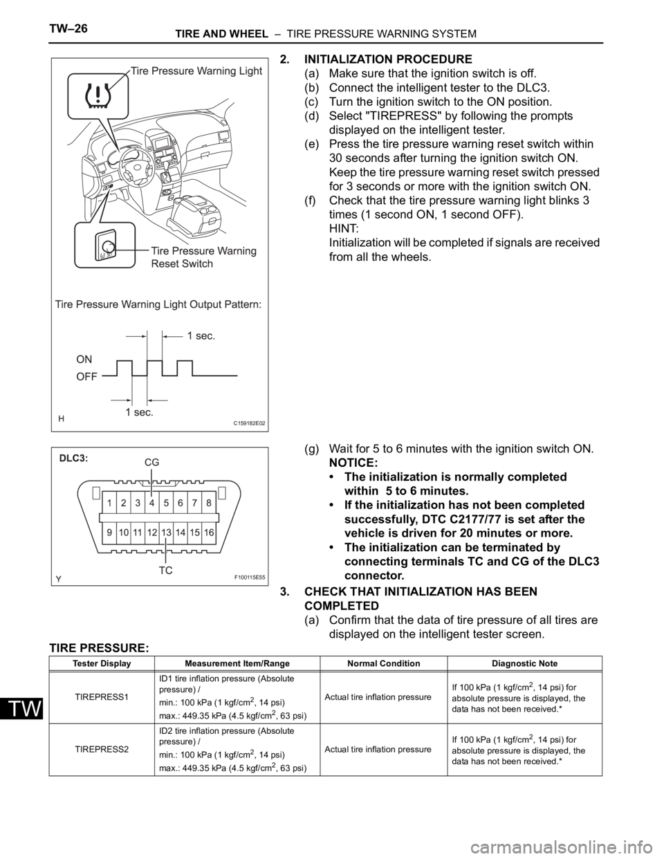
2. INITIALIZATION PROCEDURE
(a) Make sure that the ignition switch is off.
(b) Connect the intelligent tester to the DLC3.
(c) Turn the ignition switch to the ON position.
(d) Select "TIREPRESS" by following the prompts
displayed on the intelligent tester.
(e) Press the tire pressure warning reset switch within
30 seconds after turning the ignition switch ON.
Keep the tire pressure warning reset switch pressed
for 3 seconds or more with the ignition switch ON.
(f) Check that the tire pressure warning light blinks 3
times (1 second ON, 1 second OFF).
HINT:
Initialization will be completed if signals are received
from all the wheels.
(g) Wait for 5 to 6 minutes with the ignition switch ON.
NOTICE:
• The initialization is normally completed
within 5 to 6 minutes.
• If the initialization has not been completed
successfully, DTC C2177/77 is set after the
vehicle is driven for 20 minutes or more.
• The initialization can be terminated by
connecting terminals TC and CG of the DLC3
connector.
3. CHECK THAT INITIALIZATION HAS BEEN
COMPLETED
(a) Confirm that the data of tire pressure of all tires are
displayed on the intelligent tester screen.
TIRE PRESSURE:
C159182E02
F100115E55
Tester Display Measurement Item/Range Normal Condition Diagnostic Note
TIREPRESS1ID1 tire inflation pressure (Absolute
pressure) /
min.: 100 kPa (1 kgf/cm
2, 14 psi)
max.: 449.35 kPa (4.5 kgf/cm2, 63 psi)Actual tire inflation pressureIf 100 kPa (1 kgf/cm
2, 14 psi) for
absolute pressure is displayed, the
data has not been received.*
TIREPRESS2ID2 tire inflation pressure (Absolute
pressure) /
min.: 100 kPa (1 kgf/cm
2, 14 psi)
max.: 449.35 kPa (4.5 kgf/cm2, 63 psi)Actual tire inflation pressureIf 100 kPa (1 kgf/cm
2, 14 psi) for
absolute pressure is displayed, the
data has not been received.*
Page 2272 of 3000
TW–22TIRE AND WHEEL – TIRE PRESSURE WARNING SYSTEM
TW
NOTICE:
• The transmitter ID is written on the tire
pressure warning valve and
transmitter. It will be unable to be read
after installing the tire pressure
warning valve and transmitter on the
tire and wheel. Therefore, take a note
of the transmitter ID before installing
the tire pressure warning valve and
transmitter.
• The ID registration must be performed
for all tire pressure warning valve and
transmitters. Check the DATA LIST,
replace the exchanged ID with a new
ID, and make a new data list of all 4
tires for the vehicle.
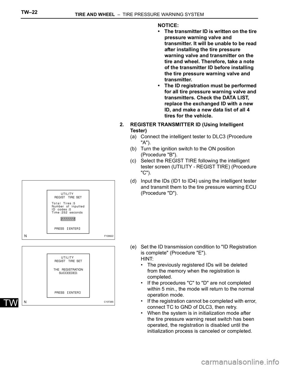
2. REGISTER TRANSMITTER ID (Using Intelligent
Te s t e r )
(a) Connect the intelligent tester to DLC3 (Procedure
"A").
(b) Turn the ignition switch to the ON position
(Procedure "B").
(c) Select the REGIST TIRE following the intelligent
tester screen (UTILITY - REGIST TIRE) (Procedure
"C").
(d) Input the IDs (ID1 to ID4) using the intelligent tester
and transmit them to the tire pressure warning ECU
(Procedure "D").
(e) Set the ID transmission condition to "ID Registration
is complete" (Procedure "E").
HINT:
• The previously registered IDs will be deleted
from the memory when the registration is
completed.
• If the procedures "C" to "D" are not completed
within 5 min., the mode will return to the normal
operation mode.
• If the registration cannot be completed with error,
connect TC to GND of DLC3, then retry.
• When the system is in initialization mode after
the tire pressure warning reset switch has been
operated, the registration is disabled until the
initialization process is canceled or completed.
F100622
C107265
Page 2275 of 3000
TW–28TIRE AND WHEEL – TIRE PRESSURE WARNING SYSTEM
TW
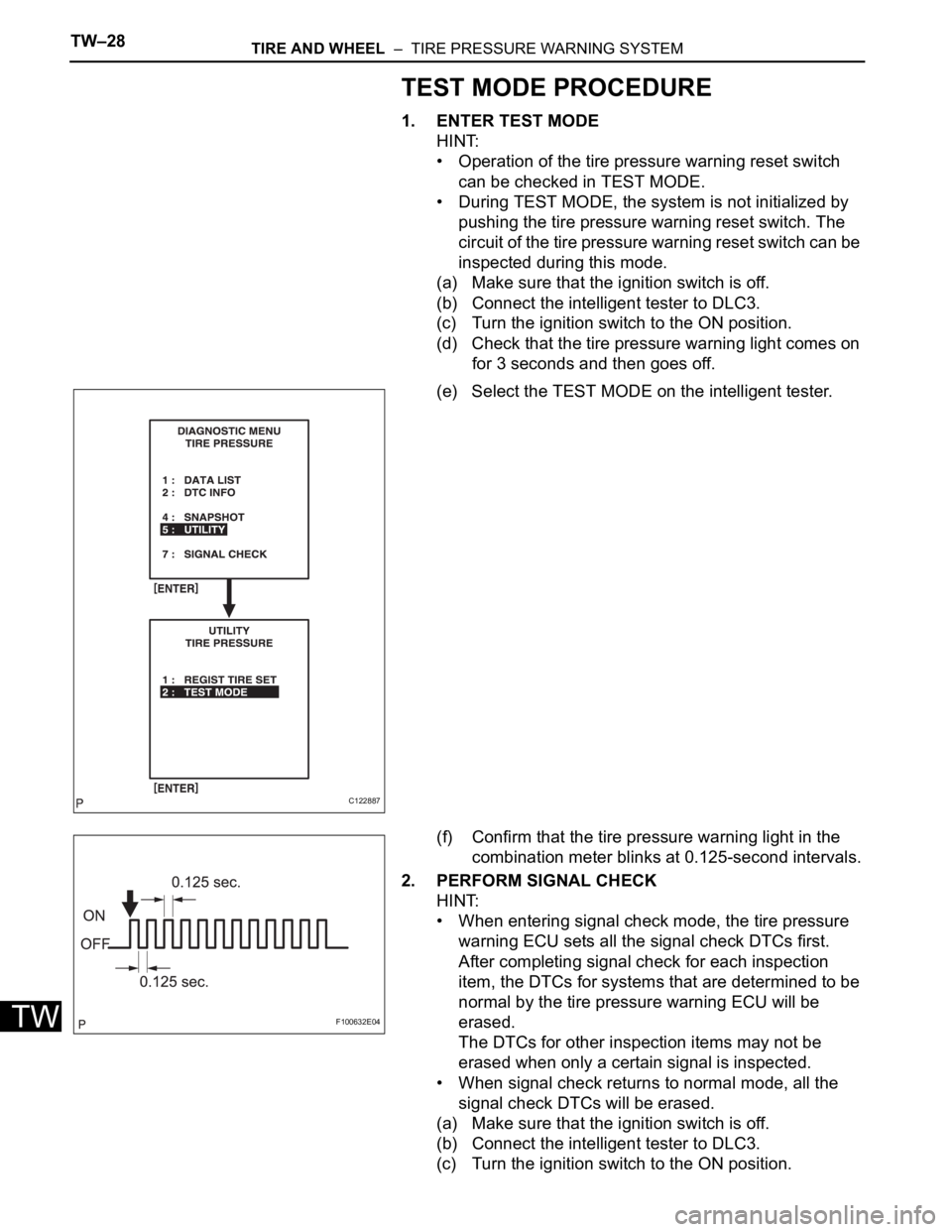
TEST MODE PROCEDURE
1. ENTER TEST MODE
HINT:
• Operation of the tire pressure warning reset switch
can be checked in TEST MODE.
• During TEST MODE, the system is not initialized by
pushing the tire pressure warning reset switch. The
circuit of the tire pressure warning reset switch can be
inspected during this mode.
(a) Make sure that the ignition switch is off.
(b) Connect the intelligent tester to DLC3.
(c) Turn the ignition switch to the ON position.
(d) Check that the tire pressure warning light comes on
for 3 seconds and then goes off.
(e) Select the TEST MODE on the intelligent tester.
(f) Confirm that the tire pressure warning light in the
combination meter blinks at 0.125-second intervals.
2. PERFORM SIGNAL CHECK
HINT:
• When entering signal check mode, the tire pressure
warning ECU sets all the signal check DTCs first.
After completing signal check for each inspection
item, the DTCs for systems that are determined to be
normal by the tire pressure warning ECU will be
erased.
The DTCs for other inspection items may not be
erased when only a certain signal is inspected.
• When signal check returns to normal mode, all the
signal check DTCs will be erased.
(a) Make sure that the ignition switch is off.
(b) Connect the intelligent tester to DLC3.
(c) Turn the ignition switch to the ON position.
C122887
F100632E04
Page 2276 of 3000
TIRE AND WHEEL – TIRE PRESSURE WARNING SYSTEMTW–29
TW
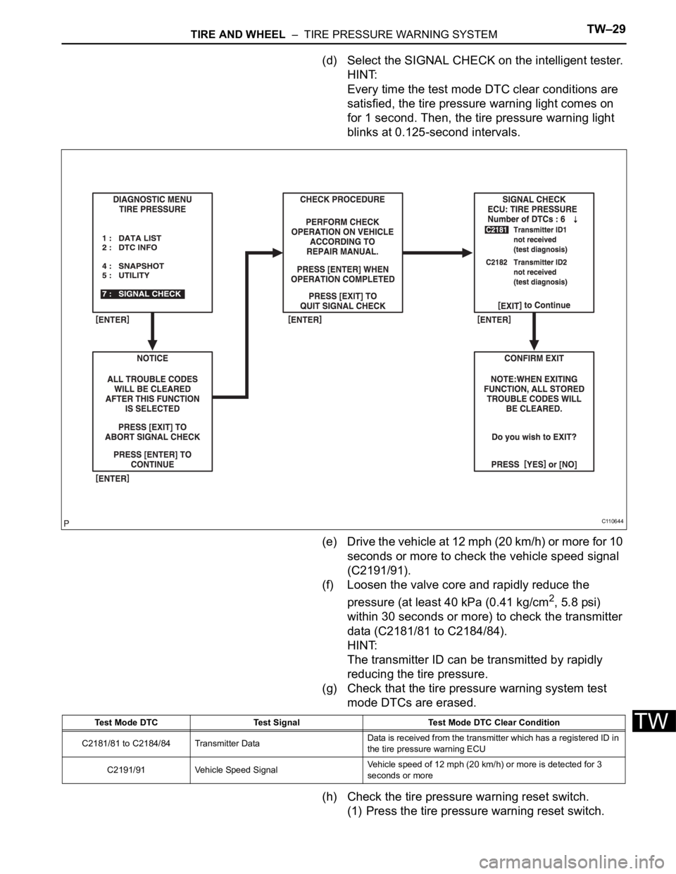
(d) Select the SIGNAL CHECK on the intelligent tester.
HINT:
Every time the test mode DTC clear conditions are
satisfied, the tire pressure warning light comes on
for 1 second. Then, the tire pressure warning light
blinks at 0.125-second intervals.
(e) Drive the vehicle at 12 mph (20 km/h) or more for 10
seconds or more to check the vehicle speed signal
(C2191/91).
(f) Loosen the valve core and rapidly reduce the
pressure (at least 40 kPa (0.41 kg/cm
2, 5.8 psi)
within 30 seconds or more) to check the transmitter
data (C2181/81 to C2184/84).
HINT:
The transmitter ID can be transmitted by rapidly
reducing the tire pressure.
(g) Check that the tire pressure warning system test
mode DTCs are erased.
(h) Check the tire pressure warning reset switch.
(1) Press the tire pressure warning reset switch.
C110644
Test Mode DTC Test Signal Test Mode DTC Clear Condition
C2181/81 to C2184/84 Transmitter DataData is received from the transmitter which has a registered ID in
the tire pressure warning ECU
C2191/91 Vehicle Speed SignalVehicle speed of 12 mph (20 km/h) or more is detected for 3
seconds or more
Page 2277 of 3000

TW–30TIRE AND WHEEL – TIRE PRESSURE WARNING SYSTEM
TW
(2) Check the tire pressure warning indicator light.
(i) Result
HINT:
After the signal check is completed, check for a
signal check DTC to confirm the system status.
(j) End of SIGNAL CHECK
After completing the test mode (SIGNAL CHECK),
turn the ignition switch off and disconnect the tester.
DTC of SIGNAL CHECK (TEST DIAGNOSIS)
function:
If a trouble code is displayed during the test mode
DTC check, check the circuit listed for that code. For
details of each code, refer to the relevant page listed
under respective "DTC No." in the chart.
Test Signal Normal Condition
Tire Pressure Warning Reset Switch• Switch ON: TPWS indicator comes on
• Switch OFF: TPWS indicator blinks at 0.125
Condition Procedure
SIGNAL CHECK DTC is output Repair the faulty part and enter SIGNAL CHECK again
SIGNAL CHECK DTCs are cleared No problem
DTC No. Detection Item Trouble Area See procedure
C2181/81 Transmitter ID1 not received• Tire pressure warning valve and transmitter
• Tire pressure warning antenna and receiver
• Wire harness or connector
• Tire pressure warning ECUTW-42
C2182/82 Transmitter ID2 not received• Tire pressure warning valve and transmitter
• Tire pressure warning antenna and receiver
• Wire harness or connector
• Tire pressure warning ECUTW-42
C2183/83 Transmitter ID3 not received• Tire pressure warning valve and transmitter
• Tire pressure warning antenna and receiver
• Wire harness or connector
• Tire pressure warning ECUTW-42
C2184/84 Transmitter ID4 not received• Tire pressure warning valve and transmitter
• Tire pressure warning antenna and receiver
• Wire harness or connector
• Tire pressure warning ECUTW-42
C2191/91 Vehicle speed signal error• Vehicle speed sensor
• Combination meter assembly
• Wire harness or connector
• Tire pressure warning ECUTW-70
Page 2278 of 3000

TIRE AND WHEEL – TIRE PRESSURE WARNING SYSTEMTW–31
TW
PROBLEM SYMPTOMS TABLE
HINT:
• Use the table below to help determine the cause of the
problem symptom. The potential causes of the symptoms
are listed in order of probability in the "Suspected Area"
column of the table. Check each symptom by checking the
suspected areas in the order they are listed. Replace parts
as necessary.
• Inspect the fuses and relays related to this system before
inspecting the suspected areas below.
TIRE PRESSURE WARNING SYSTEM:
Symptom Suspected Area See page
Tire pressure warning light does not illuminate, despite
tire pressure decreasingInitializationTW-23
Check DATA LIST (Tire inflation pressure)TW-35
ID code check (Registration)TW-20
Tire pressure warning light illuminated (Goes off during
initial check)ECU power source circuitTW-77
Tire pressure warning light circuitTW-74
Tire pressure warning light illuminated (Comes on
during initial check)Check DATA LIST (Tire inflation pressure)TW-35
Tire pressure warning light circuitTW-74
ID code check (Registration)TW-20
Initialization cannot be done Tire pressure reset switch circuitTW-72
DTC check cannot be doneECU power source circuitTW-77
TC and CG terminal circuitTW-79
Page 2279 of 3000
TW–32TIRE AND WHEEL – TIRE PRESSURE WARNING SYSTEM
TW
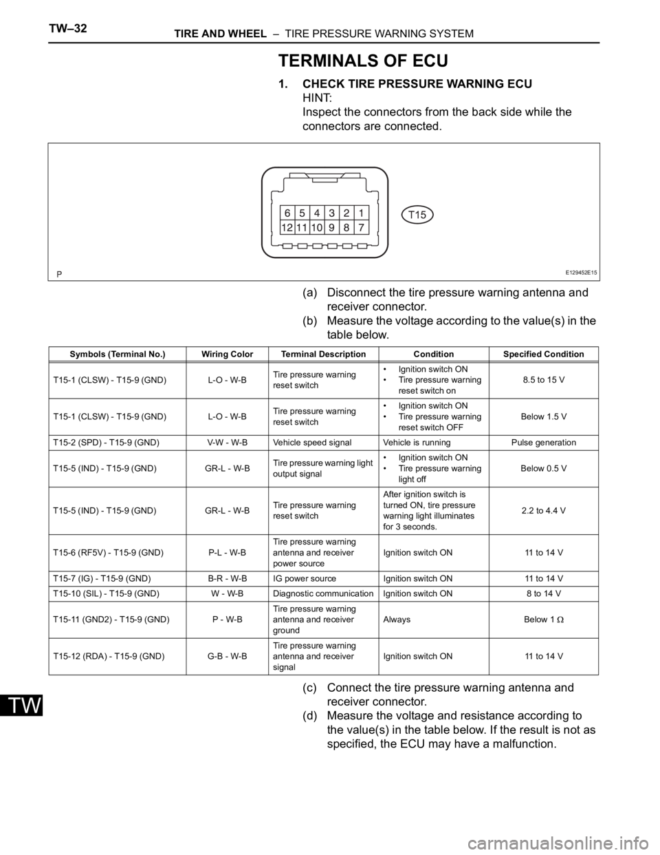
TERMINALS OF ECU
1. CHECK TIRE PRESSURE WARNING ECU
HINT:
Inspect the connectors from the back side while the
connectors are connected.
(a) Disconnect the tire pressure warning antenna and
receiver connector.
(b) Measure the voltage according to the value(s) in the
table below.
(c) Connect the tire pressure warning antenna and
receiver connector.
(d) Measure the voltage and resistance according to
the value(s) in the table below. If the result is not as
specified, the ECU may have a malfunction.
E129452E15
Symbols (Terminal No.) Wiring Color Terminal Description ConditionSpecified Condition
T15-1 (CLSW) - T15-9 (GND) L-O - W-BTire pressure warning
reset switch• Ignition switch ON
• Tire pressure warning
reset switch on8.5 to 15 V
T15-1 (CLSW) - T15-9 (GND) L-O - W-BTire pressure warning
reset switch• Ignition switch ON
• Tire pressure warning
reset switch OFFBelow 1.5 V
T15-2 (SPD) - T15-9 (GND) V-W - W-B Vehicle speed signal Vehicle is running Pulse generation
T15-5 (IND) - T15-9 (GND) GR-L - W-BTire pressure warning light
output signal• Ignition switch ON
• Tire pressure warning
light offBelow 0.5 V
T15-5 (IND) - T15-9 (GND) GR-L - W-BTire pressure warning
reset switchAfter ignition switch is
turned ON, tire pressure
warning light illuminates
for 3 seconds.2.2 to 4.4 V
T15-6 (RF5V) - T15-9 (GND) P-L - W-BTire pressure warning
antenna and receiver
power sourceIgnition switch ON 11 to 14 V
T15-7 (IG) - T15-9 (GND) B-R - W-B IG power source Ignition switch ON 11 to 14 V
T15-10 (SIL) - T15-9 (GND) W - W-B Diagnostic communication Ignition switch ON 8 to 14 V
T15-11 (GND2) - T15-9 (GND) P - W-BTire pressure warning
antenna and receiver
groundAlways Below 1
T15-12 (RDA) - T15-9 (GND) G-B - W-BTire pressure warning
antenna and receiver
signalIgnition switch ON 11 to 14 V
Page 2282 of 3000

TW–38TIRE AND WHEEL – TIRE PRESSURE WARNING SYSTEM
TW
DATA LIST / ACTIVE TEST
1. DATA LIST
HINT:
Using the intelligent tester to read the DATA LIST allows
the values or states of switches, sensor, actuators and
other items to be read without removing any parts. This
non-intrusive inspection can be very useful because
intermittent conditions or signals may be discovered
before parts or wiring is disturbed. Reading the DATA
LIST information early in troubleshooting is one way to
save diagnostic time.
NOTICE:
In the table below, the values listed under "Normal
Condition" are reference values. Do not depend
solely on these reference values when deciding
whether a part is faulty or not.
(a) Make sure that the ignition switch is off.
(b) Connect the intelligent tester to DLC3.
(c) Turn the ignition switch to the ON position.
(d) Following the display on the intelligent tester, read
"DATA LIST".
Tester Display Measurement Item/Range Normal Condition Diagnostic Note
MODE STATUSTire pressure warning system mode/NORMAL
or REG 2nd or REG M or TESTNORMAL: Normal mode
TEST: Test mode-
MAIN TIRENumber of main tire ID to be registered/0, 1, 2,
3, 40 to 4 should be displayed -
VEHICLE SPDVehicle speed reading/min.: 0 km/h (0 mph),
max.: 255 km/h (158 mph)Actual vehicle speedSpeed indicated on the
combination meter
REGIT ID1 CODE
Registered ID1 code/min.: 0, max.: FFFFFFF
*1The ID No. registered in the
transmitter ID1 is displayed-
REGIT ID2 CODE
Registered ID2 code/min.: 0, max.: FFFFFFF
*1The ID No. registered in the
transmitter ID2 is displayed-
REGIT ID3 CODE
Registered ID3 code/min.: 0, max.: FFFFFFF
*1The ID No. registered in the
transmitter ID3 is displayed-
REGIT ID4 CODE
Registered ID4 code/min.: 0, max.: FFFFFFF
*1The ID No. registered in the
transmitter ID4 is displayed-
TRANS STATUS ID code transmission status/FINISH or NOW FINISH or NOW -
INITIAL SW Tire pressure warning reset switch/ON, OFFON: Switch on
OFF: Switch off-
TIREPRESS1ID1 tire inflation pressure (Absolute pressure) /
min.: 100 kPa (1 kgf/cm
2, 14 psi)
max.: 449.35 kPa (4.5 kgf/cm2, 63 psi)Actual tire inflation pressureIf 100 kPa (1 kgf/cm
2, 14 psi)
for absolute pressure is
displayed, the data has not
been received.
*2
TIREPRESS2ID2 tire inflation pressure (Absolute pressure) /
min.: 100 kPa (1 kgf/cm2, 14 psi)
max.: 449.35 kPa (4.5 kgf/cm2, 63 psi)Actual tire inflation pressureIf 100 kPa (1 kgf/cm
2, 14 psi)
for absolute pressure is
displayed, the data has not
been received.
*2
TIREPRESS3ID3 tire inflation pressure (Absolute pressure) /
min.: 100 kPa (1 kgf/cm2, 14 psi)
max.: 449.35 kPa (4.5 kgf/cm2, 63 psi)Actual tire inflation pressureIf 100 kPa (1 kgf/cm
2, 14 psi)
for absolute pressure is
displayed, the data has not
been received.
*2
TIREPRESS4ID4 tire inflation pressure (Absolute pressure) /
min.: 100 kPa (1 kgf/cm2, 14 psi)
max.: 449.35 kPa (4.5 kgf/cm2, 63 psi)Actual tire inflation pressureIf 100 kPa (1 kgf/cm
2, 14 psi)
for absolute pressure is
displayed, the data has not
been received.
*2