Page 1701 of 3000

AX–18U151F AUTOMATIC TRANSAXLE – AUTOMATIC TRANSAXLE SYSTEM
AX
INITIALIZATION
1. RESET MEMORY
NOTICE:
• Perform the RESET MEMORY (AT initialization)
when replacing the automatic transaxle assembly,
engine assembly or ECM.
• The RESET MEMORY can be performed only with
the Intelligent tester.
HINT:
The ECM memorizes the condition that the ECT controls
the automatic transaxle assembly and engine assembly
according to those characteristics. Therefore, when the
automatic transaxle assembly, engine assembly, or ECM
has been replaced, it is necessary to reset the memory
so that the ECM can memorize the new information.
Reset procedure is as follows.
(a) Turn the engine switch off.
(b) Connect the intelligent tester together with the CAN
VIM (controller area network vehicle interface
module) to the DLC3.
(c) Turn the ignition switch to the ON position and push
the intelligent tester main switch on.
(d) Select the item "DIAGNOSIS / ENHANCED OBD
II".
(e) Perform the reset memory procedure from the
ENGINE menu.
CAUTION:
After performing the RESET MEMORY, be sure
to perform the ROAD TEST (See page AX-9)
described earlier.
HINT:
The ECM is learned by performing the ROAD TEST.
(1) Tester menu flow:
Page 1814 of 3000

AX–18U151F AUTOMATIC TRANSAXLE – AUTOMATIC TRANSAXLE SYSTEM
AX
INITIALIZATION
1. RESET MEMORY
NOTICE:
• Perform the RESET MEMORY (AT initialization)
when replacing the automatic transaxle assembly,
engine assembly or ECM.
• The RESET MEMORY can be performed only with
the Intelligent tester.
HINT:
The ECM memorizes the condition that the ECT controls
the automatic transaxle assembly and engine assembly
according to those characteristics. Therefore, when the
automatic transaxle assembly, engine assembly, or ECM
has been replaced, it is necessary to reset the memory
so that the ECM can memorize the new information.
Reset procedure is as follows.
(a) Turn the engine switch off.
(b) Connect the intelligent tester together with the CAN
VIM (controller area network vehicle interface
module) to the DLC3.
(c) Turn the ignition switch to the ON position and push
the intelligent tester main switch on.
(d) Select the item "DIAGNOSIS / ENHANCED OBD
II".
(e) Perform the reset memory procedure from the
ENGINE menu.
CAUTION:
After performing the RESET MEMORY, be sure
to perform the ROAD TEST (See page AX-9)
described earlier.
HINT:
The ECM is learned by performing the ROAD TEST.
(1) Tester menu flow:
Page 1819 of 3000
U151F AUTOMATIC TRANSAXLE – TRANSMISSION WIREAX–133
AX
(c) Using a new gasket, install the oil pan to the
transaxle case with the 18 bolts.
Torque: 7.8 N*m (80 kgf*cm, 69 in.*lbf)
NOTICE:
Apply seal packing to the bolts and tighten them
within 10 minutes of application.
4. CONNECT CABLE TO NEGATIVE BATTERY
TERMINAL
5. ADD AUTOMATIC TRANSAXLE FLUID
6. INSPECT AUTOMATIC TRANSAXLE FLUID (See page
AX-123)
7. INSTALL ENGINE UNDER COVER NO.1
8. RESET MEMORY
HINT:
(See page AX-16)
C091925
Page 1827 of 3000

U151F AUTOMATIC TRANSAXLE – VALVE BODY ASSEMBLYAX–141
AX
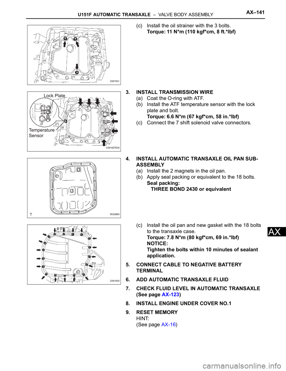
(c) Install the oil strainer with the 3 bolts.
Torque: 11 N*m (110 kgf*cm, 8 ft.*lbf)
3. INSTALL TRANSMISSION WIRE
(a) Coat the O-ring with ATF.
(b) Install the ATF temperature sensor with the lock
plate and bolt.
Torque: 6.6 N*m (67 kgf*cm, 58 in.*lbf)
(c) Connect the 7 shift solenoid valve connectors.
4. INSTALL AUTOMATIC TRANSAXLE OIL PAN SUB-
ASSEMBLY
(a) Install the 2 magnets in the oil pan.
(b) Apply seal packing or equivalent to the 18 bolts.
Seal packing:
THREE BOND 2430 or equivalent
(c) Install the oil pan and new gasket with the 18 bolts
to the transaxle case.
Torque: 7.8 N*m (80 kgf*cm, 69 in.*lbf)
NOTICE:
Tighten the bolts within 10 minutes of sealant
application.
5. CONNECT CABLE TO NEGATIVE BATTERY
TERMINAL
6. ADD AUTOMATIC TRANSAXLE FLUID
7. CHECK FLUID LEVEL IN AUTOMATIC TRANSAXLE
(See page AX-123)
8. INSTALL ENGINE UNDER COVER NO.1
9. RESET MEMORY
HINT:
(See page AX-16)
C091931
C091927E04
D030865
C091925
Page 1887 of 3000

U151F AUTOMATIC TRANSAXLE – AUTOMATIC TRANSAXLE ASSEMBLYAX–171
AX
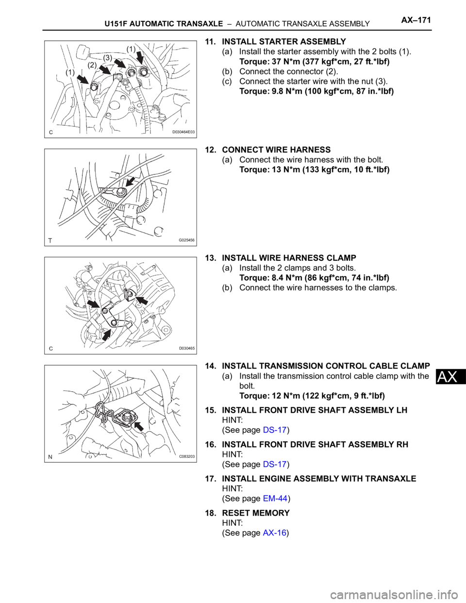
11. INSTALL STARTER ASSEMBLY
(a) Install the starter assembly with the 2 bolts (1).
Torque: 37 N*m (377 kgf*cm, 27 ft.*lbf)
(b) Connect the connector (2).
(c) Connect the starter wire with the nut (3).
Torque: 9.8 N*m (100 kgf*cm, 87 in.*lbf)
12. CONNECT WIRE HARNESS
(a) Connect the wire harness with the bolt.
Torque: 13 N*m (133 kgf*cm, 10 ft.*lbf)
13. INSTALL WIRE HARNESS CLAMP
(a) Install the 2 clamps and 3 bolts.
Torque: 8.4 N*m (86 kgf*cm, 74 in.*lbf)
(b) Connect the wire harnesses to the clamps.
14. INSTALL TRANSMISSION CONTROL CABLE CLAMP
(a) Install the transmission control cable clamp with the
bolt.
Torque: 12 N*m (122 kgf*cm, 9 ft.*lbf)
15. INSTALL FRONT DRIVE SHAFT ASSEMBLY LH
HINT:
(See page DS-17)
16. INSTALL FRONT DRIVE SHAFT ASSEMBLY RH
HINT:
(See page DS-17)
17. INSTALL ENGINE ASSEMBLY WITH TRANSAXLE
HINT:
(See page EM-44)
18. RESET MEMORY
HINT:
(See page AX-16)
D030464E03
G025456
D030465
C083203
Page 2251 of 3000

TW–16TIRE AND WHEEL – TIRE PRESSURE WARNING SYSTEM
TW
SYSTEM DESCRIPTION
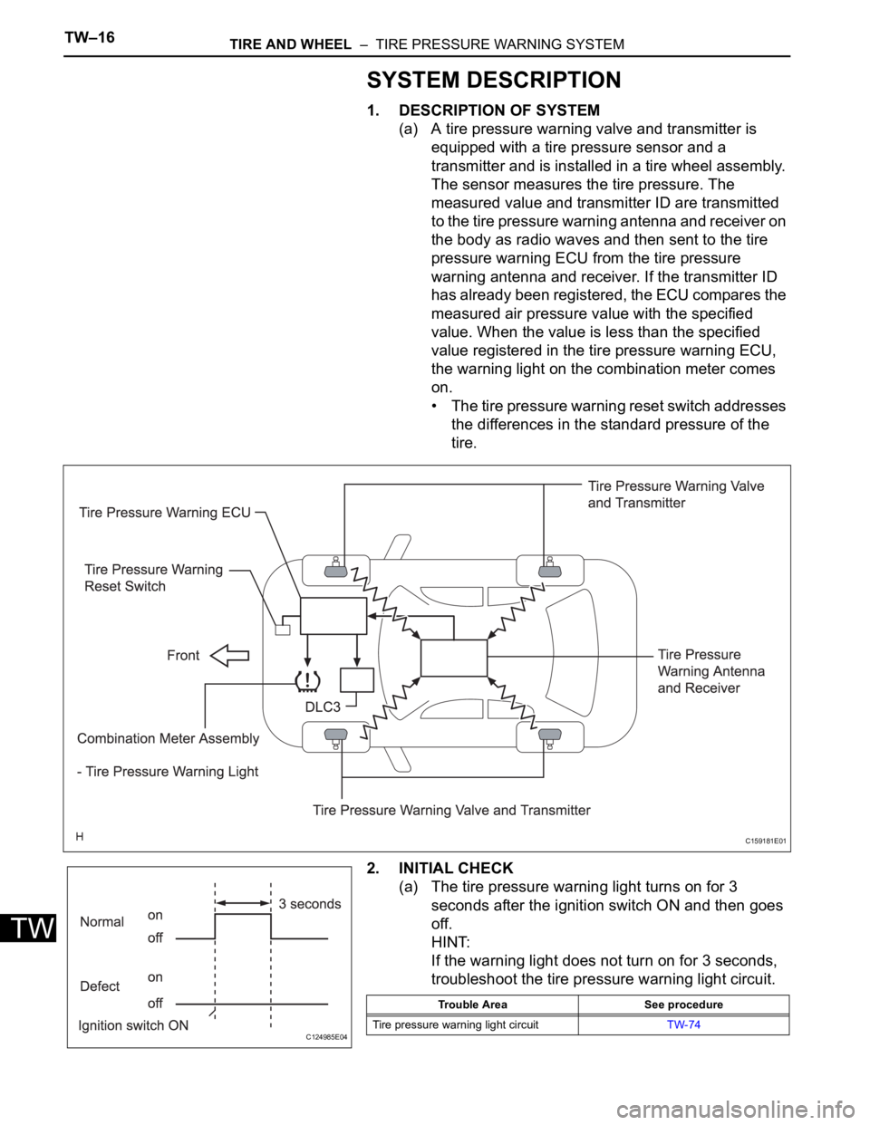
1. DESCRIPTION OF SYSTEM
(a) A tire pressure warning valve and transmitter is
equipped with a tire pressure sensor and a
transmitter and is installed in a tire wheel assembly.
The sensor measures the tire pressure. The
measured value and transmitter ID are transmitted
to the tire pressure warning antenna and receiver on
the body as radio waves and then sent to the tire
pressure warning ECU from the tire pressure
warning antenna and receiver. If the transmitter ID
has already been registered, the ECU compares the
measured air pressure value with the specified
value. When the value is less than the specified
value registered in the tire pressure warning ECU,
the warning light on the combination meter comes
on.
• The tire pressure warning reset switch addresses
the differences in the standard pressure of the
tire.
2. INITIAL CHECK
(a) The tire pressure warning light turns on for 3
seconds after the ignition switch ON and then goes
off.
HINT:
If the warning light does not turn on for 3 seconds,
troubleshoot the tire pressure warning light circuit.
C159181E01
C124985E04
Trouble Area See procedure
Tire pressure warning light circuitTW-74
Page 2252 of 3000

TIRE AND WHEEL – TIRE PRESSURE WARNING SYSTEMTW–17
TW
3. WHEN TIRE PRESSURE WARNING LIGHT IS LIT
(a) When the tire pressure warning light does not go off,
or when it comes on during driving, check tire
pressure. If the tire pressure warning light comes on
within several hours after adjusting the tire
pressure, the tire may have a slow air leak.
(b) Under the following conditions, the system may not
function properly.
• Facilities or devices that use similar radio
frequencies are located in the vicinity of the
vehicle.
• A radio device of similar frequency is used in the
vehicle.
• A large amount of snow or ice is stuck to the
vehicle, especially onto the wheels and around
the wheel houses.
• The ID of the tire pressure warning valve and
transmitter has not been registered with the
ECU.
• A film or window tint that may interfere with radio
waves is attached on the glass.
• The battery of the sensor has been depleted.
• The tires without tire pressure warning valve and
transmitter are used.
• Tire chains are used.
• The use of non-genuine wheels may result in the
system failure or air-leak.
• Depending on the tire type, the system may not
function properly even though the specified
wheels are used.
(c) After removing and installing the ECU or a sensor,
check for a diagnostic trouble code and verify that it
is a normal code.
4. FUNCTION OF COMPONENTS
5. TIRE PRESSURE WARNING RESET SWITCH
• By operating the tire pressure warning reset switch,
the tire pressure warning ECU can be set to issue a
warning at an inflation pressure that corresponds to
the standard pressure of tires.
Therefore, the dealer must set the warning threshold
to the proper value in order to comply with the local
regulations.
Components Function
Tire pressure warning valve and transmitterCombined as a single unit with a disc wheel air valve, it measures tire pressure and
temperature and transmits an ID number for measurement value and identification.
Built-in the battery.
Tire pressure warning antenna and receiverReceives and transmits a necessary signal from the transmitter to the tire pressure
warning ECU.
Tire pressure warning ECUReceives a signal from the receiver and identifies it as vehicle's own signal. If the
measured value is equal to or lower than the specified value, it transmits a signal so
that the tire pressure warning light on the combination meter comes on.
Tire pressure warning lightLocated in the combination meter, it informs the driver of lowered tire air pressure
and system failure.
Tire pressure warning reset switch Enters the initialization mode for the change of the standard pressure
Page 2253 of 3000
TW–18TIRE AND WHEEL – TIRE PRESSURE WARNING SYSTEM
TW
• Operate the tire pressure warning reset switch only
after the inflation pressures of all tires have been
adjusted on the vehicle.
• To initialize the system, press and hold the tire
pressure warning reset switch for 3 seconds or longer
with the ignition switch ON. After the initialization
process has started, the warning light blinks 3 times
(1 second on, 1 second off).
• During initialization, the tire pressure warning valve
and transmitter measures the inflation pressure of the
tires, and registers the signals that are transmitted
into the tire pressure warning ECU at a frequency of
once per 3 minutes. The initialization process is
completed when signals from all the tires have been
received. It takes several minutes.