2007 TOYOTA SIENNA reset
[x] Cancel search: resetPage 96 of 3000

U151E AUTOMATIC TRANSAXLE – AUTOMATIC TRANSAXLE ASSEMBLYAX–169
AX
11. INSTALL WIRE HARNESS CLAMP
(a) Install the 2 clamps and 3 bolts.
Torque: 8.4 N*m (86 kgf*cm, 74 in.*lbf)
(b) Connect the wire harnesses to the clamps.
12. INSTALL TRANSMISSION CONTROL CABLE CLAMP
(a) Install the transmission control cable clamp with the
bolt.
Torque: 12 N*m (122 kgf*cm, 9 ft.*lbf)
13. INSTALL FRONT DRIVE SHAFT ASSEMBLY LH
HINT:
(See page DS-17)
14. INSTALL FRONT DRIVE SHAFT ASSEMBLY RH
HINT:
(See page DS-17)
15. INSTALL ENGINE ASSEMBLY WITH TRANSAXLE
HINT:
(See page EM-44)
16. RESET MEMORY
HINT:
(See page AX-16)
D030465
C083203
Page 106 of 3000

U151F AUTOMATIC TRANSAXLE – AUTOMATIC TRANSAXLE ASSEMBLYAX–171
AX
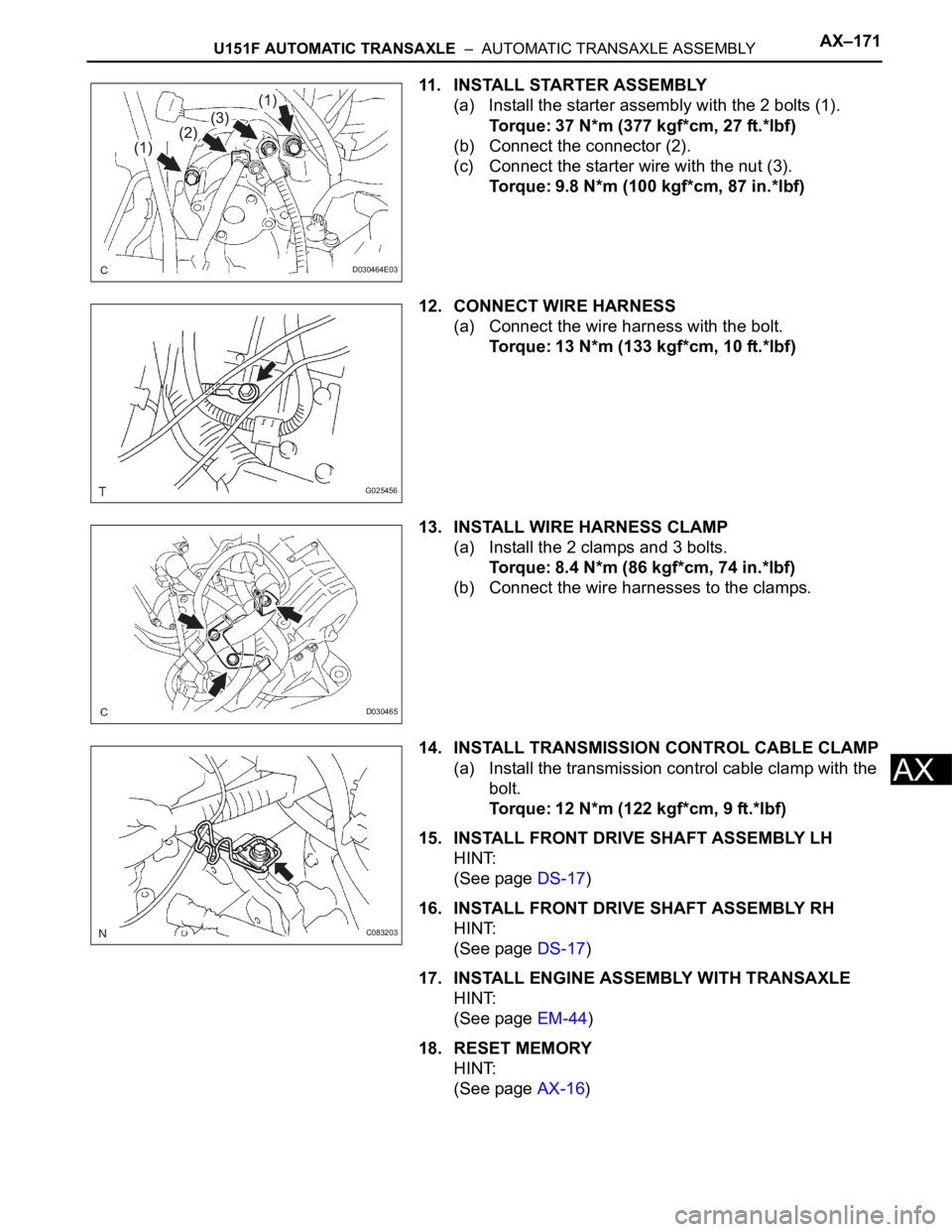
11. INSTALL STARTER ASSEMBLY
(a) Install the starter assembly with the 2 bolts (1).
Torque: 37 N*m (377 kgf*cm, 27 ft.*lbf)
(b) Connect the connector (2).
(c) Connect the starter wire with the nut (3).
Torque: 9.8 N*m (100 kgf*cm, 87 in.*lbf)
12. CONNECT WIRE HARNESS
(a) Connect the wire harness with the bolt.
Torque: 13 N*m (133 kgf*cm, 10 ft.*lbf)
13. INSTALL WIRE HARNESS CLAMP
(a) Install the 2 clamps and 3 bolts.
Torque: 8.4 N*m (86 kgf*cm, 74 in.*lbf)
(b) Connect the wire harnesses to the clamps.
14. INSTALL TRANSMISSION CONTROL CABLE CLAMP
(a) Install the transmission control cable clamp with the
bolt.
Torque: 12 N*m (122 kgf*cm, 9 ft.*lbf)
15. INSTALL FRONT DRIVE SHAFT ASSEMBLY LH
HINT:
(See page DS-17)
16. INSTALL FRONT DRIVE SHAFT ASSEMBLY RH
HINT:
(See page DS-17)
17. INSTALL ENGINE ASSEMBLY WITH TRANSAXLE
HINT:
(See page EM-44)
18. RESET MEMORY
HINT:
(See page AX-16)
D030464E03
G025456
D030465
C083203
Page 282 of 3000

WINDSHIELD / WINDOWGLASS – POWER WINDOW CONTROL SYSTEM (w/ Jam Protec-
tion Function)WS–7
WS
INITIALIZATION
NOTICE:
• Resetting the power window motor (initializing the
pulse sensor) is necessary when the battery terminal
is disconnected; when the master switch, wire
harness, power window regulator and power window
motor are replaced or removed/installed; or when the
fuses are replaced. AUTO operation function, jam
protection function and remote operation function via
the power window master switch do not operate
without resetting.
• If the AUTO switch (driver side switch) of the master
switch has been continuously operated for a long
time, the power window motor will stop so that no
additional load can be applied to the motor.
Continuing to operate the switch even after the motor
has stopped will cause the switch to blink while
restricting the AUTO UP/DOWN function and the
remote UP/DOWN function. If this happens, reset the
motor again after several minutes have passed.
• Whenever disconnecting the battery terminal, reset all
the other systems besides the power window control
system.
1. RESET POWER WINDOW REGULATOR MOTOR
(DRIVER SIDE)
(a) Turn the ignition switch ON.
(b) Halfway open the power window by pressing the
power window switch.
(c) Fully pull up the switch until the power window is
fully closed and continue to hold the switch for
approx. 1 second after the power window is fully
closed.
(d) Check that the AUTO UP/DOWN function operates
normally.
If the AUTO UP/DOWN function operates normally,
reset operations have been completed at this time.
If not normal, follow steps below.
(1) Disconnect the negative battery terminal for 10
seconds.
(2) Connect the battery terminal.
(3) Perform the above steps (a) to (d) again.
HINT:
If operation is normal, reset operations have
been completed at this time. If not normal, follow
steps (4) to (7).
(4) Turn the ignition switch ON.
(5) Halfway open the power window by pressing the
power window switch.
(6) Fully pull up the switch until the power window is
fully closed and continue to hold the switch for
approx. 12 seconds after the power window is
fully closed.
(7) Check that the AUTO UP/DOWN function
operates normally.
Page 313 of 3000

ED–6ENGINE HOOD / DOOR – POWER SLIDE DOOR SYSTEM
ED
(a) Data List / Active Test (See page ED-22).
(b) Operation check (See page ED-6).
(c) Inspection.
(d) Terminals of ECU (See page ED-17).
NEXT
NEXT
NEXT
NEXT
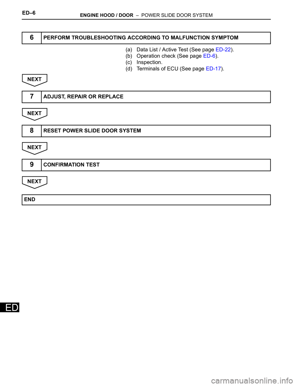
6PERFORM TROUBLESHOOTING ACCORDING TO MALFUNCTION SYMPTOM
7ADJUST, REPAIR OR REPLACE
8RESET POWER SLIDE DOOR SYSTEM
9CONFIRMATION TEST
END
Page 318 of 3000

2GR-FE ENGINE CONTROL SYSTEM – SFI SYSTEMES–1
ES
SFI SYSTEM
PRECAUTION
1. INITIALIZATION
NOTICE:
• Perform RESET MEMORY (AT initialization) when
replacing the automatic transaxle assembly, engine
assembly or ECM (See page AX-16).
• Perform REGISTRATION (VIN registration) when
replacing the ECM (See page ES-15).
HINT:
Initialization cannot be completed by only removing the
battery.
2. FOR USING INTELLIGENT TESTER
CAUTION:
Observe the following items for safety reasons:
• Before using the tester, read the instruction
manual.
• Prevent the tester cable from being caught on the
pedals, shift lever and steering wheel when
driving with the tester connected to the vehicle.
• When driving the vehicle for testing purposes
using the tester, two persons are required. One is
for driving the vehicle, and the other operates the
tester.
3. FOR USING BATTERY DURING INSPECTION
(a) While using the battery during inspection, do not
bring the positive and negative tester probes too
close to each other as a short circuit may occur.
4. COOLING FAN SYSTEM
NOTICE:
• When the ignition switch is turned off and the engine
temperature is high, the cooling fans may operate for
approximately 3 minutes.
• After turning the ignition switch off, keep hands and
objects away from the fans when they are operating.
HINT:
If all of the following are met for a certain period of time during
a few minute period immediately before the engine is
stopped, the electric fans will continue to operate for 3
minutes after the engine is stopped. This is performed to
ensure restartability and stabilize idle speed.
– The intelligent tester indicates a very high coolant
temperature.
– The intelligent tester indicates a high outside air
temperature.
– The vehicle has been driven under high load (driving on an
uphill or equivalent).
The following sensors are used for this control:
– Coolant temperature sensor
– Outside air temperature sensor
–MAF sensor
– Vehicle speed sensors
Page 352 of 3000

ES–262GR-FE ENGINE CONTROL SYSTEM – SFI SYSTEM
ES
READINESS MONITOR DRIVE
PAT T E R N
1. PURPOSE OF READINESS TESTS
• The On-Board Diagnostic (OBD II) system is
designed to monitor the performance of emission-
related components, and indicate any detected
abnormalities with DTCs (Diagnostic Trouble Codes).
Since various components need to be monitored in
different driving conditions, the OBD II system is
designed to run separate monitoring programs called
Readiness Monitors.
• The intelligent tester's software must be version 9.0 or
newer to view the Readiness Monitor status. To view
the status, select the following menu items:
DIAGNOSIS / ENHANCED OBD II / MONITOR INFO
/ MONITOR STATUS.
• When the Readiness Monitor status reads COMPL
(complete), the necessary conditions have been met
for running the performance tests for that Readiness
Monitor.
• A generic OBD II scan tool can also be used to view
the Readiness Monitor status.
HINT:
Many Inspection and Maintenance (I/M) programs
require a vehicle's Readiness Monitor status to show
COMPL before beginning emission tests.
The Readiness Monitor will be reset to INCMPL
(incomplete) if:
• The ECM has lost battery power or broken a fuse.
• DTCs have been cleared.
• The conditions for running the Readiness Monitor
have not been met.
If the Readiness Monitor status shows INCMPL, follow
the appropriate Readiness Monitor Drive Pattern to
change the status to COMPL.
CAUTION:
Strictly observe posted speed limits, traffic laws, and
road conditions when performing these drive
patterns.
NOTICE:
These drive patterns represent the fastest method of
satisfying all conditions necessary to achieve
complete status for each specific Readiness
Monitor.
In the event of a drive pattern being interrupted
(possibly due to factors such as traffic conditions),
the drive pattern can be resumed. In most cases, the
Readiness Monitor will still achieve complete status
upon completion of the drive pattern.
To ensure completion of the Readiness Monitors,
avoid sudden changes in vehicle load and speed
(driving up and down hills and/or sudden
acceleration).
Page 618 of 3000

2GR-FE ENGINE CONTROL SYSTEM – SFI SYSTEMES–325
ES
DESCRIPTION
The ECM continuously monitors its main and sub CPUs. This self-check ensures that the ECM is
functioning properly. If outputs from the CPUs are different and deviate from the standards, the ECM will
illuminate the MIL and set a DTC immediately.
The ECM also monitors the cruise control cancel circuit. If this circuit malfunctions, the ECM will set a
DTC immediately (MIL is not illuminated).
NOTICE:
First check for an exhaust gas leak around the HO2S if P0606 is present. An exhaust gas leak
generates noise in the HO2S output. The ECM may interpret this as an HO2S transistor
malfunction.
MONITOR STRATEGY
TYPICAL ENABLING CONDITIONS
TYPICAL MALFUNCTION THRESHOLDS
INSPECTION PROCEDURE
(a) Connect the intelligent tester to the DLC3.
(b) Turn the ignition switch to the ON position.
(c) Turn the tester on.
(d) Clear the DTC.
(e) Turn the ignition switch off.
(f) Disconnect the battery negative terminal and wait for 1
minute.
(g) Connect the battery negative terminal.
DTC P0607 Control Module Performance
DTC No. DTC Detection Condition Trouble Area
P0607• ECM main CPU error
• ECM sub CPU error
• Cruise control cancel circuit malfunctionECM
Related DTC P0607: ECM CPU malfunction
Required sensors/Components ECM
Frequency of Operation Continuous
Duration Within 1 second
MIL Operation Immediate
Sequence of Operation None
Monitor runs whenever the following DTCs are not present None
Either of the following conditions is met: Condition A or B
A. All of the following conditions are met: Conditions (a), (b) and (c)
(a) CPU reset 1 time or more
(b) Learned TP - learned APP 0.4 V or more
(c) Throttle actuator OFF
B. CPU reset 2 times or more
1CHECK WHETHER DTC OUTPUT RECURS (IN ADDITION TO DTC P0607)
Page 802 of 3000

ES–262GR-FE ENGINE CONTROL SYSTEM – SFI SYSTEM
ES
READINESS MONITOR DRIVE
PAT T E R N
1. PURPOSE OF READINESS TESTS
• The On-Board Diagnostic (OBD II) system is
designed to monitor the performance of emission-
related components, and indicate any detected
abnormalities with DTCs (Diagnostic Trouble Codes).
Since various components need to be monitored in
different driving conditions, the OBD II system is
designed to run separate monitoring programs called
Readiness Monitors.
• The intelligent tester's software must be version 9.0 or
newer to view the Readiness Monitor status. To view
the status, select the following menu items:
DIAGNOSIS / ENHANCED OBD II / MONITOR INFO
/ MONITOR STATUS.
• When the Readiness Monitor status reads COMPL
(complete), the necessary conditions have been met
for running the performance tests for that Readiness
Monitor.
• A generic OBD II scan tool can also be used to view
the Readiness Monitor status.
HINT:
Many Inspection and Maintenance (I/M) programs
require a vehicle's Readiness Monitor status to show
COMPL before beginning emission tests.
The Readiness Monitor will be reset to INCMPL
(incomplete) if:
• The ECM has lost battery power or broken a fuse.
• DTCs have been cleared.
• The conditions for running the Readiness Monitor
have not been met.
If the Readiness Monitor status shows INCMPL, follow
the appropriate Readiness Monitor Drive Pattern to
change the status to COMPL.
CAUTION:
Strictly observe posted speed limits, traffic laws, and
road conditions when performing these drive
patterns.
NOTICE:
These drive patterns represent the fastest method of
satisfying all conditions necessary to achieve
complete status for each specific Readiness
Monitor.
In the event of a drive pattern being interrupted
(possibly due to factors such as traffic conditions),
the drive pattern can be resumed. In most cases, the
Readiness Monitor will still achieve complete status
upon completion of the drive pattern.
To ensure completion of the Readiness Monitors,
avoid sudden changes in vehicle load and speed
(driving up and down hills and/or sudden
acceleration).