Page 2080 of 3000
DRIVE SHAFT – FRONT DRIVE SHAFTDS–5
DS
REMOVAL
1. DRAIN AUTOMATIC TRANSAXLE FLUID
(a) Remove the drain plug, gasket and drain ATF.
(b) Install a new gasket and the drain plug.
Torque: 49 N*m (500 kgf*cm, 36 ft.*lbf)
2. DRAIN TRANSFER OIL (for 4WD)
HINT:
(See page TF-8)
3. REMOVE FRONT WHEEL
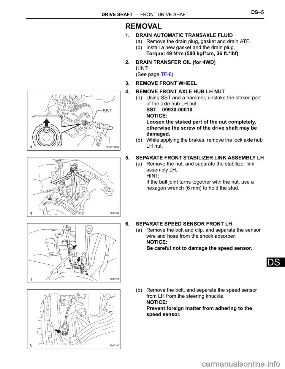
4. REMOVE FRONT AXLE HUB LH NUT
(a) Using SST and a hammer, unstake the staked part
of the axle hub LH nut.
SST 09930-00010
NOTICE:
Loosen the staked part of the nut completely,
otherwise the screw of the drive shaft may be
damaged.
(b) While applying the brakes, remove the lock axle hub
LH nut.
5. SEPARATE FRONT STABILIZER LINK ASSEMBLY LH
(a) Remove the nut, and separate the stabilizer link
assembly LH.
HINT:
If the ball joint turns together with the nut, use a
hexagon wrench (6 mm) to hold the stud.
6. SEPARATE SPEED SENSOR FRONT LH
(a) Remove the bolt and clip, and separate the sensor
wire and hose from the shock absorber.
NOTICE:
Be careful not to damage the speed sensor.
(b) Remove the bolt, and separate the speed sensor
from LH from the steering knuckle.
NOTICE:
Prevent foreign matter from adhering to the
speed sensor.
F040146E09
F040136
C083022
F040147
Page 2165 of 3000
AH–6AXLE – FRONT AXLE HUB
AH
REMOVAL
HINT:
Replace the RH side using the same procedures as for the
LH side.
1. REMOVE FRONT WHEEL
2. REMOVE FRONT AXLE HUB LH NUT (See page DS-
5)
3. SEPARATE SPEED SENSOR FRONT LH (See page
DS-5)
4. SEPARATE FRONT DISC BRAKE CALIPER
ASSEMBLY LH
(a) Remove the 2 bolts and separate the front disc
brake caliper assembly LH from the steering
knuckle LH.
NOTICE:
Use a string or other device to keep the brake
caliper from hanging down.
5. REMOVE FRONT DISC
6. SEPARATE TIE ROD END SUB-ASSEMBLY LH (See
page DS-6)
7. SEPARATE FRONT SUSPENSION ARM SUB-
ASSEMBLY LOWER NO.1 LH (See page DS-6)
8. REMOVE FRONT AXLE ASSEMBLY LH
(a) Using a plastic hammer, separate the front drive
shaft assembly LH from the front axle hub sub-
assembly LH.
NOTICE:
Be careful not to damage the boot and ABS
speed sensor rotor.
(b) Remove the 2 bolts, nuts and steering knuckle LH
with the front axle nub sub-assembly LH.
C067088
D027403
C083023
Page 2168 of 3000
AXLE – FRONT AXLE HUBAH–9
AH
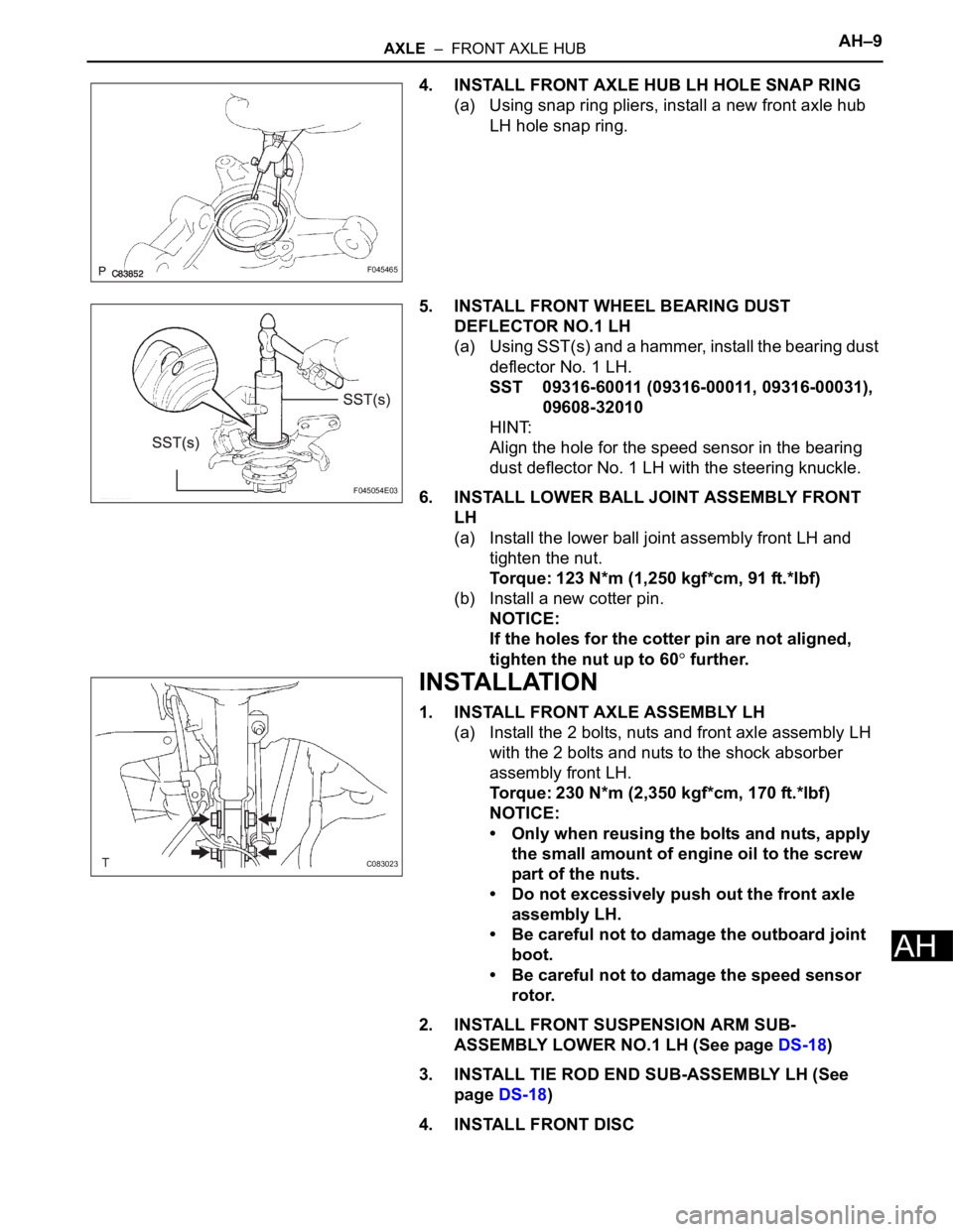
4. INSTALL FRONT AXLE HUB LH HOLE SNAP RING
(a) Using snap ring pliers, install a new front axle hub
LH hole snap ring.
5. INSTALL FRONT WHEEL BEARING DUST
DEFLECTOR NO.1 LH
(a) Using SST(s) and a hammer, install the bearing dust
deflector No. 1 LH.
SST 09316-60011 (09316-00011, 09316-00031),
09608-32010
HINT:
Align the hole for the speed sensor in the bearing
dust deflector No. 1 LH with the steering knuckle.
6. INSTALL LOWER BALL JOINT ASSEMBLY FRONT
LH
(a) Install the lower ball joint assembly front LH and
tighten the nut.
Torque: 123 N*m (1,250 kgf*cm, 91 ft.*lbf)
(b) Install a new cotter pin.
NOTICE:
If the holes for the cotter pin are not aligned,
tighten the nut up to 60
further.
INSTALLATION
1. INSTALL FRONT AXLE ASSEMBLY LH
(a) Install the 2 bolts, nuts and front axle assembly LH
with the 2 bolts and nuts to the shock absorber
assembly front LH.
Torque: 230 N*m (2,350 kgf*cm, 170 ft.*lbf)
NOTICE:
• Only when reusing the bolts and nuts, apply
the small amount of engine oil to the screw
part of the nuts.
• Do not excessively push out the front axle
assembly LH.
• Be careful not to damage the outboard joint
boot.
• Be careful not to damage the speed sensor
rotor.
2. INSTALL FRONT SUSPENSION ARM SUB-
ASSEMBLY LOWER NO.1 LH (See page DS-18)
3. INSTALL TIE ROD END SUB-ASSEMBLY LH (See
page DS-18)
4. INSTALL FRONT DISC
F045465
F045054E03
C083023
Page 2169 of 3000
AH–10AXLE – FRONT AXLE HUB
AH
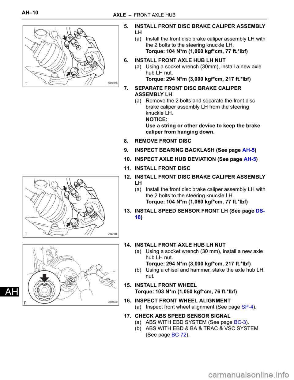
5. INSTALL FRONT DISC BRAKE CALIPER ASSEMBLY
LH
(a) Install the front disc brake caliper assembly LH with
the 2 bolts to the steering knuckle LH.
Torque: 104 N*m (1,060 kgf*cm, 77 ft.*lbf)
6. INSTALL FRONT AXLE HUB LH NUT
(a) Using a socket wrench (30mm), install a new axle
hub LH nut.
Torque: 294 N*m (3,000 kgf*cm, 217 ft.*lbf)
7. SEPARATE FRONT DISC BRAKE CALIPER
ASSEMBLY LH
(a) Remove the 2 bolts and separate the front disc
brake caliper assembly LH from the steering
knuckle LH.
NOTICE:
Use a string or other device to keep the brake
caliper from hanging down.
8. REMOVE FRONT DISC
9. INSPECT BEARING BACKLASH (See page AH-5)
10. INSPECT AXLE HUB DEVIATION (See page AH-5)
11. INSTALL FRONT DISC
12. INSTALL FRONT DISC BRAKE CALIPER ASSEMBLY
LH
(a) Install the front disc brake caliper assembly LH with
the 2 bolts to the steering knuckle LH.
Torque: 104 N*m (1,060 kgf*cm, 77 ft.*lbf)
13. INSTALL SPEED SENSOR FRONT LH (See page DS-
18)
14. INSTALL FRONT AXLE HUB LH NUT
(a) Using a socket wrench (30 mm), install a new axle
hub LH nut.
Torque: 294 N*m (3,000 kgf*cm, 217 ft.*lbf)
(b) Using a chisel and hammer, stake the axle hub LH
nut.
15. INSTALL FRONT WHEEL
Torque: 103 N*m (1,050 kgf*cm, 76 ft.*lbf)
16. INSPECT FRONT WHEEL ALIGNMENT
(a) Inspect front wheel alignment (See page SP-4).
17. CHECK ABS SPEED SENSOR SIGNAL
(a) ABS WITH EBD SYSTEM (See page BC-3).
(b) ABS WITH EBD & BA & TRAC & VSC SYSTEM
(See page BC-72).
C067088
C067088
C068609
Page 2187 of 3000
SUSPENSION – FRONT WHEEL ALIGNMENTSP–5
SP
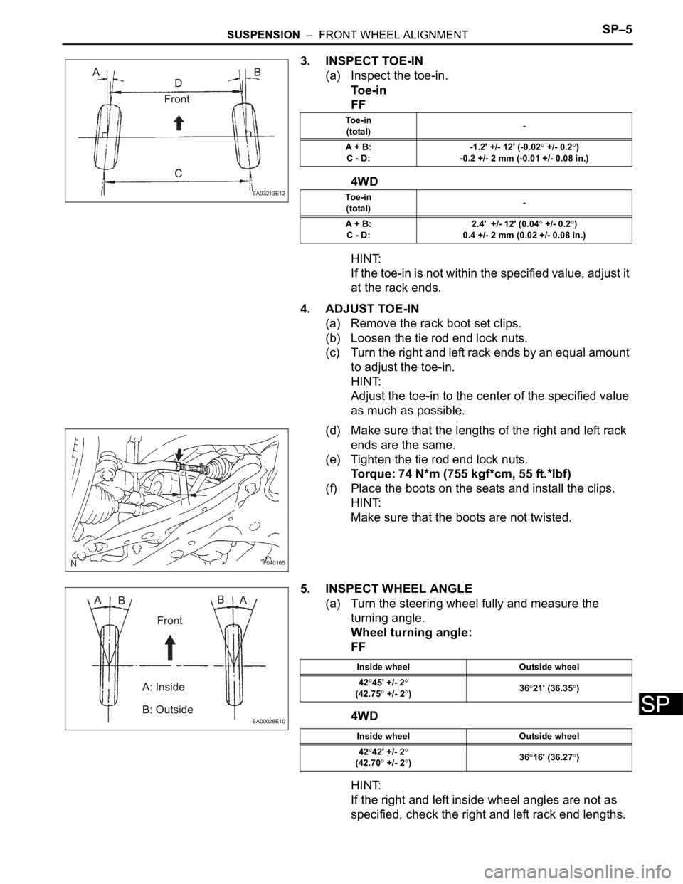
3. INSPECT TOE-IN
(a) Inspect the toe-in.
To e - i n
FF
4WD
HINT:
If the toe-in is not within the specified value, adjust it
at the rack ends.
4. ADJUST TOE-IN
(a) Remove the rack boot set clips.
(b) Loosen the tie rod end lock nuts.
(c) Turn the right and left rack ends by an equal amount
to adjust the toe-in.
HINT:
Adjust the toe-in to the center of the specified value
as much as possible.
(d) Make sure that the lengths of the right and left rack
ends are the same.
(e) Tighten the tie rod end lock nuts.
Torque: 74 N*m (755 kgf*cm, 55 ft.*lbf)
(f) Place the boots on the seats and install the clips.
HINT:
Make sure that the boots are not twisted.
5. INSPECT WHEEL ANGLE
(a) Turn the steering wheel fully and measure the
turning angle.
Wheel turning angle:
FF
4WD
HINT:
If the right and left inside wheel angles are not as
specified, check the right and left rack end lengths.
SA03213E12
To e - i n
(total)-
A + B:
C - D:-1.2' +/- 12' (-0.02
+/- 0.2)
-0.2 +/- 2 mm (-0.01 +/- 0.08 in.)
To e - i n
(total)-
A + B:
C - D:2.4' +/- 12' (0.04
+/- 0.2)
0.4 +/- 2 mm (0.02 +/- 0.08 in.)
F040165
SA00028E10
Inside wheel Outside wheel
42
45' +/- 2(42.75 +/- 2)3621' (36.35)
Inside wheel Outside wheel
42
42' +/- 2
(42.70 +/- 2)3616' (36.27)
Page 2188 of 3000
SP–6SUSPENSION – FRONT WHEEL ALIGNMENT
SP
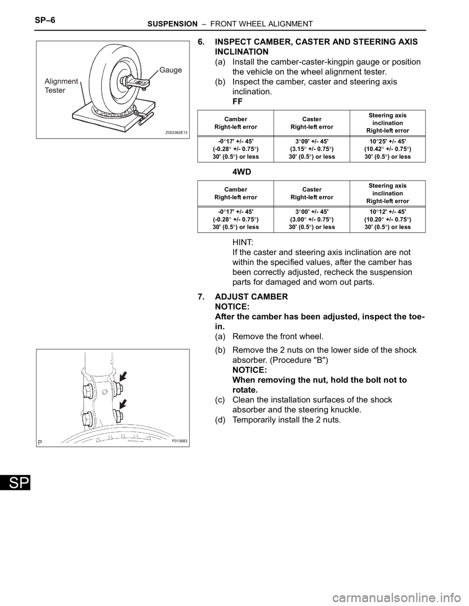
6. INSPECT CAMBER, CASTER AND STEERING AXIS
INCLINATION
(a) Install the camber-caster-kingpin gauge or position
the vehicle on the wheel alignment tester.
(b) Inspect the camber, caster and steering axis
inclination.
FF
4WD
HINT:
If the caster and steering axis inclination are not
within the specified values, after the camber has
been correctly adjusted, recheck the suspension
parts for damaged and worn out parts.
7. ADJUST CAMBER
NOTICE:
After the camber has been adjusted, inspect the toe-
in.
(a) Remove the front wheel.
(b) Remove the 2 nuts on the lower side of the shock
absorber. (Procedure "B")
NOTICE:
When removing the nut, hold the bolt not to
rotate.
(c) Clean the installation surfaces of the shock
absorber and the steering knuckle.
(d) Temporarily install the 2 nuts.
Z003382E13
Camber
Right-left errorCaster
Right-left errorSteering axis
inclination
Right-left error
-0
17' +/- 45'
(-0.28
+/- 0.75)
30' (0.5
) or less3
09' +/- 45'
(3.15
+/- 0.75)
30' (0.5
) or less10
25' +/- 45'
(10.42
+/- 0.75)
30' (0.5
) or less
Camber
Right-left errorCaster
Right-left errorSteering axis
inclination
Right-left error
-0
17' +/- 45'
(-0.28
+/- 0.75)
30' (0.5) or less3
00' +/- 45'
(3.00
+/- 0.75)
30' (0.5) or less10
12' +/- 45'
(10.20
+/- 0.75)
30' (0.5) or less
F013683
Page 2204 of 3000
SP–28SUSPENSION – FRONT STABILIZER BAR (for 2WD)
SP
REMOVAL
1. REMOVE FRONT WHEELS
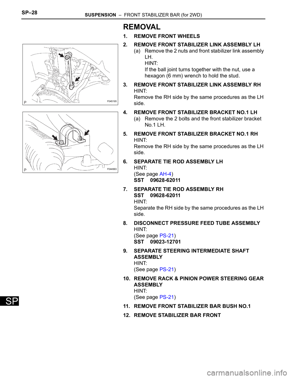
2. REMOVE FRONT STABILIZER LINK ASSEMBLY LH
(a) Remove the 2 nuts and front stabilizer link assembly
LH.
HINT:
If the ball joint turns together with the nut, use a
hexagon (6 mm) wrench to hold the stud.
3. REMOVE FRONT STABILIZER LINK ASSEMBLY RH
HINT:
Remove the RH side by the same procedures as the LH
side.
4. REMOVE FRONT STABILIZER BRACKET NO.1 LH
(a) Remove the 2 bolts and the front stabilizer bracket
No.1 LH.
5. REMOVE FRONT STABILIZER BRACKET NO.1 RH
HINT:
Remove the RH side by the same procedures as the LH
side.
6. SEPARATE TIE ROD ASSEMBLY LH
HINT:
(See page AH-4)
SST 09628-62011
7. SEPARATE TIE ROD ASSEMBLY RH
SST 09628-62011
HINT:
Separate the RH side by the same procedures as the LH
side.
8. DISCONNECT PRESSURE FEED TUBE ASSEMBLY
HINT:
(See page PS-21)
SST 09023-12701
9. SEPARATE STEERING INTERMEDIATE SHAFT
ASSEMBLY
HINT:
(See page PS-21)
10. REMOVE RACK & PINION POWER STEERING GEAR
ASSEMBLY
HINT:
(See page PS-21)
11. REMOVE FRONT STABILIZER BAR BUSH NO.1
12. REMOVE STABILIZER BAR FRONT
F045195
F044993
Page 2208 of 3000
SP–30SUSPENSION – FRONT STABILIZER BAR (for 2WD)
SP
INSTALLATION
1. INSTALL STABILIZER BAR FRONT
2. INSTALL FRONT STABILIZER BAR BUSH NO.1
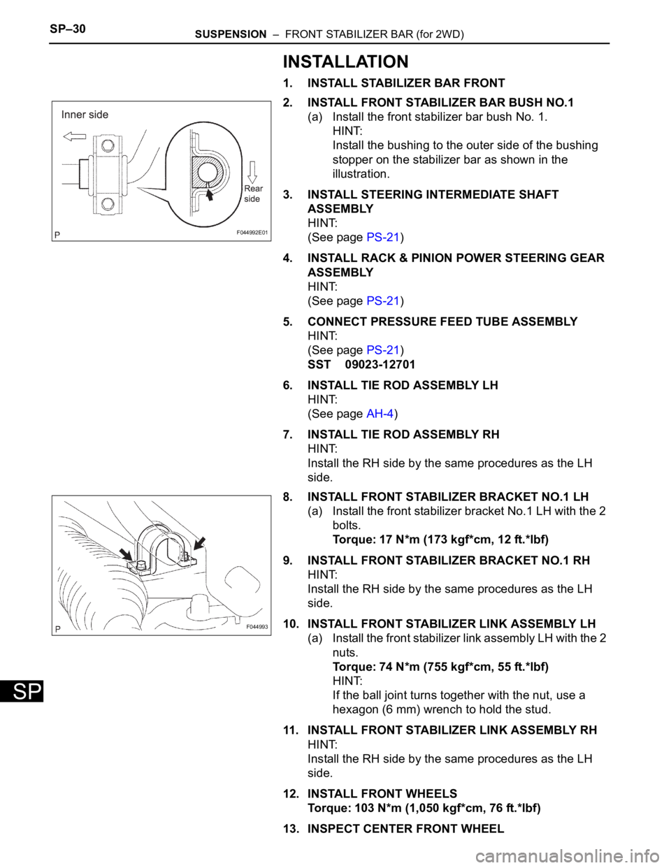
(a) Install the front stabilizer bar bush No. 1.
HINT:
Install the bushing to the outer side of the bushing
stopper on the stabilizer bar as shown in the
illustration.
3. INSTALL STEERING INTERMEDIATE SHAFT
ASSEMBLY
HINT:
(See page PS-21)
4. INSTALL RACK & PINION POWER STEERING GEAR
ASSEMBLY
HINT:
(See page PS-21)
5. CONNECT PRESSURE FEED TUBE ASSEMBLY
HINT:
(See page PS-21)
SST 09023-12701
6. INSTALL TIE ROD ASSEMBLY LH
HINT:
(See page AH-4)
7. INSTALL TIE ROD ASSEMBLY RH
HINT:
Install the RH side by the same procedures as the LH
side.
8. INSTALL FRONT STABILIZER BRACKET NO.1 LH
(a) Install the front stabilizer bracket No.1 LH with the 2
bolts.
Torque: 17 N*m (173 kgf*cm, 12 ft.*lbf)
9. INSTALL FRONT STABILIZER BRACKET NO.1 RH
HINT:
Install the RH side by the same procedures as the LH
side.
10. INSTALL FRONT STABILIZER LINK ASSEMBLY LH
(a) Install the front stabilizer link assembly LH with the 2
nuts.
Torque: 74 N*m (755 kgf*cm, 55 ft.*lbf)
HINT:
If the ball joint turns together with the nut, use a
hexagon (6 mm) wrench to hold the stud.
11. INSTALL FRONT STABILIZER LINK ASSEMBLY RH
HINT:
Install the RH side by the same procedures as the LH
side.
12. INSTALL FRONT WHEELS
Torque: 103 N*m (1,050 kgf*cm, 76 ft.*lbf)
13. INSPECT CENTER FRONT WHEEL
F044992E01
F044993