Page 2587 of 3000
BRAKE CONTROL – STEERING ANGLE SENSORBC–199
BC
REMOVAL
1. PRECAUTION
HINT:
See page RS-1
2. SEPARATE BATTERY NEGATIVE TERMINAL
3. PLACE FRONT WHEELS FACING STRAIGHT AHEAD
4. REMOVE HORN BUTTON ASSEMBLY (See page RS-
424)
5. REMOVE STEERING WHEEL ASSEMBLY (See page
SR-6)
6. REMOVE STEERING COLUMN COVER LWR (See
page RS-434)
7. REMOVE SPIRAL CABLE SUB-ASSEMBLY (See page
RS-434)
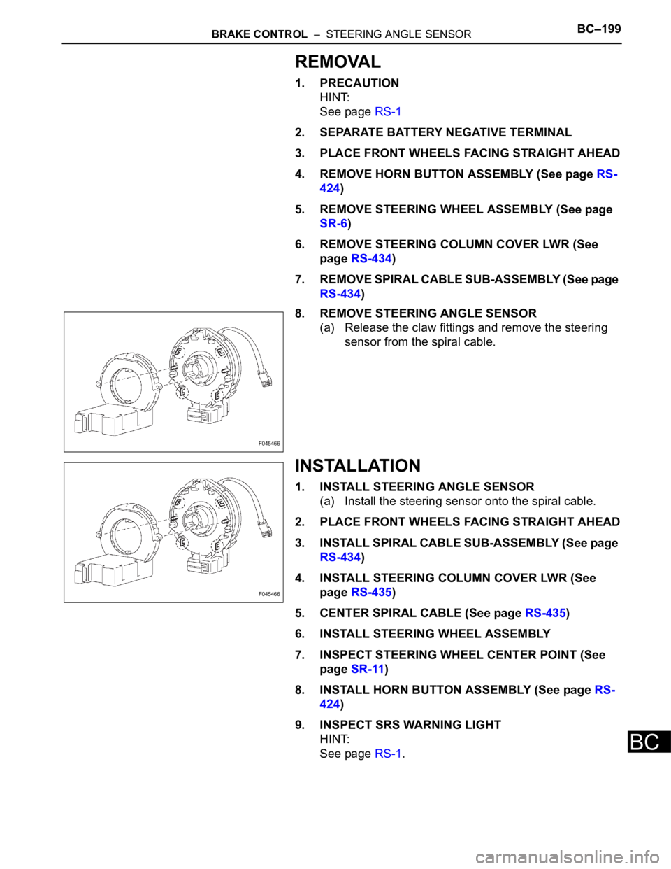
8. REMOVE STEERING ANGLE SENSOR
(a) Release the claw fittings and remove the steering
sensor from the spiral cable.
INSTALLATION
1. INSTALL STEERING ANGLE SENSOR
(a) Install the steering sensor onto the spiral cable.
2. PLACE FRONT WHEELS FACING STRAIGHT AHEAD
3. INSTALL SPIRAL CABLE SUB-ASSEMBLY (See page
RS-434)
4. INSTALL STEERING COLUMN COVER LWR (See
page RS-435)
5. CENTER SPIRAL CABLE (See page RS-435)
6. INSTALL STEERING WHEEL ASSEMBLY
7. INSPECT STEERING WHEEL CENTER POINT (See
page SR-11)
8. INSTALL HORN BUTTON ASSEMBLY (See page RS-
424)
9. INSPECT SRS WARNING LIGHT
HINT:
See page RS-1.
F045466
F045466
Page 2670 of 3000
SR–6STEERING COLUMN – STEERING COLUMN ASSEMBLY
SR
REMOVAL
1. PRECAUTION
HINT:
See page RS-1
2. DISCONNECT BATTERY NEGATIVE TERMINAL
Wait for 90 seconds after disconnecting the battery
terminal to prevent the airbag working.
3. PLACE FRONT WHEELS FACING STRAIGHT AHEAD
4. REMOVE STEERING WHEEL COVER LOWER NO.2
(See page RS-424)
5. REMOVE STEERING WHEEL COVER LOWER NO.3
(See page RS-424)
6. REMOVE HORN BUTTON ASSEMBLY (See page RS-
424)
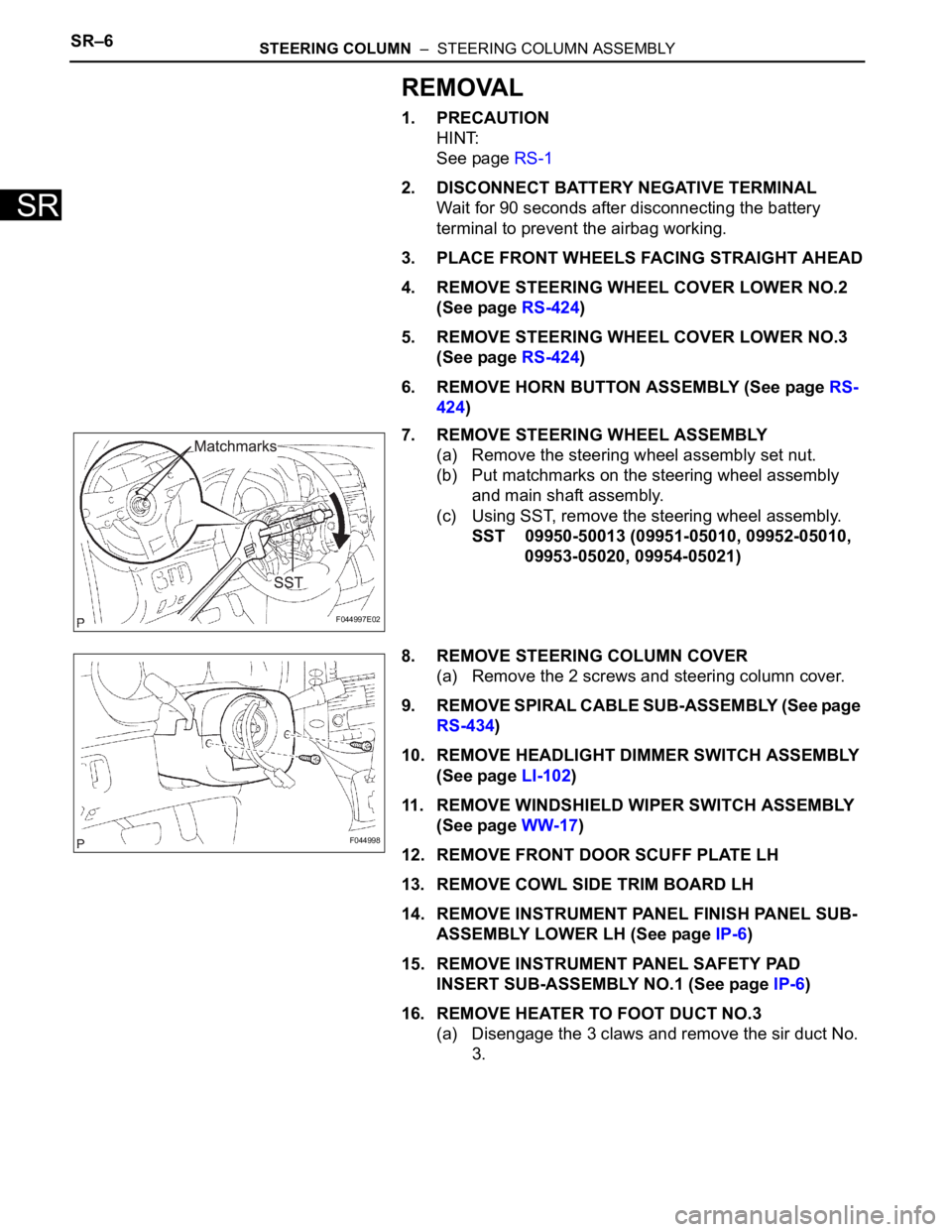
7. REMOVE STEERING WHEEL ASSEMBLY
(a) Remove the steering wheel assembly set nut.
(b) Put matchmarks on the steering wheel assembly
and main shaft assembly.
(c) Using SST, remove the steering wheel assembly.
SST 09950-50013 (09951-05010, 09952-05010,
09953-05020, 09954-05021)
8. REMOVE STEERING COLUMN COVER
(a) Remove the 2 screws and steering column cover.
9. REMOVE SPIRAL CABLE SUB-ASSEMBLY (See page
RS-434)
10. REMOVE HEADLIGHT DIMMER SWITCH ASSEMBLY
(See page LI-102)
11. REMOVE WINDSHIELD WIPER SWITCH ASSEMBLY
(See page WW-17)
12. REMOVE FRONT DOOR SCUFF PLATE LH
13. REMOVE COWL SIDE TRIM BOARD LH
14. REMOVE INSTRUMENT PANEL FINISH PANEL SUB-
ASSEMBLY LOWER LH (See page IP-6)
15. REMOVE INSTRUMENT PANEL SAFETY PAD
INSERT SUB-ASSEMBLY NO.1 (See page IP-6)
16. REMOVE HEATER TO FOOT DUCT NO.3
(a) Disengage the 3 claws and remove the sir duct No.
3.
F044997E02
F044998
Page 2675 of 3000
STEERING COLUMN – STEERING COLUMN ASSEMBLYSR–11
SR
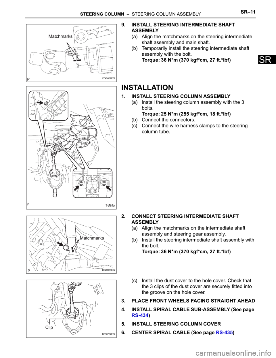
9. INSTALL STEERING INTERMEDIATE SHAFT
ASSEMBLY
(a) Align the matchmarks on the steering intermediate
shaft assembly and main shaft.
(b) Temporarily install the steering intermediate shaft
assembly with the bolt.
Torque: 36 N*m (370 kgf*cm, 27 ft.*lbf)
INSTALLATION
1. INSTALL STEERING COLUMN ASSEMBLY
(a) Install the steering column assembly with the 3
bolts.
Torque: 25 N*m (255 kgf*cm, 18 ft.*lbf)
(b) Connect the connectors.
(c) Connect the wire harness clamps to the steering
column tube.
2. CONNECT STEERING INTERMEDIATE SHAFT
ASSEMBLY
(a) Align the matchmarks on the intermediate shaft
assembly and steering gear assembly.
(b) Install the steering intermediate shaft assembly with
the bolt.
Torque: 36 N*m (370 kgf*cm, 27 ft.*lbf)
(c) Install the dust cover to the hole cover. Check that
the 3 clips of the dust cover are securely fitted into
the groove on the hole cover.
3. PLACE FRONT WHEELS FACING STRAIGHT AHEAD
4. INSTALL SPIRAL CABLE SUB-ASSEMBLY (See page
RS-434)
5. INSTALL STEERING COLUMN COVER
6. CENTER SPIRAL CABLE (See page RS-435)
F045002E02
F045001
D029986E02
D030704E02
Page 2676 of 3000
SR–12STEERING COLUMN – STEERING COLUMN ASSEMBLY
SR
7. INSTALL STEERING WHEEL ASSEMBLY
(a) Align the matchmarks on the steering wheel
assembly and steering main shaft assembly.
(b) Install the steering wheel assembly set nut.
Torque: 50 N*m (510 kgf*cm, 37 ft.*lbf)
(c) Connect the connector.
8. INSPECT STEERING WHEEL CENTER POINT
9. INSPECT HORN BUTTON ASSEMBLY (See page RS-
425)
10. INSTALL HORN BUTTON ASSEMBLY (See page RS-
424)
11. INSTALL STEERING WHEEL COVER LOWER NO.3
(See page RS-425)
12. INSTALL STEERING WHEEL COVER LOWER NO.2
(See page RS-425)
13. CONNECT BATTERY NEGATIVE TERMINAL
14. INSPECT SRS WARNING LIGHT (See page RS-436)
Page 2678 of 3000
SR–2STEERING COLUMN – STEERING SYSTEM
SR
PROBLEM SYMPTOMS TABLE
HINT:
Use the table below to help determine the cause of the
problem. Likely causes of the problem are indicated in
descending order. Check each suspected area in order.
Repair or replace the faulty parts or perform adjustments as
necessary.
STEERING SYSTEM
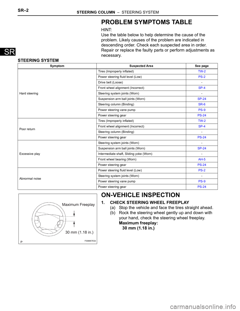
ON-VEHICLE INSPECTION
1. CHECK STEERING WHEEL FREEPLAY
(a) Stop the vehicle and face the tires straight ahead.
(b) Rock the steering wheel gently up and down with
your hand, check the steering wheel freeplay.
Maximum freeplay:
30 mm (1.18 in.)
Symptom Suspected Area See page
Hard steeringTires (Improperly inflated)TW-2
Power steering fluid level (Low)PS-2
Drive belt (Loose) -
Front wheel alignment (Incorrect)SP-4
Steering system joints (Worn) -
Suspension arm ball joints (Worn)SP-24
Steering column (Binding)SR-6
Power steering vane pumpPS-9
Power steering gearPS-24
Poor returnTires (Improperly inflated)TW-2
Front wheel alignment (Incorrect)SP-4
Steering column (Binding) -
Power steering gearPS-24
Excessive playSteering system joints (Worn) -
Suspension arm ball joints (Worn)SP-24
Intermediate shaft, Sliding yoke (Worn) -
Front wheel bearing (Worn)AH-5
Power steering gearPS-24
Abnormal noisePower steering fluid level (Low)PS-2
Steering system joints (Worn) -
Power steering vane pumpPS-9
Power steering gearPS-24
F008857E02
Page 2679 of 3000
SR–6STEERING COLUMN – STEERING COLUMN ASSEMBLY
SR
REMOVAL
1. PRECAUTION
HINT:
See page RS-1
2. DISCONNECT BATTERY NEGATIVE TERMINAL
Wait for 90 seconds after disconnecting the battery
terminal to prevent the airbag working.
3. PLACE FRONT WHEELS FACING STRAIGHT AHEAD
4. REMOVE STEERING WHEEL COVER LOWER NO.2
(See page RS-424)
5. REMOVE STEERING WHEEL COVER LOWER NO.3
(See page RS-424)
6. REMOVE HORN BUTTON ASSEMBLY (See page RS-
424)
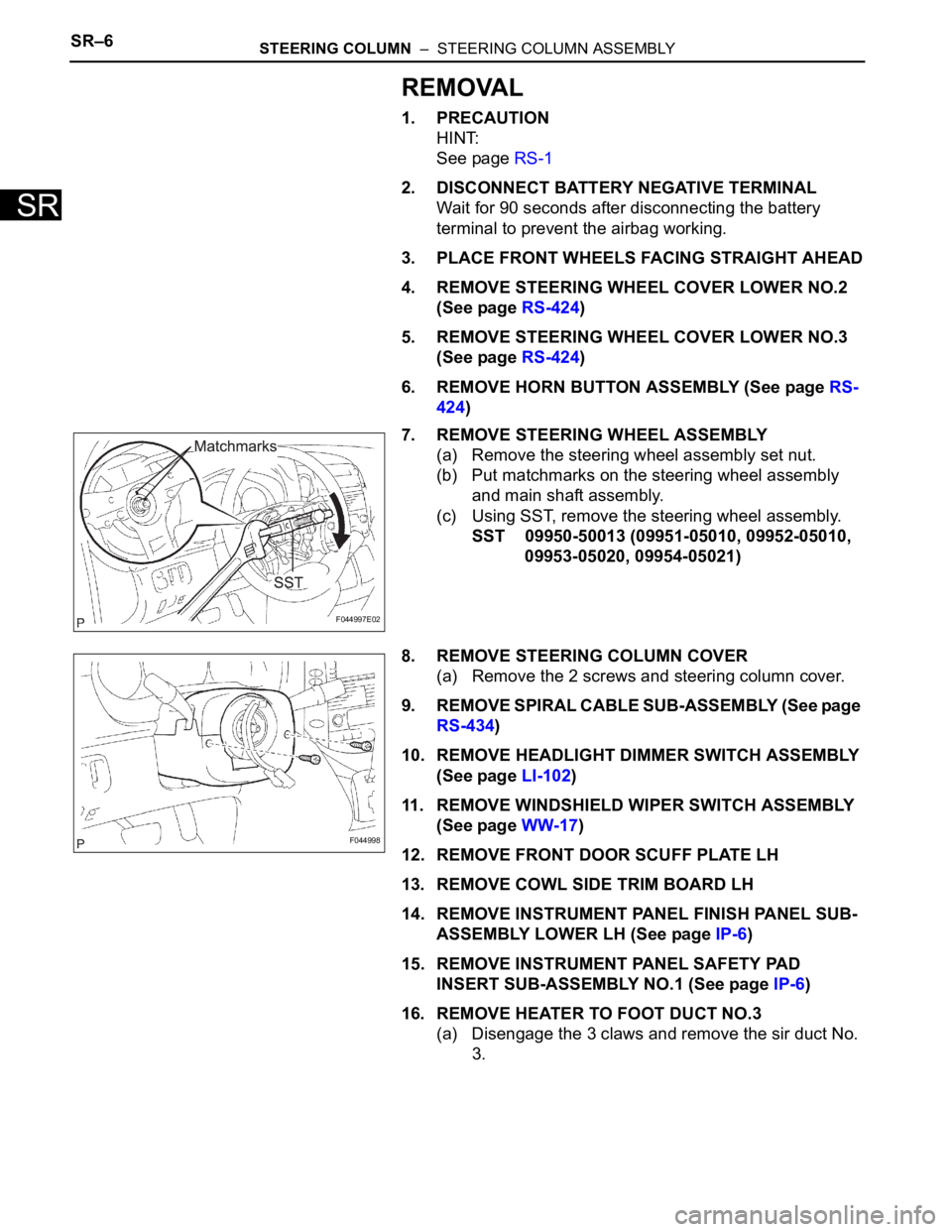
7. REMOVE STEERING WHEEL ASSEMBLY
(a) Remove the steering wheel assembly set nut.
(b) Put matchmarks on the steering wheel assembly
and main shaft assembly.
(c) Using SST, remove the steering wheel assembly.
SST 09950-50013 (09951-05010, 09952-05010,
09953-05020, 09954-05021)
8. REMOVE STEERING COLUMN COVER
(a) Remove the 2 screws and steering column cover.
9. REMOVE SPIRAL CABLE SUB-ASSEMBLY (See page
RS-434)
10. REMOVE HEADLIGHT DIMMER SWITCH ASSEMBLY
(See page LI-102)
11. REMOVE WINDSHIELD WIPER SWITCH ASSEMBLY
(See page WW-17)
12. REMOVE FRONT DOOR SCUFF PLATE LH
13. REMOVE COWL SIDE TRIM BOARD LH
14. REMOVE INSTRUMENT PANEL FINISH PANEL SUB-
ASSEMBLY LOWER LH (See page IP-6)
15. REMOVE INSTRUMENT PANEL SAFETY PAD
INSERT SUB-ASSEMBLY NO.1 (See page IP-6)
16. REMOVE HEATER TO FOOT DUCT NO.3
(a) Disengage the 3 claws and remove the sir duct No.
3.
F044997E02
F044998
Page 2684 of 3000
STEERING COLUMN – STEERING COLUMN ASSEMBLYSR–11
SR
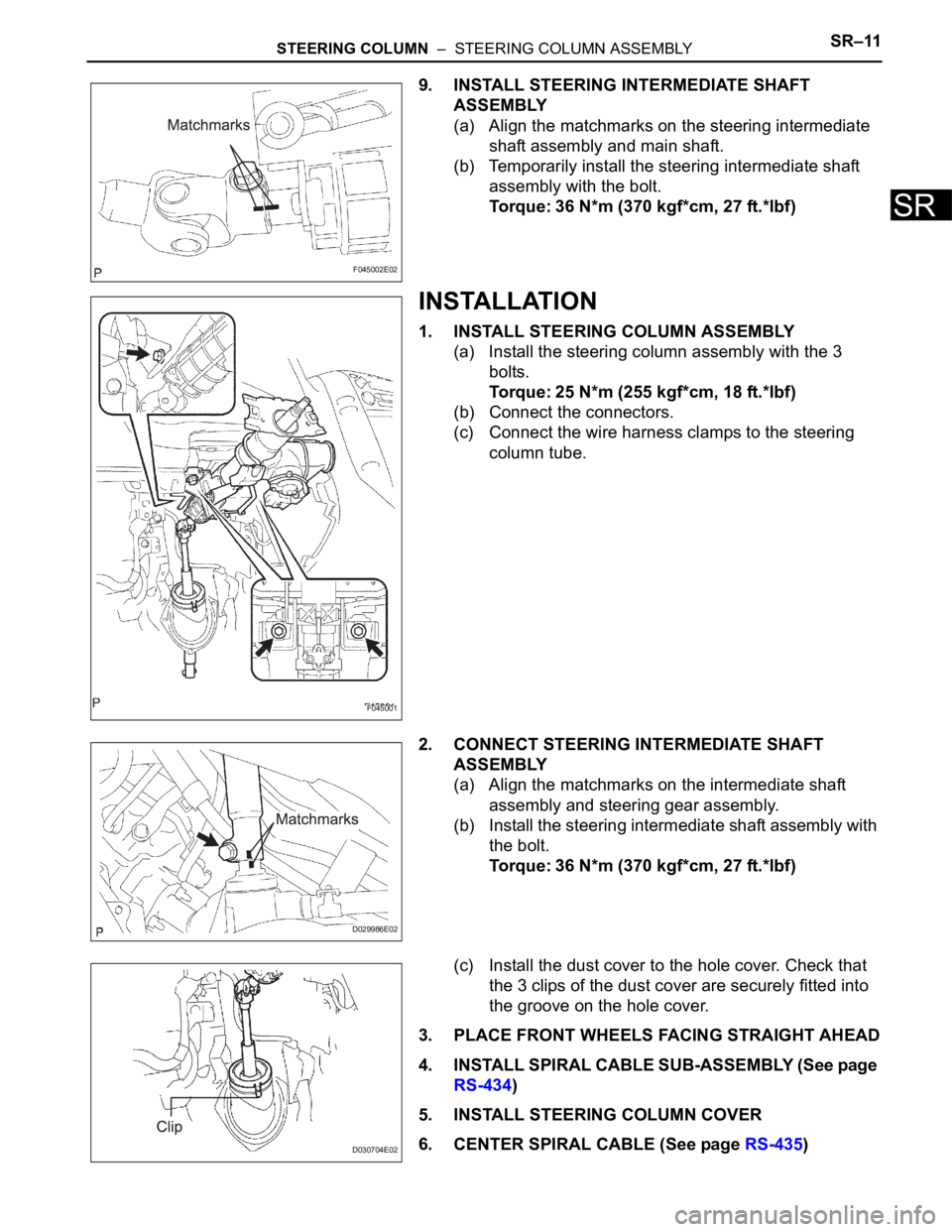
9. INSTALL STEERING INTERMEDIATE SHAFT
ASSEMBLY
(a) Align the matchmarks on the steering intermediate
shaft assembly and main shaft.
(b) Temporarily install the steering intermediate shaft
assembly with the bolt.
Torque: 36 N*m (370 kgf*cm, 27 ft.*lbf)
INSTALLATION
1. INSTALL STEERING COLUMN ASSEMBLY
(a) Install the steering column assembly with the 3
bolts.
Torque: 25 N*m (255 kgf*cm, 18 ft.*lbf)
(b) Connect the connectors.
(c) Connect the wire harness clamps to the steering
column tube.
2. CONNECT STEERING INTERMEDIATE SHAFT
ASSEMBLY
(a) Align the matchmarks on the intermediate shaft
assembly and steering gear assembly.
(b) Install the steering intermediate shaft assembly with
the bolt.
Torque: 36 N*m (370 kgf*cm, 27 ft.*lbf)
(c) Install the dust cover to the hole cover. Check that
the 3 clips of the dust cover are securely fitted into
the groove on the hole cover.
3. PLACE FRONT WHEELS FACING STRAIGHT AHEAD
4. INSTALL SPIRAL CABLE SUB-ASSEMBLY (See page
RS-434)
5. INSTALL STEERING COLUMN COVER
6. CENTER SPIRAL CABLE (See page RS-435)
F045002E02
F045001
D029986E02
D030704E02
Page 2685 of 3000
SR–12STEERING COLUMN – STEERING COLUMN ASSEMBLY
SR
7. INSTALL STEERING WHEEL ASSEMBLY
(a) Align the matchmarks on the steering wheel
assembly and steering main shaft assembly.
(b) Install the steering wheel assembly set nut.
Torque: 50 N*m (510 kgf*cm, 37 ft.*lbf)
(c) Connect the connector.
8. INSPECT STEERING WHEEL CENTER POINT
9. INSPECT HORN BUTTON ASSEMBLY (See page RS-
425)
10. INSTALL HORN BUTTON ASSEMBLY (See page RS-
424)
11. INSTALL STEERING WHEEL COVER LOWER NO.3
(See page RS-425)
12. INSTALL STEERING WHEEL COVER LOWER NO.2
(See page RS-425)
13. CONNECT BATTERY NEGATIVE TERMINAL
14. INSPECT SRS WARNING LIGHT (See page RS-436)