Page 2209 of 3000
SUSPENSION – FRONT STABILIZER BAR (for 2WD)SP–31
SP
14. INSPECT STEERING WHEEL CENTER POINT
15. ADD POWER STEERING FLUID
16. BLEED POWER STEERING FLUID
HINT:
(See page SP-26)
17. CHECK POWER STEERING FLUID LEAKAGE
18. INSPECT AND ADJUST FRONT WHEEL ALIGNMENT
HINT:
(See page SP-4)
Page 2212 of 3000
SUSPENSION – FRONT STABILIZER BAR (for 4WD)SP–35
SP
REMOVAL
1. REMOVE FRONT WHEELS
2. REMOVE FRONT STABILIZER LINK ASSEMBLY LH
HINT:
(See page SP-26)
3. REMOVE FRONT STABILIZER LINK ASSEMBLY RH
HINT:
Remove the RH side by the same procedures as the LH
side.
4. REMOVE CENTER EXHAUST PIPE ASSEMBLY
HINT:
(See page EX-8)
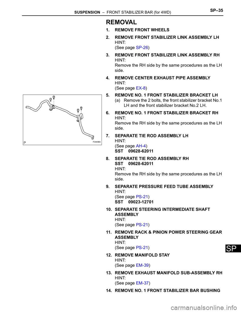
5. REMOVE NO. 1 FRONT STABILIZER BRACKET LH
(a) Remove the 2 bolts, the front stabilizer bracket No.1
LH and the front stabilizer bracket No.2 LH.
6. REMOVE NO. 1 FRONT STABILIZER BRACKET RH
HINT:
Remove the RH side by the same procedures as the LH
side.
7. SEPARATE TIE ROD ASSEMBLY LH
HINT:
(See page AH-4)
SST 09628-62011
8. SEPARATE TIE ROD ASSEMBLY RH
SST 09628-62011
HINT:
Remove the RH side by the same procedures as the LH
side.
9. SEPARATE PRESSURE FEED TUBE ASSEMBLY
HINT:
(See page PS-21)
SST 09023-12701
10. SEPARATE STEERING INTERMEDIATE SHAFT
ASSEMBLY
HINT:
(See page PS-21)
11. REMOVE RACK & PINION POWER STEERING GEAR
ASSEMBLY
HINT:
(See page PS-21)
12. REMOVE MANIFOLD STAY
HINT:
(See page EM-39)
13. REMOVE EXHAUST MANIFOLD SUB-ASSEMBLY RH
HINT:
(See page EM-37)
14. REMOVE NO. 1 FRONT STABILIZER BAR BUSHING
F044966
Page 2216 of 3000
SP–28SUSPENSION – FRONT STABILIZER BAR (for 2WD)
SP
REMOVAL
1. REMOVE FRONT WHEELS
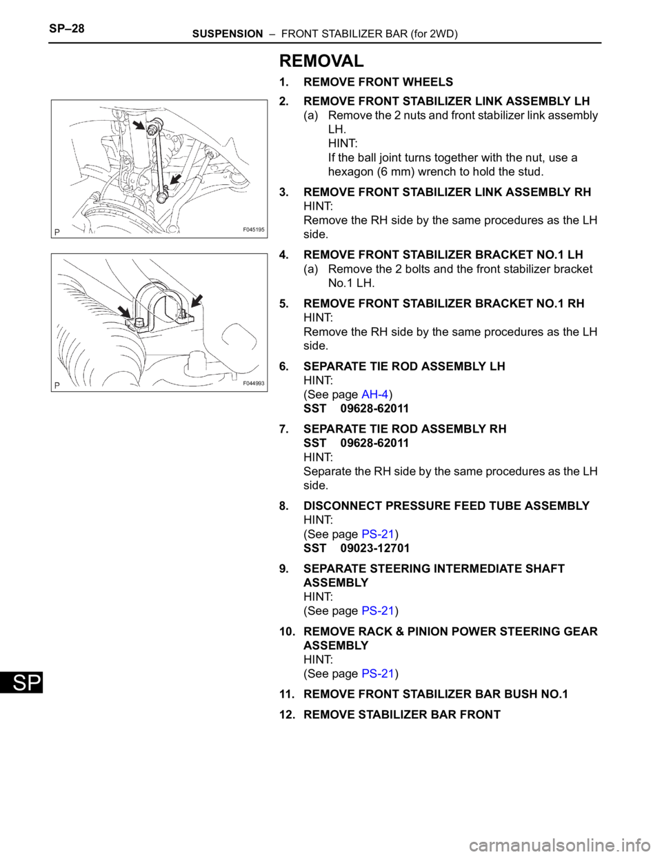
2. REMOVE FRONT STABILIZER LINK ASSEMBLY LH
(a) Remove the 2 nuts and front stabilizer link assembly
LH.
HINT:
If the ball joint turns together with the nut, use a
hexagon (6 mm) wrench to hold the stud.
3. REMOVE FRONT STABILIZER LINK ASSEMBLY RH
HINT:
Remove the RH side by the same procedures as the LH
side.
4. REMOVE FRONT STABILIZER BRACKET NO.1 LH
(a) Remove the 2 bolts and the front stabilizer bracket
No.1 LH.
5. REMOVE FRONT STABILIZER BRACKET NO.1 RH
HINT:
Remove the RH side by the same procedures as the LH
side.
6. SEPARATE TIE ROD ASSEMBLY LH
HINT:
(See page AH-4)
SST 09628-62011
7. SEPARATE TIE ROD ASSEMBLY RH
SST 09628-62011
HINT:
Separate the RH side by the same procedures as the LH
side.
8. DISCONNECT PRESSURE FEED TUBE ASSEMBLY
HINT:
(See page PS-21)
SST 09023-12701
9. SEPARATE STEERING INTERMEDIATE SHAFT
ASSEMBLY
HINT:
(See page PS-21)
10. REMOVE RACK & PINION POWER STEERING GEAR
ASSEMBLY
HINT:
(See page PS-21)
11. REMOVE FRONT STABILIZER BAR BUSH NO.1
12. REMOVE STABILIZER BAR FRONT
F045195
F044993
Page 2219 of 3000
SP–38SUSPENSION – FRONT STABILIZER BAR (for 4WD)
SP
13. INSTALL FRONT STABILIZER LINK ASSEMBLY LH
HINT:
(See page AH-4)
14. INSTALL FRONT STABILIZER LINK ASSEMBLY RH
HINT:
Install the RH side by the same procedures as the LH
side.
15. INSTALL FRONT WHEELS
16. INSPECT CENTER FRONT WHEEL
17. INSPECT STEERING WHEEL CENTER POINT
18. ADD POWER STEERING FLUID
19. BLEED POWER STEERING FLUID
HINT:
(See page PS-6)
20. CHECK POWER STEERING FLUID LEAKAGE
21. INSPECT AND ADJUST FRONT WHEEL ALIGNMENT
HINT:
(See page SP-4)
Page 2220 of 3000
SUSPENSION – FRONT STABILIZER BAR (for 4WD)SP–35
SP
REMOVAL
1. REMOVE FRONT WHEELS
2. REMOVE FRONT STABILIZER LINK ASSEMBLY LH
HINT:
(See page SP-26)
3. REMOVE FRONT STABILIZER LINK ASSEMBLY RH
HINT:
Remove the RH side by the same procedures as the LH
side.
4. REMOVE CENTER EXHAUST PIPE ASSEMBLY
HINT:
(See page EX-8)
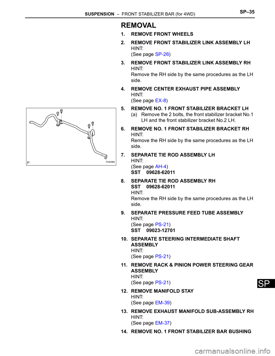
5. REMOVE NO. 1 FRONT STABILIZER BRACKET LH
(a) Remove the 2 bolts, the front stabilizer bracket No.1
LH and the front stabilizer bracket No.2 LH.
6. REMOVE NO. 1 FRONT STABILIZER BRACKET RH
HINT:
Remove the RH side by the same procedures as the LH
side.
7. SEPARATE TIE ROD ASSEMBLY LH
HINT:
(See page AH-4)
SST 09628-62011
8. SEPARATE TIE ROD ASSEMBLY RH
SST 09628-62011
HINT:
Remove the RH side by the same procedures as the LH
side.
9. SEPARATE PRESSURE FEED TUBE ASSEMBLY
HINT:
(See page PS-21)
SST 09023-12701
10. SEPARATE STEERING INTERMEDIATE SHAFT
ASSEMBLY
HINT:
(See page PS-21)
11. REMOVE RACK & PINION POWER STEERING GEAR
ASSEMBLY
HINT:
(See page PS-21)
12. REMOVE MANIFOLD STAY
HINT:
(See page EM-39)
13. REMOVE EXHAUST MANIFOLD SUB-ASSEMBLY RH
HINT:
(See page EM-37)
14. REMOVE NO. 1 FRONT STABILIZER BAR BUSHING
F044966
Page 2223 of 3000
SP–38SUSPENSION – FRONT STABILIZER BAR (for 4WD)
SP
13. INSTALL FRONT STABILIZER LINK ASSEMBLY LH
HINT:
(See page AH-4)
14. INSTALL FRONT STABILIZER LINK ASSEMBLY RH
HINT:
Install the RH side by the same procedures as the LH
side.
15. INSTALL FRONT WHEELS
16. INSPECT CENTER FRONT WHEEL
17. INSPECT STEERING WHEEL CENTER POINT
18. ADD POWER STEERING FLUID
19. BLEED POWER STEERING FLUID
HINT:
(See page PS-6)
20. CHECK POWER STEERING FLUID LEAKAGE
21. INSPECT AND ADJUST FRONT WHEEL ALIGNMENT
HINT:
(See page SP-4)
Page 2368 of 3000
BC–4BRAKE CONTROL – ANTI-LOCK BRAKE SYSTEM
BC
TEST MODE PROCEDURE
1. SPEED SENSOR SIGNAL CHECK (WHEN USING SST
CHECK WIRE):
HINT:
• If the ignition switch is turned from the ON to the ACC
or LOCK position during Test Mode, the DTCs of the
signal check function will be erased.
(a) Turn the ignition switch off.
(b) Check that the steering wheel is in the straight-
ahead position and move the shift lever to the P
position (Automatic Transmission) or apply the
parking brake (Manual Transmission).
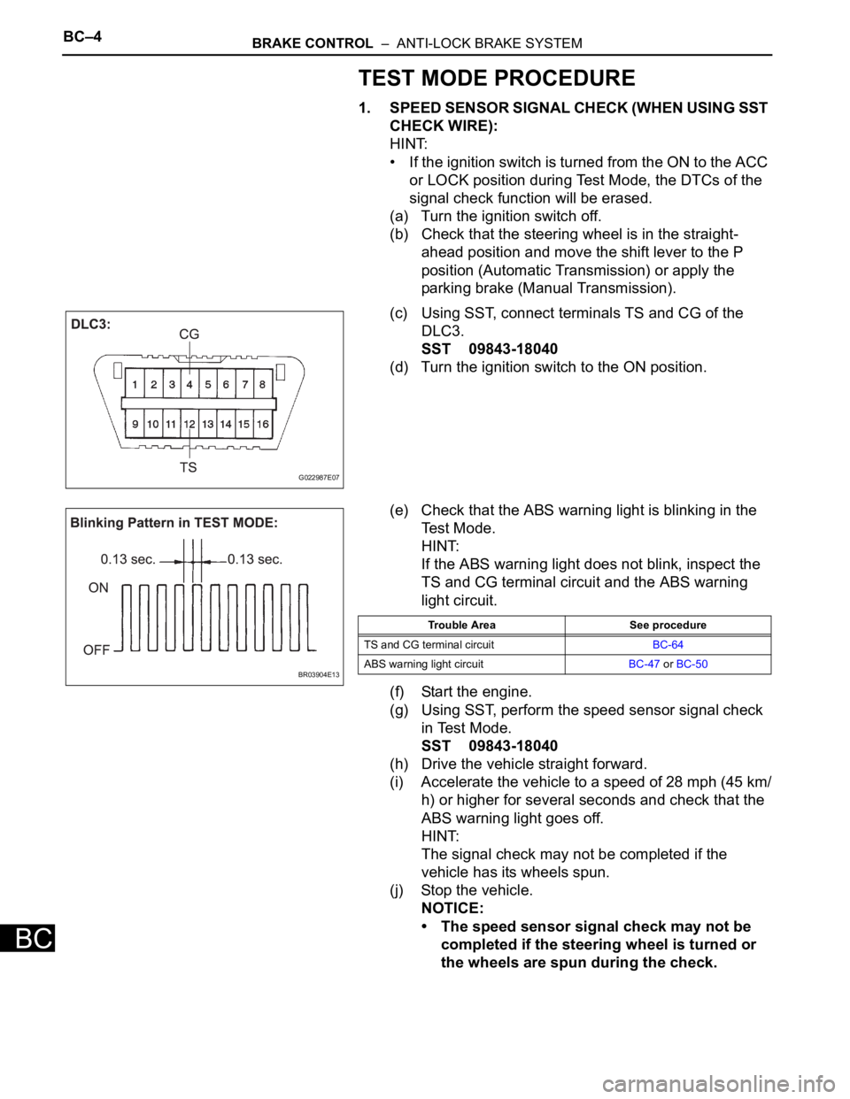
(c) Using SST, connect terminals TS and CG of the
DLC3.
SST 09843-18040
(d) Turn the ignition switch to the ON position.
(e) Check that the ABS warning light is blinking in the
Test Mode.
HINT:
If the ABS warning light does not blink, inspect the
TS and CG terminal circuit and the ABS warning
light circuit.
(f) Start the engine.
(g) Using SST, perform the speed sensor signal check
in Test Mode.
SST 09843-18040
(h) Drive the vehicle straight forward.
(i) Accelerate the vehicle to a speed of 28 mph (45 km/
h) or higher for several seconds and check that the
ABS warning light goes off.
HINT:
The signal check may not be completed if the
vehicle has its wheels spun.
(j) Stop the vehicle.
NOTICE:
• The speed sensor signal check may not be
completed if the steering wheel is turned or
the wheels are spun during the check.
G022987E07
BR03904E13
Trouble Area See procedure
TS and CG terminal circuitBC-64
ABS warning light circuitBC-47 or BC-50
Page 2370 of 3000
BC–6BRAKE CONTROL – ANTI-LOCK BRAKE SYSTEM
BC
HINT:
The codes in this table are output only in Test Mode
(signal check).
4. SPEED SENSOR SIGNAL CHECK (WHEN USING
INTELLIGENT TESTER):
HINT:
• If the ignition switch is turned from the ON to the ACC
or LOCK position during Test Mode, DTCs of the
signal check function will be erased.
• During Test Mode, the ECU records all DTCs of the
signal check function. By performing the signal check,
the codes are erased if normality is confirmed. The
remaining codes are the codes where an abnormality
was found.
(a) Turn the ignition switch off.
(b) Check that the steering wheel is in the straight-
ahead position.
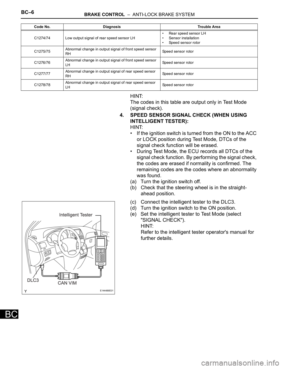
(c) Connect the intelligent tester to the DLC3.
(d) Turn the ignition switch to the ON position.
(e) Set the intelligent tester to Test Mode (select
"SIGNAL CHECK").
HINT:
Refer to the intelligent tester operator's manual for
further details.
C1274/74 Low output signal of rear speed sensor LH• Rear speed sensor LH
• Sensor installation
• Speed sensor rotor
C1275/75Abnormal change in output signal of front speed sensor
RHSpeed sensor rotor
C1276/76Abnormal change in output signal of front speed sensor
LHSpeed sensor rotor
C1277/77Abnormal change in output signal of rear speed sensor
RHSpeed sensor rotor
C1278/78Abnormal change in output signal of rear speed sensor
LHSpeed sensor rotor Code No. Diagnosis Trouble Area
E144486E01