Page 189 of 3000
STEERING COLUMN – STEERING SYSTEMSR–3
SR
REPAIR
1. STEERING OFF CENTER REPAIR PROCEDURE
(a) Inspect steering wheel off center.
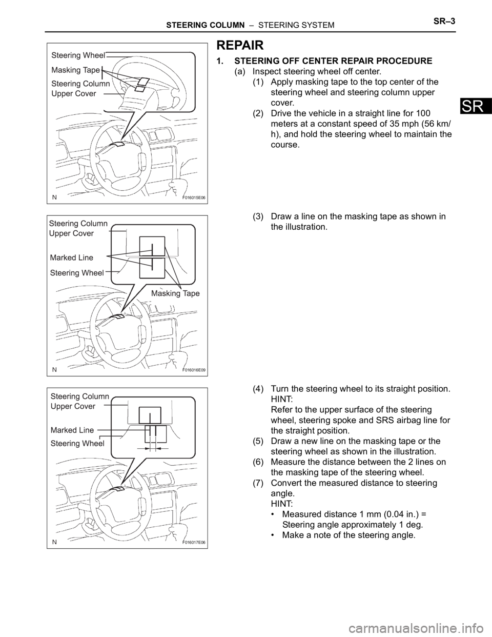
(1) Apply masking tape to the top center of the
steering wheel and steering column upper
cover.
(2) Drive the vehicle in a straight line for 100
meters at a constant speed of 35 mph (56 km/
h), and hold the steering wheel to maintain the
course.
(3) Draw a line on the masking tape as shown in
the illustration.
(4) Turn the steering wheel to its straight position.
HINT:
Refer to the upper surface of the steering
wheel, steering spoke and SRS airbag line for
the straight position.
(5) Draw a new line on the masking tape or the
steering wheel as shown in the illustration.
(6) Measure the distance between the 2 lines on
the masking tape of the steering wheel.
(7) Convert the measured distance to steering
angle.
HINT:
• Measured distance 1 mm (0.04 in.) =
Steering angle approximately 1 deg.
• Make a note of the steering angle.
F016015E06
F016016E09
F016017E06
Page 191 of 3000
POWER STEERING – VANE PUMPPS–9
PS
REMOVAL
1. DRAIN POWER STEERING FLUID
2. REMOVE FRONT WHEEL RH
3. REMOVE FRONT FENDER APRON SEAL RH (See
page EM-26)
4. REMOVE FAN AND GENERATOR V BELT (See page
EM-6)
5. DISCONNECT NO. 1 FLUID RESERVOIR TO PUMP
HOSE
(a) Slide the clip and disconnect the No. 1 fluid
reservoir to pump hose from the vane pump
assembly.
6. DISCONNECT PRESSURE FEED TUBE ASSEMBLY
(a) Remove the union bolt and disconnect the pressure
feed tube assembly from the vane pump assembly.
(b) Remove the gasket from the pressure feed tube
assembly.
7. DISCONNECT POWER STEERING FLUID PRESSURE
SWITCH CONNECTOR
(a) Disconnect the power steering fluid pressure switch
connector.
C133174E02
C161546
C161547
Page 289 of 3000
INSTRUMENT PANEL – INSTRUMENT PANEL SAFETY PADIP–5
IP
REMOVAL
1. BOLT, SCREW AND NUT TABLE
(a) The bolts, the screws and the nuts, which are
necessary for installation and removal of the
instrument panel are shown in the illustration below
with alphabets.
2. DISCONNECT BATTERY NEGATIVE TERMINAL (See
page RS-423)
3. REMOVE STEERING WHEEL COVER LOWER NO.2
4. REMOVE STEERING WHEEL COVER LOWER NO.3
5. REMOVE HORN BUTTON ASSEMBLY (See page RS-
424)
6. REMOVE STEERING WHEEL ASSEMBLY (See page
SR-6)
7. REMOVE STEERING COLUMN COVER (See page
RS-434)
8. REMOVE HEADLIGHT DIMMER SWITCH ASSEMBLY
(See page LI-102)
9. REMOVE WINDSHIELD WIPER SWITCH ASSEMBLY
(See page WW-17)
B066709E01
Page 318 of 3000
2GR-FE ENGINE CONTROL SYSTEM – SFI SYSTEMES–1
ES
SFI SYSTEM
PRECAUTION
1. INITIALIZATION
NOTICE:
• Perform RESET MEMORY (AT initialization) when
replacing the automatic transaxle assembly, engine
assembly or ECM (See page AX-16).
• Perform REGISTRATION (VIN registration) when
replacing the ECM (See page ES-15).
HINT:
Initialization cannot be completed by only removing the
battery.
2. FOR USING INTELLIGENT TESTER
CAUTION:
Observe the following items for safety reasons:
• Before using the tester, read the instruction
manual.
• Prevent the tester cable from being caught on the
pedals, shift lever and steering wheel when
driving with the tester connected to the vehicle.
• When driving the vehicle for testing purposes
using the tester, two persons are required. One is
for driving the vehicle, and the other operates the
tester.
3. FOR USING BATTERY DURING INSPECTION
(a) While using the battery during inspection, do not
bring the positive and negative tester probes too
close to each other as a short circuit may occur.
4. COOLING FAN SYSTEM
NOTICE:
• When the ignition switch is turned off and the engine
temperature is high, the cooling fans may operate for
approximately 3 minutes.
• After turning the ignition switch off, keep hands and
objects away from the fans when they are operating.
HINT:
If all of the following are met for a certain period of time during
a few minute period immediately before the engine is
stopped, the electric fans will continue to operate for 3
minutes after the engine is stopped. This is performed to
ensure restartability and stabilize idle speed.
– The intelligent tester indicates a very high coolant
temperature.
– The intelligent tester indicates a high outside air
temperature.
– The vehicle has been driven under high load (driving on an
uphill or equivalent).
The following sensors are used for this control:
– Coolant temperature sensor
– Outside air temperature sensor
–MAF sensor
– Vehicle speed sensors
Page 879 of 3000
EM–622GR-FE ENGINE MECHANICAL – ENGINE ASSEMBLY
EM
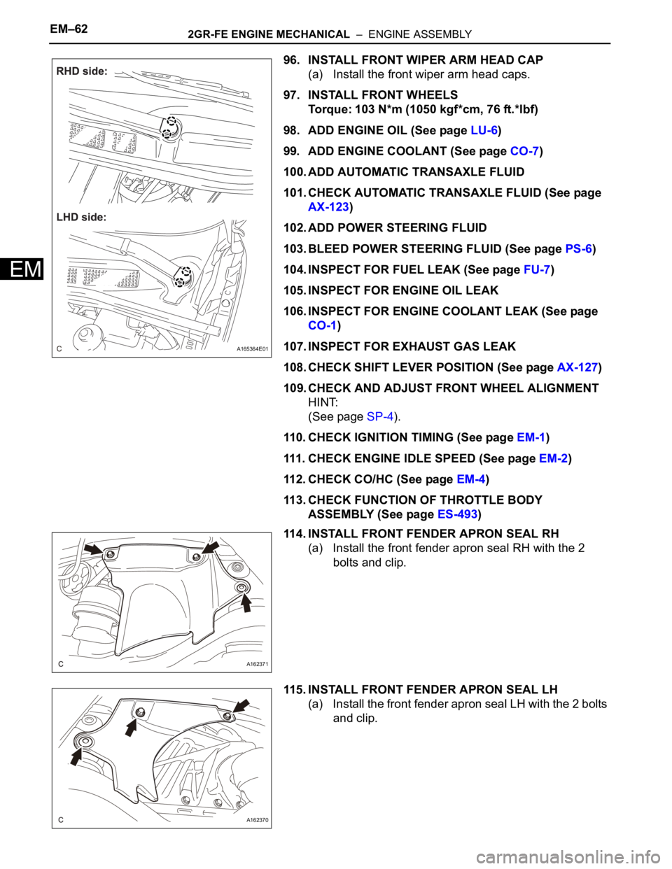
96. INSTALL FRONT WIPER ARM HEAD CAP
(a) Install the front wiper arm head caps.
97. INSTALL FRONT WHEELS
Torque: 103 N*m (1050 kgf*cm, 76 ft.*lbf)
98. ADD ENGINE OIL (See page LU-6)
99. ADD ENGINE COOLANT (See page CO-7)
100. ADD AUTOMATIC TRANSAXLE FLUID
101. CHECK AUTOMATIC TRANSAXLE FLUID (See page
AX-123)
102. ADD POWER STEERING FLUID
103. BLEED POWER STEERING FLUID (See page PS-6)
104. INSPECT FOR FUEL LEAK (See page FU-7)
105. INSPECT FOR ENGINE OIL LEAK
106. INSPECT FOR ENGINE COOLANT LEAK (See page
CO-1)
107. INSPECT FOR EXHAUST GAS LEAK
108. CHECK SHIFT LEVER POSITION (See page AX-127)
109. CHECK AND ADJUST FRONT WHEEL ALIGNMENT
HINT:
(See page SP-4).
110. CHECK IGNITION TIMING (See page EM-1)
111. CHECK ENGINE IDLE SPEED (See page EM-2)
112. CHECK CO/HC (See page EM-4)
113. CHECK FUNCTION OF THROTTLE BODY
ASSEMBLY (See page ES-493)
114. INSTALL FRONT FENDER APRON SEAL RH
(a) Install the front fender apron seal RH with the 2
bolts and clip.
115. INSTALL FRONT FENDER APRON SEAL LH
(a) Install the front fender apron seal LH with the 2 bolts
and clip.
A165364E01
A162371
A162370
Page 1021 of 3000
EM–622GR-FE ENGINE MECHANICAL – ENGINE ASSEMBLY
EM
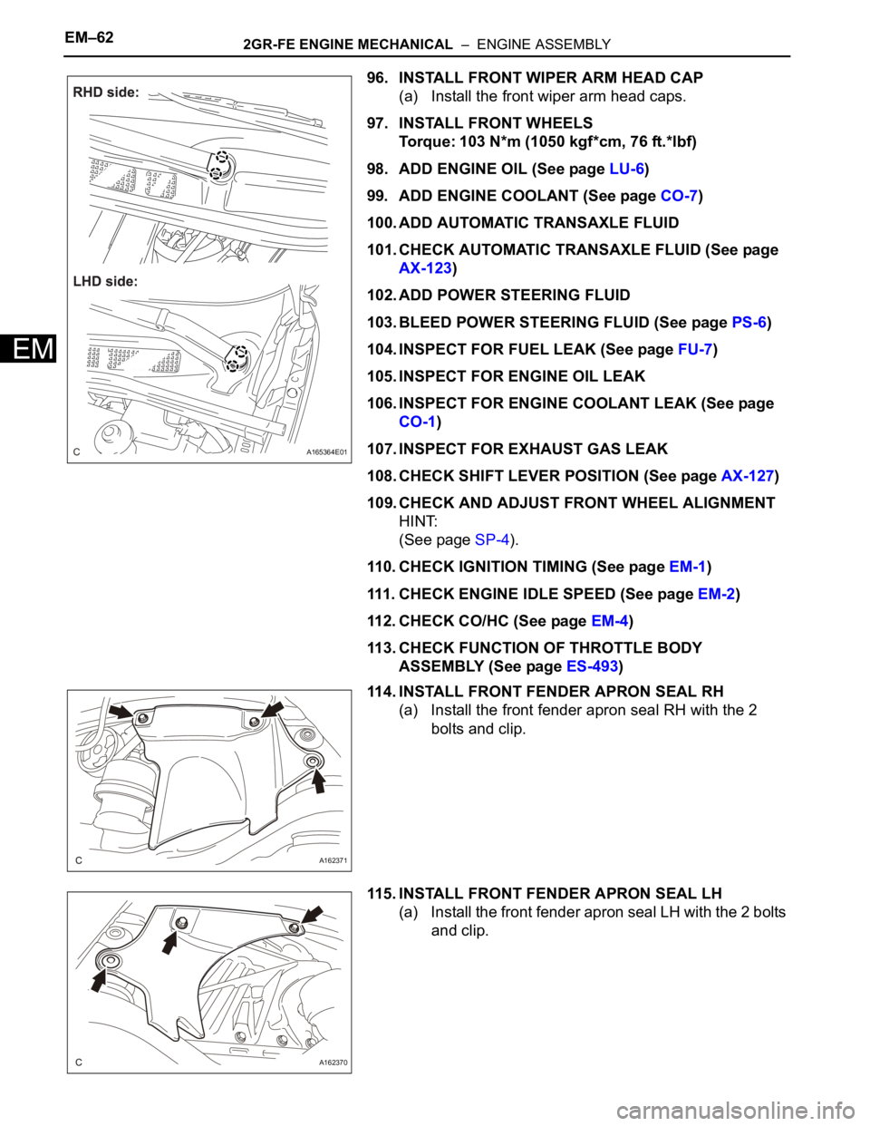
96. INSTALL FRONT WIPER ARM HEAD CAP
(a) Install the front wiper arm head caps.
97. INSTALL FRONT WHEELS
Torque: 103 N*m (1050 kgf*cm, 76 ft.*lbf)
98. ADD ENGINE OIL (See page LU-6)
99. ADD ENGINE COOLANT (See page CO-7)
100. ADD AUTOMATIC TRANSAXLE FLUID
101. CHECK AUTOMATIC TRANSAXLE FLUID (See page
AX-123)
102. ADD POWER STEERING FLUID
103. BLEED POWER STEERING FLUID (See page PS-6)
104. INSPECT FOR FUEL LEAK (See page FU-7)
105. INSPECT FOR ENGINE OIL LEAK
106. INSPECT FOR ENGINE COOLANT LEAK (See page
CO-1)
107. INSPECT FOR EXHAUST GAS LEAK
108. CHECK SHIFT LEVER POSITION (See page AX-127)
109. CHECK AND ADJUST FRONT WHEEL ALIGNMENT
HINT:
(See page SP-4).
110. CHECK IGNITION TIMING (See page EM-1)
111. CHECK ENGINE IDLE SPEED (See page EM-2)
112. CHECK CO/HC (See page EM-4)
113. CHECK FUNCTION OF THROTTLE BODY
ASSEMBLY (See page ES-493)
114. INSTALL FRONT FENDER APRON SEAL RH
(a) Install the front fender apron seal RH with the 2
bolts and clip.
115. INSTALL FRONT FENDER APRON SEAL LH
(a) Install the front fender apron seal LH with the 2 bolts
and clip.
A165364E01
A162371
A162370
Page 1339 of 3000
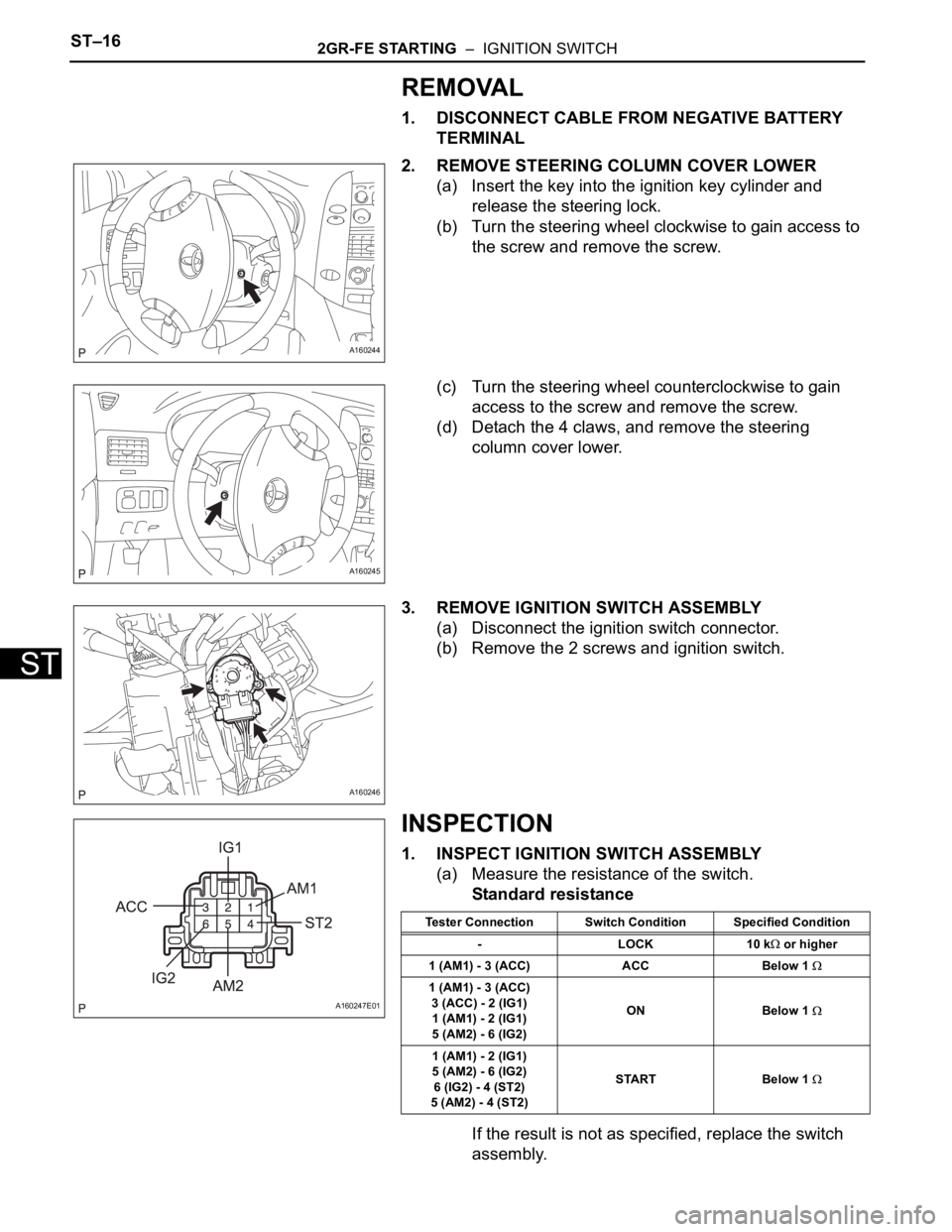
ST–162GR-FE STARTING – IGNITION SWITCH
ST
REMOVAL
1. DISCONNECT CABLE FROM NEGATIVE BATTERY
TERMINAL
2. REMOVE STEERING COLUMN COVER LOWER
(a) Insert the key into the ignition key cylinder and
release the steering lock.
(b) Turn the steering wheel clockwise to gain access to
the screw and remove the screw.
(c) Turn the steering wheel counterclockwise to gain
access to the screw and remove the screw.
(d) Detach the 4 claws, and remove the steering
column cover lower.
3. REMOVE IGNITION SWITCH ASSEMBLY
(a) Disconnect the ignition switch connector.
(b) Remove the 2 screws and ignition switch.
INSPECTION
1. INSPECT IGNITION SWITCH ASSEMBLY
(a) Measure the resistance of the switch.
Standard resistance
If the result is not as specified, replace the switch
assembly.
A160244
A160245
A160246
A160247E01
Tester Connection Switch Condition Specified Condition
-LOCK10 k
or higher
1 (AM1) - 3 (ACC) ACC Below 1
1 (AM1) - 3 (ACC)
3 (ACC) - 2 (IG1)
1 (AM1) - 2 (IG1)
5 (AM2) - 6 (IG2)ON Below 1
1 (AM1) - 2 (IG1)
5 (AM2) - 6 (IG2)
6 (IG2) - 4 (ST2)
5 (AM2) - 4 (ST2)START Below 1
Page 1340 of 3000
2GR-FE STARTING – IGNITION SWITCHST–17
ST
INSTALLATION
1. INSTALL IGNITION SWITCH ASSEMBLY
(a) Install the ignition switch with the 2 screws.
(b) Install the ignition switch connector.
2. INSTALL STEERING COLUMN COVER LOWER
(a) Attach the 4 claws to install the steering column
cover lower.
(b) Insert the key into the ignition key cylinder and
release the steering lock.
(c) Turn the steering wheel counterclockwise and install
the screw.
(d) Turn the steering wheel clockwise and install the
screw.
3. CONNECT CABLE TO NEGATIVE BATTERY
TERMINAL
A160246
A160245
A160244