2007 TOYOTA SIENNA steering wheel
[x] Cancel search: steering wheelPage 2448 of 3000

BC–86BRAKE CONTROL – VEHICLE STABILITY CONTROL SYSTEM
BC
FREEZE FRAME DATA
1. FREEZE FRAME DATA
(a) The vehicle (sensor) status, stored during ABS and/
or VSC operation or at the time of an error code
detection, can be displayed by the intelligent tester.
(b) Only one record of freeze frame data is stored and
the freeze frame data generated during ABS and/or
VSC operation are updated whenever the vehicle
status is changed. Also, the number of the ignition
switch is ON after the freeze frame data is stored
can be stored up to 31 and it can be displayed. After
storing the DTC, the freeze frame data is not up-
dated.
HINT:
If the ignition switch "ON" operation exceeds 31
times, "31"appears on the display.
(c) If a malfunction occurs, the freeze frame data is
stored but the ABS actuation data is deleted.
*
1: If no conditions are specifically stated for "Idling",
it means the shift lever is at N or P position, the A/C
switch is OFF and all accessory switches are OFF.
*
2: 2WD only
Tester Display Measurement Item
Reference Value*1
VEHICLE SPD Wheel speed sensor reading Speed indicated on speedometer
STOP LIGHT SW Stop light switch signal Stop light switch ON: ON, OFF: OFF
# IG ONNumber of operations of ignition
switch ON after memorizing freeze
frame data0 to 31
MAS CYL PRESSMaster cylinder pressure sensor
readingBrake pedal release : 0.3 to 0.9 V
Brake pedal depress: 0.8 to 4.5 V
MASS PRESS GRADEMaster cylinder pressure sensor
change-30 to 200 MPa/s
SYSTEM System statusABS activated: ABS
VSC/TRC activated: VSC/TRC
BA activated: BA
Fail safe mode activated: FAIL SF
No system activated: NO SYS
YAW RATE Yaw rate angle sensor reading -100 to 100
STEERING ANG Steering sensor readingLeft turn: Increase
Right turn: Drop
THROTTLE Throttle position sensor readingRelease accelerator pedal: Approx. 0 deg.
Depress accelerator pedal: Approx. 90 deg.
G (RIGHT & LEFT) Right and left G -1.869 to 1.869
G (BACK & FORTH) Back and forth G -1.869 to 1.869
VSC (TRC) OFF SW*
2Traction OFF switch signalTRAC OFF SW ON: ON
OFF: OFF
SHIFT POSITION Shift lever positionFA I L
P,N
R
D
4
3
2
L
Page 2450 of 3000

BC–88BRAKE CONTROL – VEHICLE STABILITY CONTROL SYSTEM
BC*: 2WD
SRRR (SRR)ABS solenoid (SRRR (SRR)) /
ON or OFFON : Operate -
SRRH (SRH)ABS solenoid (SRRH (SRH)) /
ON or OFFON : Operate -
SRLRABS solenoid (SRLR) / ON or
OFFON : Operate -
SRLHABS solenoid (SRLH) / ON or
OFFON : Operate -
SMF (BA-SOL)TRAC solenoid (SMF) / ON or
OFFON : Operate -
SMRTRAC solenoid (SMR) / ON or
OFFON : Operate -
THROTTLEThrottle position sensor/ Min.: 0
deg, Max.: 125 degRelease accelerator pedal:
Approx. 0 deg.
Depress accelerator pedal:
Approx. 90 deg.-
ENGINE SPDEngine Speed/ Min.: 0 rpm, Max.:
6000 rpmActual engine speed -
VEHICLE SPD Maximum wheel speed sensor
reading / min.: 0 km/h (0 MPH),
max.: 326 km/h (202 MPH) Actual vehicle speed Speed indicated on speedometer
YAW RATEYaw rate sensor/ Min.: -128 deg/
s, Max.: 128 deg/sMin.: -128 deg/s
Max.: 128 deg/s-
YAW ZERO VALUEMemorized zero value/ Min.: -128
deg/s, Max.: 128 deg/sMin.: -128 deg/s
Max.: 128 deg/s-
STEERING ANGSteering sensor/ Min.: -1152 deg,
Max.: 1150.875 degLeft turn: Increase
Right turn: Decrease-
MAS CYL PRS 1Master cylinder pressure sensor
1 reading / min.: 0 V, max.: 5 VWhen brake pedal is released :
0.3 to 0.9 VReading increases when brake
pedal is depressed
AIR BLD SUPPORTAir bleed support / NOT SUP or
SUPPORTNot supported -
SPD SEN FRFR speed sensor open detection
/ OPN DET/NORMALNORMAL -
SPD SEN FLFL speed sensor open detection /
OPN DET/NORMALNORMAL -
SPD SEN RRRR speed sensor open detection
/ OPN DET/NORMALNORMAL -
SPD SEN RLRL speed sensor open detection /
OPN DET/NORMALNORMAL -
EFI COMEFI communication open
detection / OPN DET/NORMALNORMAL -
YAWRATE SENYaw rate sensor open detection /
OPN DET/NORMALNORMAL -
DECELE SENDeceleration sensor open
detection / OPN DET/NORMALNORMAL -
STEERING SENSteering sensor sensor open
detection / OPN DET/NORMAL
NORMAL -
TEST MODE Test mode / NORMAL or TESTNORMAL : Normal mode
TEST : During test mode-
#CODESNumber of DTC recorded / min.:
0, max.: 255Min.: 0
Max.: 255- Tester Display Measurement Item/Range Normal Condition Diagnostic Note
Page 2453 of 3000
BRAKE CONTROL – VEHICLE STABILITY CONTROL SYSTEMBC–91
BC
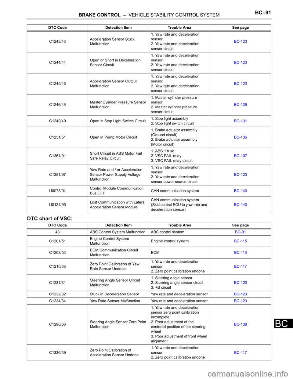
DTC chart of VSC:
C1243/43Acceleration Sensor Stuck
Malfunction1. Yaw rate and deceleration
sensor
2. Yaw rate and deceleration
sensor circuitBC-123
C1244/44Open or Short in Deceleration
Sensor Circuit1. Yaw rate and deceleration
sensor
2. Yaw rate and deceleration
sensor circuitBC-123
C1245/45Acceleration Sensor Output
Malfunction1. Yaw rate and deceleration
sensor
2. Yaw rate and deceleration
sensor circuitBC-123
C1246/46Master Cylinder Pressure Sensor
Malfunction1. Master cylinder pressure
sensor
2. Master cylinder pressure
sensor circuitBC-129
C1249/49 Open in Stop Light Switch Circuit1. Stop light assembly
2. Stop light switch circuitBC-131
C1251/51 Open in Pump Motor Circuit1. Brake actuator assembly
(Ground circuit)
2. Brake actuator assembly
(Motor circuit)BC-136
C1361/91Short Circuit in ABS Motor Fail
Safe Relay Circuit1. ABS 1 fuse
2. VSC FAIL relay
3. VSC FAIL relay circuitBC-107
C1381/97Yaw Rate and / or Acceleration
Sensor Power Supply Voltage
Malfunction1. Yaw rate and deceleration
sensor
2. Yaw rate and deceleration
sensor power source circuitBC-123
U0073/94Control Module Communication
Bus OFFCAN communication systemBC-140
U0124/95Lost Communication with Lateral
Acceleration Sensor ModuleCAN communication system
(Skid control ECU to yaw rate and
deceleration sensor)BC-140
DTC Code Detection Item Trouble Area See page
43 ABS Control System Malfunction ABS control systemBC-91
C1201/51Engine Control System
MalfunctionEngine control systemBC-115
C1203/53ECM Communication Circuit
MalfunctionECMBC-116
C1210/36Zero Point Calibration of Yaw
Rate Sensor Undone1. Yaw rate and deceleration
sensor
2. Zero point calibration undoneBC-117
C1231/31Steering Angle Sensor Circuit
Malfunction1. Steering angle sensor
2. Steering angle sensor circuit
3. +B circuitBC-120
C1232/32 Stuck in Deceleration Sensor Yaw rate and deceleration sensorBC-123
C1234/34 Yaw Rate Sensor Malfunction Yaw rate and deceleration sensorBC-123
C1290/66Steering Angle Sensor Zero Point
Malfunction1. Yaw rate and deceleration
sensor zero point calibration
incomplete
2. Poor adjustment of the
centered position of the steering
wheel
3. Poor adjustment of front wheel
alignmentBC-138
C1336/39Zero Point Calibration of
Acceleration Sensor Undone1. Yaw rate and deceleration
sensor
2. Zero point calibration undoneBC-117 DTC Code Detection Item Trouble Area See page
Page 2460 of 3000
BC–98BRAKE CONTROL – VEHICLE STABILITY CONTROL SYSTEM
BC
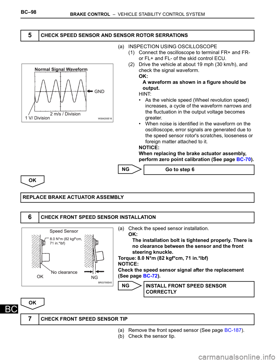
(a) INSPECTION USING OSCILLOSCOPE
(1) Connect the oscilloscope to terminal FR+ and FR-
or FL+ and FL- of the skid control ECU.
(2) Drive the vehicle at about 19 mph (30 km/h), and
check the signal waveform.
OK:
A waveform as shown in a figure should be
output.
HINT:
• As the vehicle speed (Wheel revolution speed)
increases, a cycle of the waveform narrows and
the fluctuation in the output voltage becomes
greater.
• When noise is identified in the waveform on the
oscilloscope, error signals are generated due to
the speed sensor rotor's scratches, looseness or
foreign matter attached to it.
NOTICE:
When replacing the brake actuator assembly,
perform zero point calibration (See page BC-70).
NG
OK
(a) Check the speed sensor installation.
OK:
The installation bolt is tightened properly. There is
no clearance between the sensor and the front
steering knuckle.
Torque: 8.0 N*m (82 kgf*cm, 71 in.*lbf)
NOTICE:
Check the speed sensor signal after the replacement
(See page BC-72).
NG
OK
(a) Remove the front speed sensor (See page BC-187).
(b) Check the sensor tip.
5CHECK SPEED SENSOR AND SENSOR ROTOR SERRATIONS
W004200E18
Go to step 6
REPLACE BRAKE ACTUATOR ASSEMBLY
6CHECK FRONT SPEED SENSOR INSTALLATION
BR03795E45INSTALL FRONT SPEED SENSOR
CORRECTLY
7CHECK FRONT SPEED SENSOR TIP
Page 2486 of 3000
BC–124BRAKE CONTROL – VEHICLE STABILITY CONTROL SYSTEM
BC
• When the speed sensor or the yaw rate sensor has trouble. DTCs for the steering angle sensor may be
output even when the steering angle sensor is normal. When DTCs for the speed sensor or yaw rate
sensor are output accompanied with other DTCs for the steering angle sensor, inspect and repair the
speed sensor and yaw rate sensor first, and the n inspect and repair the steering angle sensor.
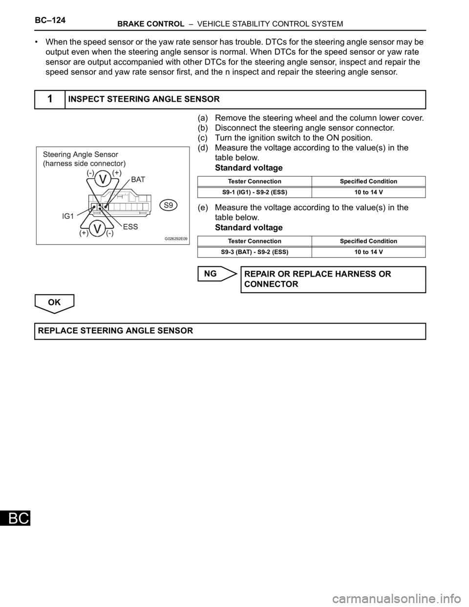
(a) Remove the steering wheel and the column lower cover.
(b) Disconnect the steering angle sensor connector.
(c) Turn the ignition switch to the ON position.
(d) Measure the voltage according to the value(s) in the
table below.
Standard voltage
(e) Measure the voltage according to the value(s) in the
table below.
Standard voltage
NG
OK
1INSPECT STEERING ANGLE SENSOR
G026292E09
Tester Connection Specified Condition
S9-1 (IG1) - S9-2 (ESS) 10 to 14 V
Tester Connection Specified Condition
S9-3 (BAT) - S9-2 (ESS) 10 to 14 V
REPAIR OR REPLACE HARNESS OR
CONNECTOR
REPLACE STEERING ANGLE SENSOR
Page 2502 of 3000
BC–140BRAKE CONTROL – VEHICLE STABILITY CONTROL SYSTEM
BC
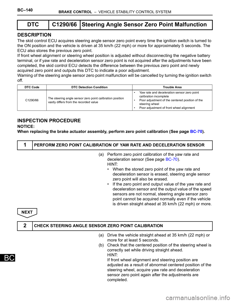
DESCRIPTION
The skid control ECU acquires steering angle sensor zero point every time the ignition switch is turned to
the ON position and the vehicle is driven at 35 km/h (22 mph) or more for approximately 5 seconds. The
ECU also stores the previous zero point.
If front wheel alignment or steering wheel position is adjusted without disconnecting the negative battery
terminal, or if yaw rate and deceleration sensor zero point is not acquired after the adjustments have been
completed, the skid control ECU detects the difference between the previous zero point and newly
acquired zero point and outputs this DTC to indicate a poor adjustment.
Warning of the steering angle sensor zero point malfunction will be cancelled by turning the ignition switch
off.
INSPECTION PROCEDURE
NOTICE:
When replacing the brake actuator assembly, perform zero point calibration (See page BC-70).
(a) Perform zero point calibration of the yaw rate and
deceleration sensor (See page BC-70).
HINT:
• When the stored zero point of the yaw rate and
deceleration sensor is erased, steering angle sensor
zero point will also be erased.
• If the zero point and output value of the yaw rate and
deceleration sensor and the output value of the speed
sensors are not normal, steering angle sensor zero
point cannot be acquired normally even if the vehicle
is driven straight ahead at 35 km/h (22 mph) or more.
NEXT
(a) Drive the vehicle straight ahead at 35 km/h (22 mph) or
more for at least 5 seconds.
(b) Check that the centered position of the steering wheel is
correctly set while driving straight ahead.
HINT:
If front wheel alignment and steering position are
adjusted as a result of abnormal centered position of the
steering wheel, acquire yaw rate and deceleration
sensor zero point again after the adjustments are
completed.
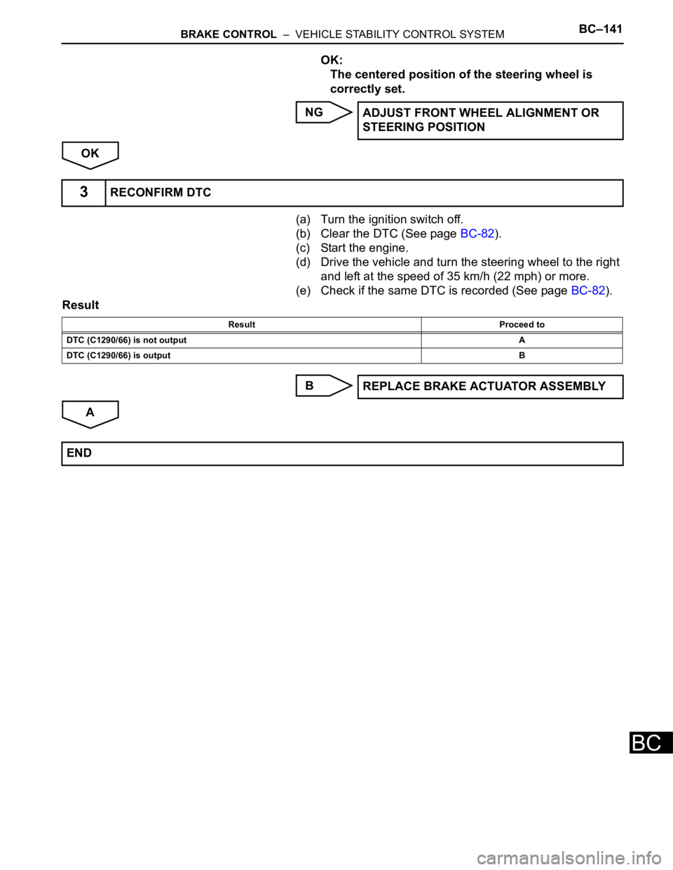
DTC C1290/66 Steering Angle Sensor Zero Point Malfunction
DTC Code DTC Detection Condition Trouble Area
C1290/66The steering angle sensor zero point calibration position
vastly differs from the recorded value• Yaw rate and deceleration sensor zero point
calibration incomplete
• Poor adjustment of the centered position of the
steering wheel
• Poor adjustment of front wheel alignment
1PERFORM ZERO POINT CALIBRATION OF YAW RATE AND DECELERATION SENSOR
2CHECK STEERING ANGLE SENSOR ZERO POINT CALIBRATION
Page 2503 of 3000
BRAKE CONTROL – VEHICLE STABILITY CONTROL SYSTEMBC–141
BC
OK:
The centered position of the steering wheel is
correctly set.
NG
OK
(a) Turn the ignition switch off.
(b) Clear the DTC (See page BC-82).
(c) Start the engine.
(d) Drive the vehicle and turn the steering wheel to the right
and left at the speed of 35 km/h (22 mph) or more.
(e) Check if the same DTC is recorded (See page BC-82).
Result
B
AADJUST FRONT WHEEL ALIGNMENT OR
STEERING POSITION
3RECONFIRM DTC
Result Proceed to
DTC (C1290/66) is not outputA
DTC (C1290/66) is outputB
REPLACE BRAKE ACTUATOR ASSEMBLY
END
Page 2550 of 3000
BRAKE CONTROL – ANTI-LOCK BRAKE SYSTEMBC–21
BC
(b) Check that there is the speed value output from the
speed sensor displayed on the intelligent tester and the
speed value displayed on the speedometer are almost
the same when driving the vehicle.
OK:
The speed value output from the speed sensor
displayed on the intelligent tester is the same as
the actual vehicle speed.
NG
OK
(a) Clear the DTC (See page BC-10).
(b) Perform sensor signal check in TEST MODE
PROCEDURE (See page BC-3).
OK:
All Test Mode DTCs are erased.
OK
NG
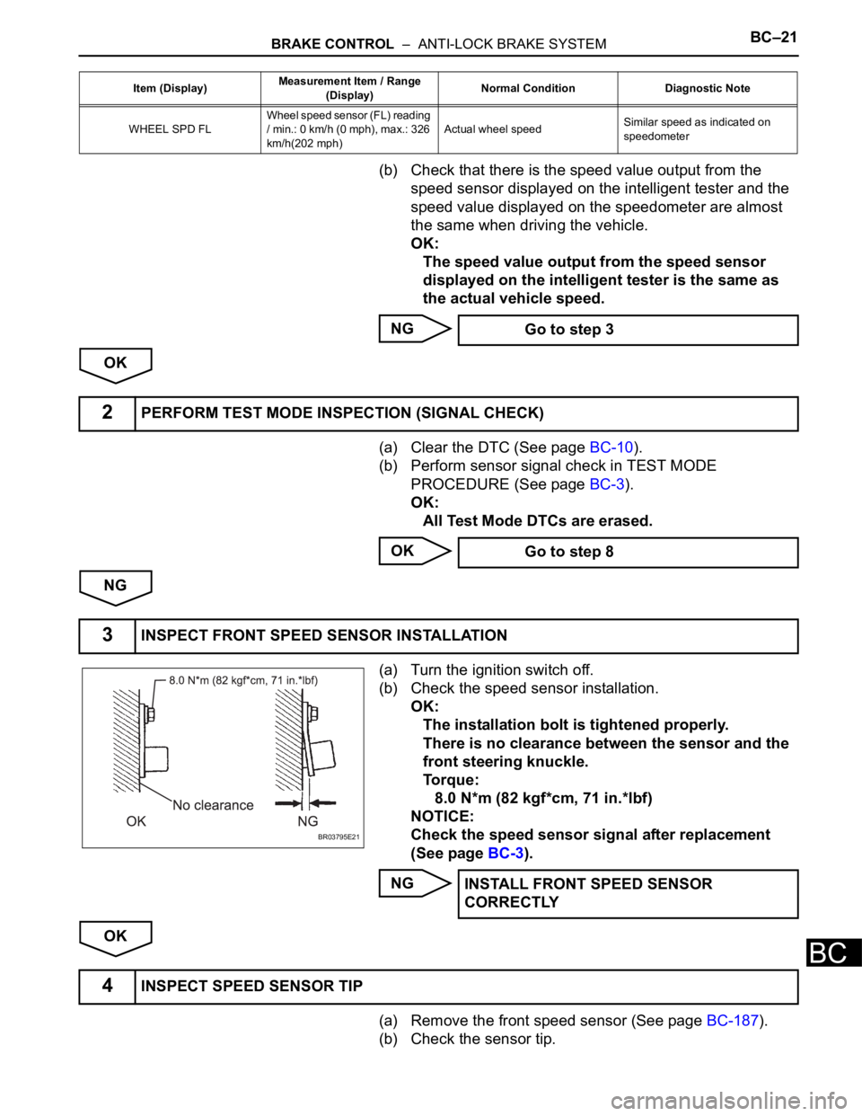
(a) Turn the ignition switch off.
(b) Check the speed sensor installation.
OK:
The installation bolt is tightened properly.
There is no clearance between the sensor and the
front steering knuckle.
To r q u e :
8.0 N*m (82 kgf*cm, 71 in.*lbf)
NOTICE:
Check the speed sensor signal after replacement
(See page BC-3).
NG
OK
(a) Remove the front speed sensor (See page BC-187).
(b) Check the sensor tip.
WHEEL SPD FLWheel speed sensor (FL) reading
/ min.: 0 km/h (0 mph), max.: 326
km/h(202 mph)Actual wheel speedSimilar speed as indicated on
speedometer Item (Display)Measurement Item / Range
(Display)Normal Condition Diagnostic Note
Go to step 3
2PERFORM TEST MODE INSPECTION (SIGNAL CHECK)
Go to step 8
3INSPECT FRONT SPEED SENSOR INSTALLATION
BR03795E21
INSTALL FRONT SPEED SENSOR
CORRECTLY
4INSPECT SPEED SENSOR TIP