2007 TOYOTA SIENNA relay
[x] Cancel search: relayPage 2886 of 3000
AIR CONDITIONING – AIR CONDITIONING SYSTEM (for Automatic Air Conditioning Sys-
tem)AC–143
AC
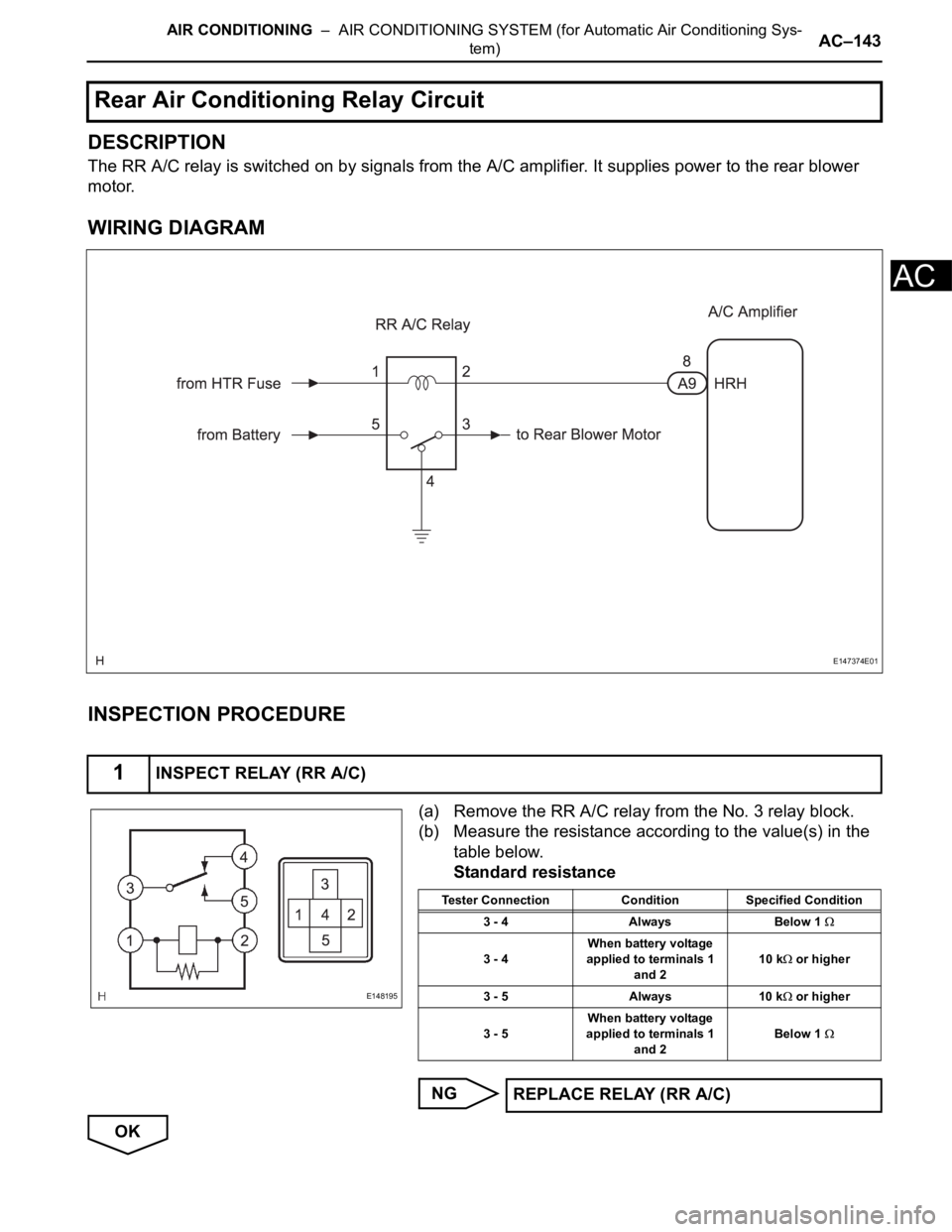
DESCRIPTION
The RR A/C relay is switched on by signals from the A/C amplifier. It supplies power to the rear blower
motor.
WIRING DIAGRAM
INSPECTION PROCEDURE
(a) Remove the RR A/C relay from the No. 3 relay block.
(b) Measure the resistance according to the value(s) in the
table below.
Standard resistance
NG
OK
Rear Air Conditioning Relay Circuit
1INSPECT RELAY (RR A/C)
E147374E01
E148195
Tester Connection Condition Specified Condition
3 - 4 Always Below 1
3 - 4When battery voltage
applied to terminals 1
and 210 k or higher
3 - 5 Always 10 k
or higher
3 - 5When battery voltage
applied to terminals 1
and 2Below 1
REPLACE RELAY (RR A/C)
Page 2888 of 3000
AIR CONDITIONING – AIR CONDITIONING SYSTEM (for Automatic Air Conditioning Sys-
tem)AC–145
AC
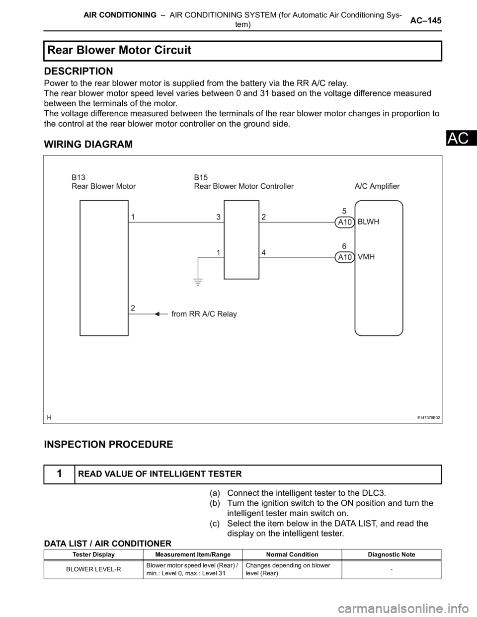
DESCRIPTION
Power to the rear blower motor is supplied from the battery via the RR A/C relay.
The rear blower motor speed level varies between 0 and 31 based on the voltage difference measured
between the terminals of the motor.
The voltage difference measured between the terminals of the rear blower motor changes in proportion to
the control at the rear blower motor controller on the ground side.
WIRING DIAGRAM
INSPECTION PROCEDURE
(a) Connect the intelligent tester to the DLC3.
(b) Turn the ignition switch to the ON position and turn the
intelligent tester main switch on.
(c) Select the item below in the DATA LIST, and read the
display on the intelligent tester.
DATA LIST / AIR CONDITIONER
Rear Blower Motor Circuit
1READ VALUE OF INTELLIGENT TESTER
E147375E02
Tester Display Measurement Item/Range Normal Condition Diagnostic Note
BLOWER LEVEL-RBlower motor speed level (Rear) /
min.: Level 0, max.: Level 31Changes depending on blower
level (Rear)-
Page 2893 of 3000
AC–150AIR CONDITIONING – AIR CONDITIONING SYSTEM (for Automatic Air Conditioning Sys-
tem)
AC
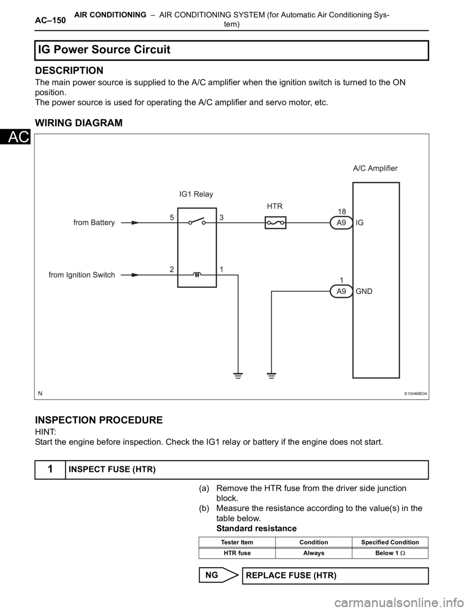
DESCRIPTION
The main power source is supplied to the A/C amplifier when the ignition switch is turned to the ON
position.
The power source is used for operating the A/C amplifier and servo motor, etc.
WIRING DIAGRAM
INSPECTION PROCEDURE
HINT:
Start the engine before inspection. Check the IG1 relay or battery if the engine does not start.
(a) Remove the HTR fuse from the driver side junction
block.
(b) Measure the resistance according to the value(s) in the
table below.
Standard resistance
NG
IG Power Source Circuit
1INSPECT FUSE (HTR)
E130466E04
Tester Item Condition Specified Condition
HTR fuse Always Below 1
REPLACE FUSE (HTR)
Page 2896 of 3000
AIR CONDITIONING – AIR CONDITIONING SYSTEM (for Automatic Air Conditioning Sys-
tem)AC–153
AC
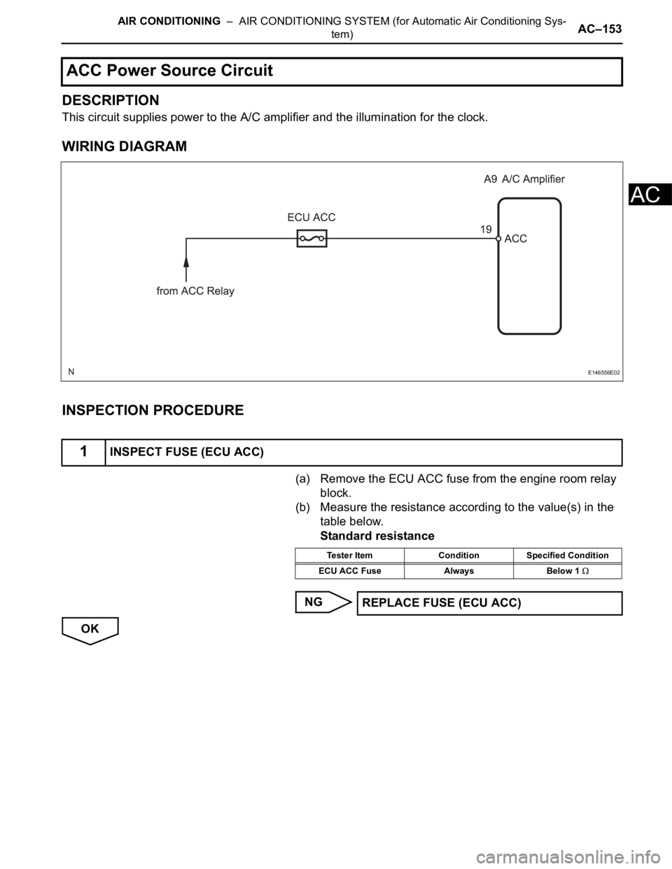
DESCRIPTION
This circuit supplies power to the A/C amplifier and the illumination for the clock.
WIRING DIAGRAM
INSPECTION PROCEDURE
(a) Remove the ECU ACC fuse from the engine room relay
block.
(b) Measure the resistance according to the value(s) in the
table below.
Standard resistance
NG
OK
ACC Power Source Circuit
1INSPECT FUSE (ECU ACC)
E146556E02
Tester Item Condition Specified Condition
ECU ACC Fuse Always Below 1
REPLACE FUSE (ECU ACC)
Page 2900 of 3000
AIR CONDITIONING – AIR CONDITIONING SYSTEM (for Automatic Air Conditioning Sys-
tem)AC–11
AC
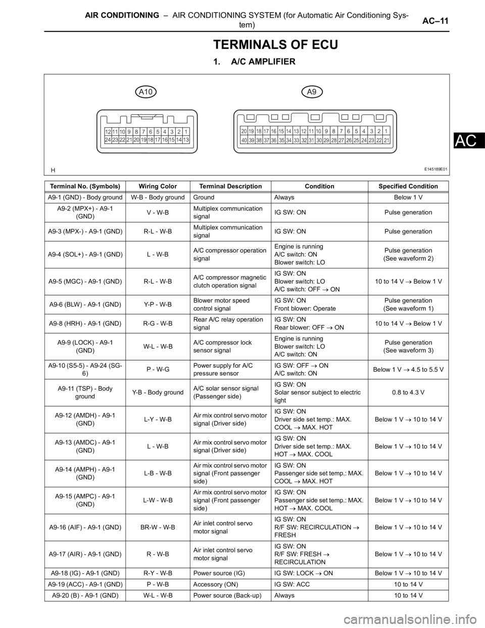
TERMINALS OF ECU
1. A/C AMPLIFIER
Terminal No. (Symbols) Wiring Color Terminal Description ConditionSpecified Condition
A9-1 (GND) - Body ground W-B - Body ground Ground Always Below 1 V
A9-2 (MPX+) - A9-1
(GND)V - W-BMultiplex communication
signalIG SW: ON Pulse generation
A9-3 (MPX-) - A9-1 (GND) R-L - W-BMultiplex communication
signalIG SW: ON Pulse generation
A9-4 (SOL+) - A9-1 (GND) L - W-BA/C compressor operation
signalEngine is running
A/C switch: ON
Blower switch: LOPulse generation
(See waveform 2)
A9-5 (MGC) - A9-1 (GND) R-L - W-BA/C compressor magnetic
clutch operation signalIG SW: ON
Blower switch: LO
A/C switch: OFF
ON10 to 14 V Below 1 V
A9-6 (BLW) - A9-1 (GND) Y-P - W-BBlower motor speed
control signalIG SW: ON
Front blower: OperatePulse generation
(See waveform 1)
A9-8 (HRH) - A9-1 (GND) R-G - W-BRear A/C relay operation
signalIG SW: ON
Rear blower: OFF
ON10 to 14 V Below 1 V
A9-9 (LOCK) - A9-1
(GND)W-L - W-BA/C compressor lock
sensor signalEngine is running
Blower switch: LO
A/C switch: ONPulse generation
(See waveform 3)
A9-10 (S5-5) - A9-24 (SG-
6)P - W-GPower supply for A/C
pressure sensorIG SW: OFF
ON
A/C switch: ONBelow 1 V 4.5 to 5.5 V
A9-11 (TSP) - Body
groundY-B - Body groundA/C solar sensor signal
(Passenger side)IG SW: ON
Solar sensor subject to electric
light0.8 to 4.3 V
A9-12 (AMDH) - A9-1
(GND)L-Y - W-BAir mix control servo motor
signal (Driver side)IG SW: ON
Driver side set temp.: MAX.
COOL
MAX. HOTBelow 1 V
10 to 14 V
A9-13 (AMDC) - A9-1
(GND)L - W-BAir mix control servo motor
signal (Driver side)IG SW: ON
Driver side set temp.: MAX.
HOT
MAX. COOLBelow 1 V 10 to 14 V
A9-14 (AMPH) - A9-1
(GND)L-B - W-BAir mix control servo motor
signal (Front passenger
side)IG SW: ON
Passenger side set temp.: MAX.
COOL
MAX. HOTBelow 1 V
10 to 14 V
A9-15 (AMPC) - A9-1
(GND)L-W - W-BAir mix control servo motor
signal (Front passenger
side)IG SW: ON
Passenger side set temp.: MAX.
HOT
MAX. COOLBelow 1 V
10 to 14 V
A9-16 (AIF) - A9-1 (GND) BR-W - W-BAir inlet control servo
motor signalIG SW: ON
R/F SW: RECIRCULATION
FRESHBelow 1 V 10 to 14 V
A9-17 (AIR) - A9-1 (GND) R - W-BAir inlet control servo
motor signalIG SW: ON
R/F SW: FRESH
RECIRCULATIONBelow 1 V 10 to 14 V
A9-18 (IG) - A9-1 (GND) R-Y - W-B Power source (IG) IG SW: LOCK
ON Below 1 V 10 to 14 V
A9-19 (ACC) - A9-1 (GND) P - W-B Accessory (ON) IG SW: ACC 10 to 14 V
A9-20 (B) - A9-1 (GND) W-L - W-B Power source (Back-up) Always 10 to 14 V
E145189E01
Page 2902 of 3000
AIR CONDITIONING – AIR CONDITIONING SYSTEM (for Automatic Air Conditioning Sys-
tem)AC–13
AC
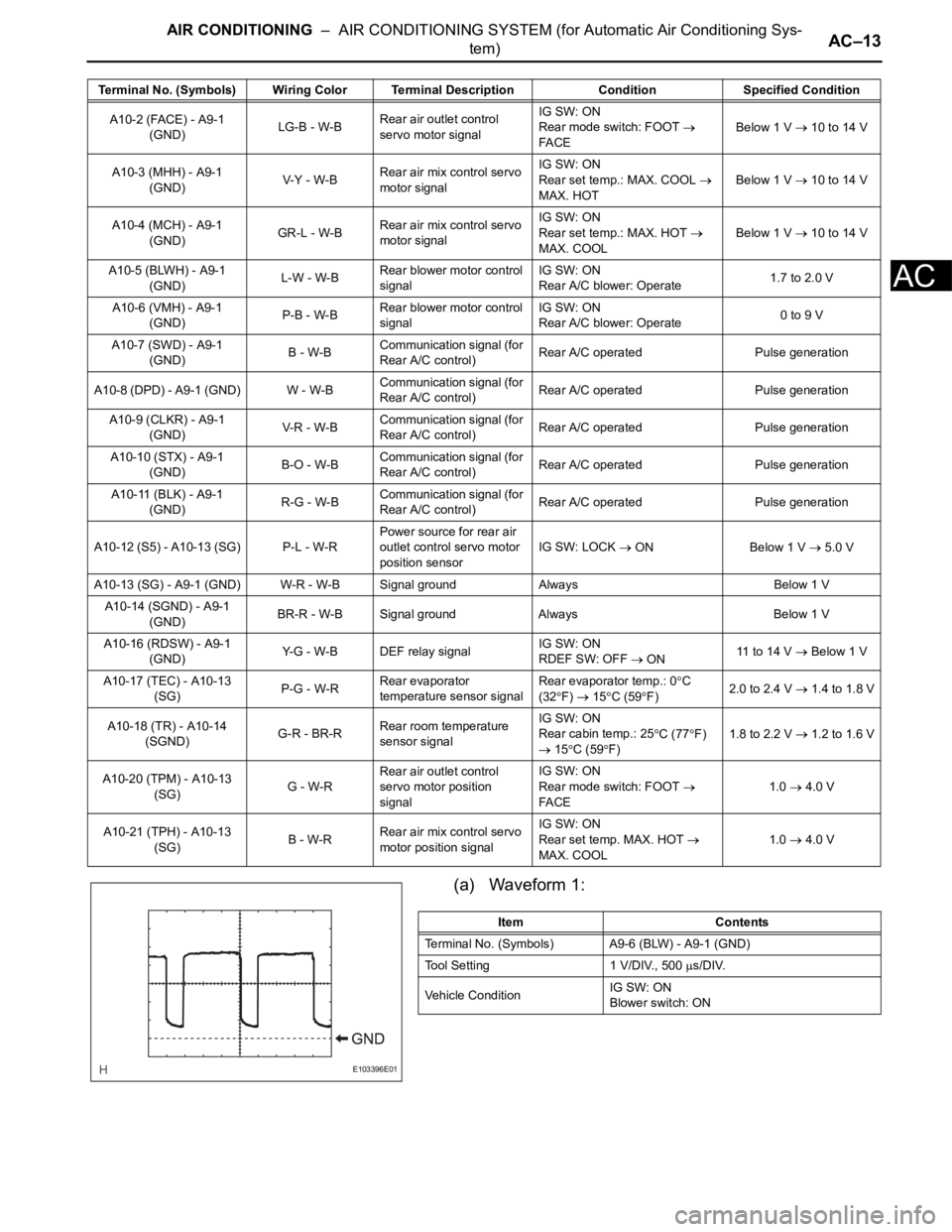
(a) Waveform 1:
A10-2 (FACE) - A9-1
(GND)LG-B - W-BRear air outlet control
servo motor signalIG SW: ON
Rear mode switch: FOOT
FA C EBelow 1 V 10 to 14 V
A10-3 (MHH) - A9-1
(GND)V-Y - W-BRear air mix control servo
motor signalIG SW: ON
Rear set temp.: MAX. COOL
MAX. HOTBelow 1 V 10 to 14 V
A10-4 (MCH) - A9-1
(GND)GR-L - W-BRear air mix control servo
motor signalIG SW: ON
Rear set temp.: MAX. HOT
MAX. COOLBelow 1 V 10 to 14 V
A10-5 (BLWH) - A9-1
(GND)L-W - W-BRear blower motor control
signalIG SW: ON
Rear A/C blower: Operate1.7 to 2.0 V
A10-6 (VMH) - A9-1
(GND)P-B - W-BRear blower motor control
signalIG SW: ON
Rear A/C blower: Operate0 to 9 V
A10-7 (SWD) - A9-1
(GND)B - W-BCommunication signal (for
Rear A/C control)Rear A/C operated Pulse generation
A10-8 (DPD) - A9-1 (GND) W - W-BCommunication signal (for
Rear A/C control)Rear A/C operated Pulse generation
A10-9 (CLKR) - A9-1
(GND)V-R - W- BCommunication signal (for
Rear A/C control)Rear A/C operated Pulse generation
A10-10 (STX) - A9-1
(GND)B-O - W-BCommunication signal (for
Rear A/C control)Rear A/C operated Pulse generation
A10-11 (BLK) - A9-1
(GND)R-G - W-BCommunication signal (for
Rear A/C control)Rear A/C operated Pulse generation
A10-12 (S5) - A10-13 (SG) P-L - W-RPower source for rear air
outlet control servo motor
position sensorIG SW: LOCK
ON Below 1 V 5.0 V
A10-13 (SG) - A9-1 (GND) W-R - W-B Signal ground Always Below 1 V
A10-14 (SGND) - A9-1
(GND)BR-R - W-B Signal ground Always Below 1 V
A10-16 (RDSW) - A9-1
(GND)Y-G - W-B DEF relay signalIG SW: ON
RDEF SW: OFF
ON11 to 14 V Below 1 V
A10-17 (TEC) - A10-13
(SG)P-G - W-RRear evaporator
temperature sensor signalRear evaporator temp.: 0
C
(32
F) 15C (59F)2.0 to 2.4 V 1.4 to 1.8 V
A10-18 (TR) - A10-14
(SGND)G-R - BR-RRear room temperature
sensor signalIG SW: ON
Rear cabin temp.: 25
C (77F)
15C (59F)1.8 to 2.2 V
1.2 to 1.6 V
A10-20 (TPM) - A10-13
(SG)G - W-RRear air outlet control
servo motor position
signalIG SW: ON
Rear mode switch: FOOT
FA C E1.0 4.0 V
A10-21 (TPH) - A10-13
(SG)B - W-RRear air mix control servo
motor position signalIG SW: ON
Rear set temp. MAX. HOT
MAX. COOL1.0 4.0 V Terminal No. (Symbols) Wiring Color Terminal Description ConditionSpecified Condition
E103396E01
Item Contents
Terminal No. (Symbols) A9-6 (BLW) - A9-1 (GND)
Tool Setting 1 V/DIV., 500
s/DIV.
Vehicle ConditionIG SW: ON
Blower switch: ON
Page 2908 of 3000
AIR CONDITIONING – AIR CONDITIONING SYSTEM (for Manual Air Conditioning System)AC–167
AC
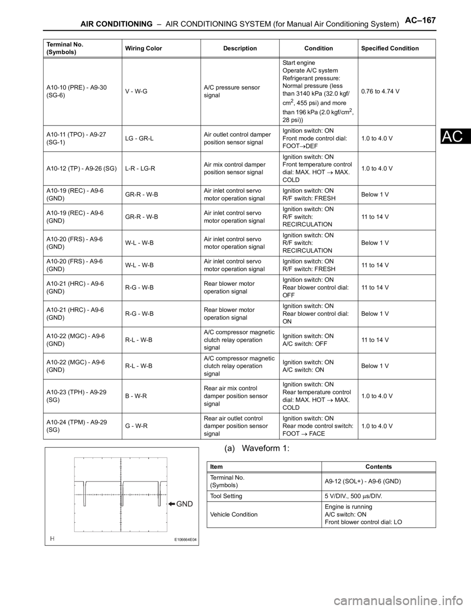
(a) Waveform 1:
A10-10 (PRE) - A9-30
(SG-6)V - W-GA/C pressure sensor
signalStart engine
Operate A/C system
Refrigerant pressure:
Normal pressure (less
than 3140 kPa (32.0 kgf/
cm
2, 455 psi) and more
than 196 kPa (2.0 kgf/cm2,
28 psi))0.76 to 4.74 V
A10-11 (TPO) - A9-27
(SG-1)LG - GR-LAir outlet control damper
position sensor signalIgnition switch: ON
Front mode control dial:
FOOT
DEF1.0 to 4.0 V
A10-12 (TP) - A9-26 (SG) L-R - LG-RAir mix control damper
position sensor signalIgnition switch: ON
Front temperature control
dial: MAX. HOT
MAX.
COLD1.0 to 4.0 V
A10-19 (REC) - A9-6
(GND)GR-R - W-BAir inlet control servo
motor operation signalIgnition switch: ON
R/F switch: FRESHBelow 1 V
A10-19 (REC) - A9-6
(GND)GR-R - W-BAir inlet control servo
motor operation signalIgnition switch: ON
R/F switch:
RECIRCULATION11 to 14 V
A10-20 (FRS) - A9-6
(GND)W-L - W-BAir inlet control servo
motor operation signalIgnition switch: ON
R/F switch:
RECIRCULATIONBelow 1 V
A10-20 (FRS) - A9-6
(GND)W-L - W-BAir inlet control servo
motor operation signalIgnition switch: ON
R/F switch: FRESH11 to 14 V
A10-21 (HRC) - A9-6
(GND)R-G - W-BRear blower motor
operation signalIgnition switch: ON
Rear blower control dial:
OFF11 to 14 V
A10-21 (HRC) - A9-6
(GND)R-G - W-BRear blower motor
operation signalIgnition switch: ON
Rear blower control dial:
ONBelow 1 V
A10-22 (MGC) - A9-6
(GND)R-L - W-BA/C compressor magnetic
clutch relay operation
signalIgnition switch: ON
A/C switch: OFF11 t o 1 4 V
A10-22 (MGC) - A9-6
(GND)R-L - W-BA/C compressor magnetic
clutch relay operation
signalIgnition switch: ON
A/C switch: ONBelow 1 V
A10-23 (TPH) - A9-29
(SG)B - W-RRear air mix control
damper position sensor
signalIgnition switch: ON
Rear temperature control
dial: MAX. HOT
MAX.
COLD1.0 to 4.0 V
A10-24 (TPM) - A9-29
(SG)G - W-RRear air outlet control
damper position sensor
signalIgnition switch: ON
Rear mode control switch:
FOOT
FACE1.0 to 4.0 V Terminal No.
(Symbols)Wiring Color Description Condition Specified Condition
E106664E04
Item Contents
Terminal No.
(Symbols)A9-12 (SOL+) - A9-6 (GND)
Tool Setting 5 V/DIV., 500
s/DIV.
Vehicle ConditionEngine is running
A/C switch: ON
Front blower control dial: LO
Page 2919 of 3000

AIR CONDITIONING – AIR CONDITIONING SYSTEM (for Automatic Air Conditioning Sys-
tem)AC–19
AC
HINT:
*1: It differs depending on the user setting.
2. ACTIVE TEST
HINT:
Using the intelligent tester to perform Active Tests allows
relays, VSVs, actuators and other items to be operated
without removing any parts. This non-intrusive functional
inspection can be very useful because intermittent
operation may be discovered before parts or wiring is
disturbed. Performing Active Tests early in
troubleshooting is one way to save diagnostic time. Data
List information can be displayed while performing Active
Tests.
(a) Connect the intelligent tester to the DLC3.
A/I DAMP TARGAir inlet damper target position /
min.: -14%, max.: 113.5%Changes depending on air inlet
damper position-
A/O DAMP TARGAir outlet damper target position /
min.: -14%, max.: 113.5%Changes depending on air outlet
damper position-
BLOWER LEVELBlower motor speed level / min.:
Level 0, max.: Level 31Changes depending on blower
level-
REAR ROOM TEMPRoom temperature sensor (Rear)
/ min.: -6.5
C (20.3F), max.:
57.25C (135.05F)Actual cabin temperature (Rear) -
R-EVAP TEMP SENRr. EVAP temperature sensor
(Rear) / min.: -29.7
C (-21.46F),
max.: 59.55
C (139.19F)Actual evaporator temperature
(Rear)-
SET TEMP REARSet temperature (Rear) / min.: 0,
max. 255Actual set temperature -
ESTIMATE TEMP-REstimated temperature (Rear) /
min.: -358.4
C (-613.12F), max.:
358.4
C (677.12F)--
A/M DAMP POS-RAir mix damper position (Rear) /
min.: -14%, max.: 113.5%Changes depending on the set
temperature (Rear)-
A/O DAMP POS-RAir outlet mode damper position
(Rear) / min.: -14%, max.: 113.5%Changes depending on air outlet
damper position (Rear)-
A/M DAMP TARG-RAir mix damper target position
(Rear) / min.: -14%, max.: 113.5%Changes depending on the set
temperature (Rear)-
A/O DAMP TARG-RAir outlet damper target position
(Rear) / min.: -14%, max.: 113.5%Changes depending on air outlet
damper position (Rear)-
BLOWER LEVEL-RBlower motor speed level (Rear) /
min.: Level 0, max: Level 31Changes depending on blower
level (Rear)-
SET TEMP SHIFT Shift set temperatureChanges depending on shift set
temperature *1-
AIR INLET MODE Air inlet modeChanges depending on air inlet
mode *1-
COMPRESSOR MODE Compressor modeChanges depending on
compressor mode *1-
COMPRS/DEF MODE Compressor/DEF operation modeChanges depending on
compressor/DEF operation mode
*1-
FOOT/DEF OPER Foot/DEF auto modeChanges depending on Foot/DEF
auto mode *1-
AUTO BLOW UPFoot/DEF automatic blow up
functionChanges depending on Foot/DEF
automatic blow up function *1-
#CODESNumber of Trouble Codes / min.:
0, max.: 255-- Tester Display Measurement Item/Range Normal Condition Diagnostic Note