2007 TOYOTA SIENNA relay
[x] Cancel search: relayPage 2582 of 3000

BRAKE CONTROL – ANTI-LOCK BRAKE SYSTEMBC–39
BC
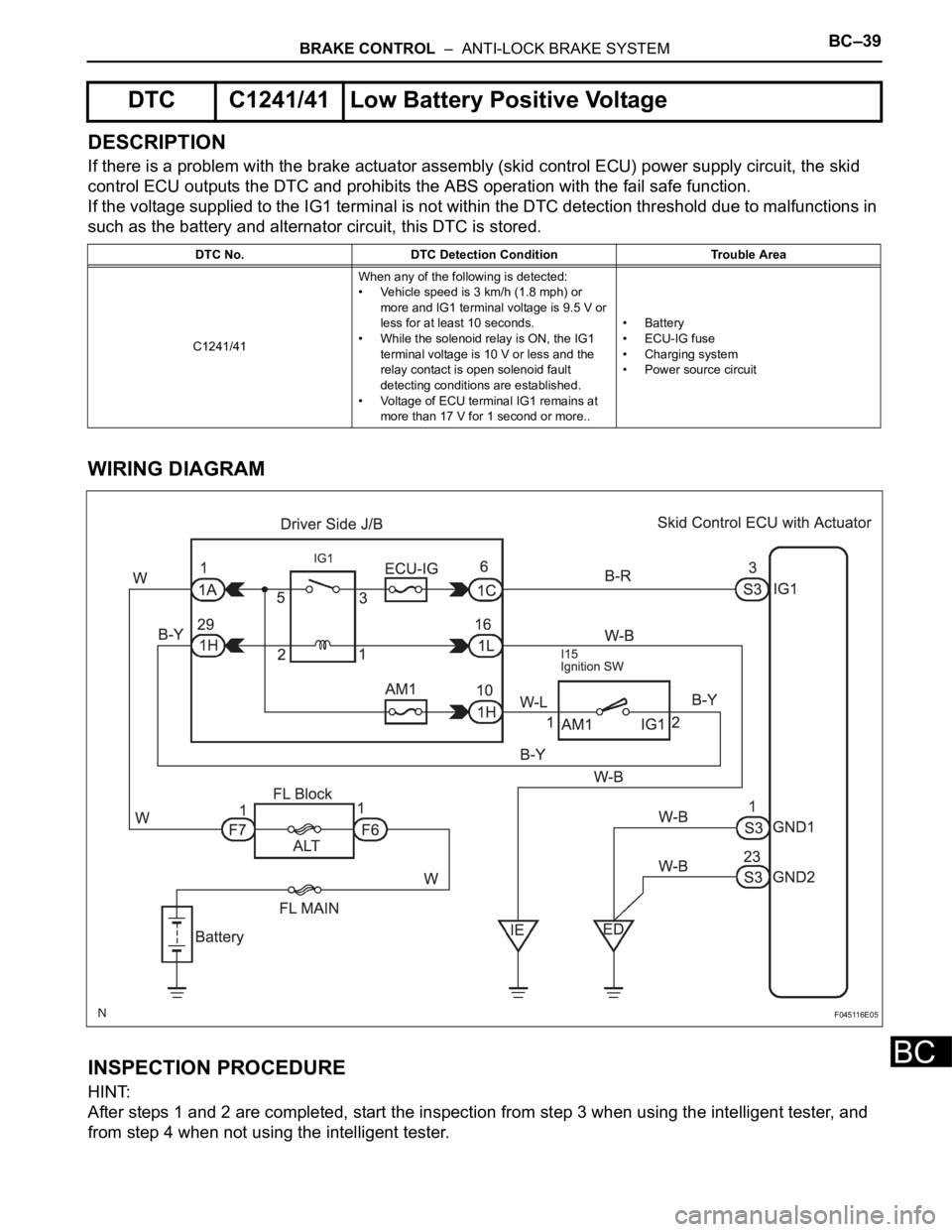
DESCRIPTION
If there is a problem with the brake actuator assembly (skid control ECU) power supply circuit, the skid
control ECU outputs the DTC and prohibits the ABS operation with the fail safe function.
If the voltage supplied to the IG1 terminal is not within the DTC detection threshold due to malfunctions in
such as the battery and alternator circuit, this DTC is stored.
WIRING DIAGRAM
INSPECTION PROCEDURE
HINT:
After steps 1 and 2 are completed, start the inspection from step 3 when using the intelligent tester, and
from step 4 when not using the intelligent tester.
DTC C1241/41 Low Battery Positive Voltage
DTC No. DTC Detection Condition Trouble Area
C1241/41When any of the following is detected:
• Vehicle speed is 3 km/h (1.8 mph) or
more and IG1 terminal voltage is 9.5 V or
less for at least 10 seconds.
• While the solenoid relay is ON, the IG1
terminal voltage is 10 V or less and the
relay contact is open solenoid fault
detecting conditions are established.
• Voltage of ECU terminal IG1 remains at
more than 17 V for 1 second or more..• Battery
•ECU-IG fuse
• Charging system
• Power source circuit
F045116E05
Page 2757 of 3000

AIR CONDITIONING – AIR CONDITIONING SYSTEM (for Automatic Air Conditioning Sys-
tem)AC–9
AC
Rear A/C:
No air inlet controlAir inlet damper control servo motor circuitAC-98
Air inlet damper position sensor circuitAC-73
A/C amplifierAC-253
No air outlet controlAir outlet damper position sensor circuitAC-77
Air outlet control servo motor circuitAC-103
A/C amplifierAC-253
Engine idle up does not occur, or is continuousCompressor circuitAC-134
A/C amplifierAC-253
Displayed set temperature value does not match up
with operation of temperature control switchA/C amplifierAC-253
Brightness does not change when rheostat volume or
light control switch is turnedA/C amplifierAC-253
Unable to access the diagnosis mode A/C amplifierAC-253
DTC is not recorded. Set mode is cleared when IG
switch is turned offBack-up power source circuitAC-154
A/C amplifierAC-253
Symptom Suspected Area See page
Whole functions of the A/C system do not operateA/C amplifierAC-253
Rear air conditioning relay circuitAC-142
Rear air conditioning control panel circuitAC-139
Air Flow Control: No blower operationRear blower motor circuitAC-144
A/C amplifierAC-253
Air Flow Control: No blower controlRear blower motor circuitAC-144
A/C amplifierAC-253
Air Flow Control: Insufficient air outRear blower motor circuitAC-144
A/C amplifierAC-253
Temperature Control: Cool air does not come outVolume of refrigerantAC-168
Drive belt tension -
Refrigerant pressureAC-168
Compressor circuitAC-134
Pressure sensor circuitAC-51
Ambient temperature sensor circuitAC-28
Rear evaporator temperature sensor circuitAC-35
A/C amplifierAC-253
Temperature Control: Warm air does not come outRear air mix control servo motor circuitAC-113
Rear air mix damper position sensor circuitAC-85
Ambient temperature sensor circuitAC-28
Rear room temperature sensor circuitAC-39
Rear evaporator temperature sensor circuitAC-35
A/C amplifierAC-253
Heater radiatorAC-187
Temperature Control: Output air is warmer or cooler
than the set temperature or response is slowRear room temperature sensor circuitAC-39
Ambient temperature sensor circuitAC-28
Rear air mix damper position sensor circuitAC-85
Rear air mix control servo motor circuitAC-113
A/C amplifierAC-253
Temperature Control: No temperature control (only
Max. cool or Max. hot)Rear air mix control servo motor circuitAC-113
Rear air mix damper position sensor circuitAC-85
A/C amplifierAC-253 Symptom Suspected Area See page
Page 2763 of 3000

AIR CONDITIONING – AIR CONDITIONING SYSTEM (for Automatic Air Conditioning Sys-
tem)AC–9
AC
Rear A/C:
No air inlet controlAir inlet damper control servo motor circuitAC-98
Air inlet damper position sensor circuitAC-73
A/C amplifierAC-253
No air outlet controlAir outlet damper position sensor circuitAC-77
Air outlet control servo motor circuitAC-103
A/C amplifierAC-253
Engine idle up does not occur, or is continuousCompressor circuitAC-134
A/C amplifierAC-253
Displayed set temperature value does not match up
with operation of temperature control switchA/C amplifierAC-253
Brightness does not change when rheostat volume or
light control switch is turnedA/C amplifierAC-253
Unable to access the diagnosis mode A/C amplifierAC-253
DTC is not recorded. Set mode is cleared when IG
switch is turned offBack-up power source circuitAC-154
A/C amplifierAC-253
Symptom Suspected Area See page
Whole functions of the A/C system do not operateA/C amplifierAC-253
Rear air conditioning relay circuitAC-142
Rear air conditioning control panel circuitAC-139
Air Flow Control: No blower operationRear blower motor circuitAC-144
A/C amplifierAC-253
Air Flow Control: No blower controlRear blower motor circuitAC-144
A/C amplifierAC-253
Air Flow Control: Insufficient air outRear blower motor circuitAC-144
A/C amplifierAC-253
Temperature Control: Cool air does not come outVolume of refrigerantAC-168
Drive belt tension -
Refrigerant pressureAC-168
Compressor circuitAC-134
Pressure sensor circuitAC-51
Ambient temperature sensor circuitAC-28
Rear evaporator temperature sensor circuitAC-35
A/C amplifierAC-253
Temperature Control: Warm air does not come outRear air mix control servo motor circuitAC-113
Rear air mix damper position sensor circuitAC-85
Ambient temperature sensor circuitAC-28
Rear room temperature sensor circuitAC-39
Rear evaporator temperature sensor circuitAC-35
A/C amplifierAC-253
Heater radiatorAC-187
Temperature Control: Output air is warmer or cooler
than the set temperature or response is slowRear room temperature sensor circuitAC-39
Ambient temperature sensor circuitAC-28
Rear air mix damper position sensor circuitAC-85
Rear air mix control servo motor circuitAC-113
A/C amplifierAC-253
Temperature Control: No temperature control (only
Max. cool or Max. hot)Rear air mix control servo motor circuitAC-113
Rear air mix damper position sensor circuitAC-85
A/C amplifierAC-253 Symptom Suspected Area See page
Page 2771 of 3000

AIR CONDITIONING – AIR CONDITIONING SYSTEM (for Automatic Air Conditioning Sys-
tem)AC–25
AC
(b) As each damper, motor and relay automatically
operate actuator check at 1-second intervals from
step No. 1 to No. 10 continuously, check the
temperature and air flow visually and by hand.
If the slower display is desired, press the DEF
switch and change it to step operation. Each time
the DEF switch is pressed, the display changes by 1
step.
HINT:
• Codes are displayed from smaller to larger
numbers in order.
• To cancel the check mode, press the OFF switch.
Step No.Display
codeConditions
Fr. Blower
levelFr. Air flow
ventAir inlet
damperMagnetic
clutchFr. Driver,
passenger
side air
mix
damperRr. Blower
levelRr. Air flow
ventRr. Air mix
damper
1 0 0 FACE FRESH OFF"COOL"
side
(Full
closed)0 FACE1"COOL"
side
(Full
closed)
2 1 1 FACE FRESH OFF"COOL"
side
(Full
closed)1 FACE1"COOL"
side
(Full
closed)
3 2 16 FACE FRESH ON"COOL"
side
(Full
closed)10 FACE1"COOL" /
"HOT"
(40% open)
4316FACEFRESH /
RECIRCUL
AT I O NON"COOL"
side
(Full
closed)10 FACE2"COOL" /
"HOT"
(40% open)
5416FACERECIRCUL
AT I O NON"COOL" /
"HOT"
(50% open)10 B/L"COOL" /
"HOT"
(40% open)
6516B/LRECIRCUL
AT I O NON"COOL" /
"HOT"
(50% open)10 B/L"COOL" /
"HOT"
(60% open)
7616FOOTRECIRCUL
AT I O NON"HOT" side
(Full open)10 B/L"COOL" /
"HOT"
(60% open)
8716FOOTRECIRCUL
AT I O NON
"HOT" side
(Full open)10 FOOT"COOL" /
"HOT"
(60% open)
9816FOOT /
DEF.RECIRCUL
AT I O NON"HOT" side
(Full open)10 FOOT"COOL" /
"HOT"
(86.5%
open)
10931DEF.RECIRCUL
AT I O NON"HOT" side
(Full open)31 FOOT"COOL" /
"HOT"
(86.5%
open)
Page 2878 of 3000

AIR CONDITIONING – AIR CONDITIONING SYSTEM (for Automatic Air Conditioning Sys-
tem)AC–135
AC
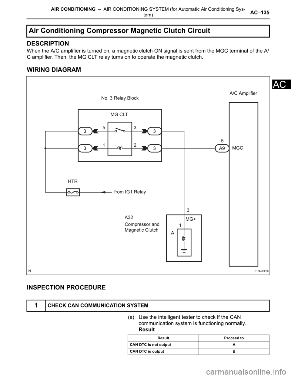
DESCRIPTION
When the A/C amplifier is turned on, a magnetic clutch ON signal is sent from the MGC terminal of the A/
C amplifier. Then, the MG CLT relay turns on to operate the magnetic clutch.
WIRING DIAGRAM
INSPECTION PROCEDURE
(a) Use the intelligent tester to check if the CAN
communication system is functioning normally.
Result
Air Conditioning Compressor Magnetic Clutch Circuit
1CHECK CAN COMMUNICATION SYSTEM
E124490E08
Result Proceed to
CAN DTC is not output A
CAN DTC is output B
Page 2879 of 3000

AC–136AIR CONDITIONING – AIR CONDITIONING SYSTEM (for Automatic Air Conditioning Sys-
tem)
AC
B
A
(a) Use the intelligent tester to check if the multiplex
communication system is functioning normally.
Result
B
A
(a) Connect the intelligent tester to the DLC3.
(b) Turn the ignition switch to the ON position and turn the
intelligent tester main switch on.
(c) Select the item below in the ACTIVE TEST and then
check that the relay operates.
ACTIVE TEST / AIR CONDITIONER:
OK:
Magnetic clutch relay operates.
NG
OK
(a) Remove the HTR fuse from the driver side junction
block.
(b) Measure the resistance according to the value(s) in the
table below.
Standard resistance
(c) Reconnect the HTR fuse to the driver side junction block.
NGGO TO CAN COMMUNICATION SYSTEM
2CHECK MULTIPLEX COMMUNICATION SYSTEM
Result Proceed to
MPX DTC is not output A
MPX DTC is output B
GO TO MULTIPLEX COMMUNICATION
SYSTEM
3PERFORM ACTIVE TEST BY INTELLIGENT TESTER
Tester Display Test Part Control Range Diagnostic Note
A/C MAG CLUTCH Magnetic clutch relay OFF, ON -
Go to step 4
PROCEED TO NEXT CIRCUIT INSPECTION SHOWN IN PROBLEM SYMPTOMS TABLE
4INSPECT FUSE (HTR)
Tester Item Condition Specified Condition
HTR fuse Always Below 1
REPLACE FUSE (HTR)
Page 2880 of 3000

AIR CONDITIONING – AIR CONDITIONING SYSTEM (for Automatic Air Conditioning Sys-
tem)AC–137
AC
OK
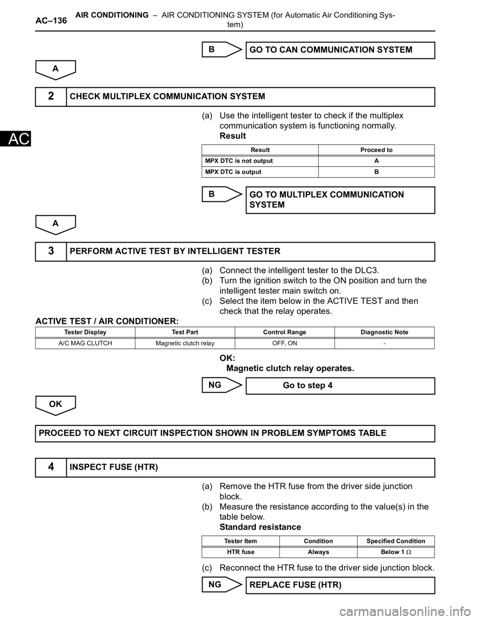
(a) Remove the MG CLT relay from the No. 3 relay block.
(b) Measure the resistance according to the value(s) in the
table below.
Standard resistance
(c) Install the MG CLT relay to the No. 3 relay block.
NG
OK
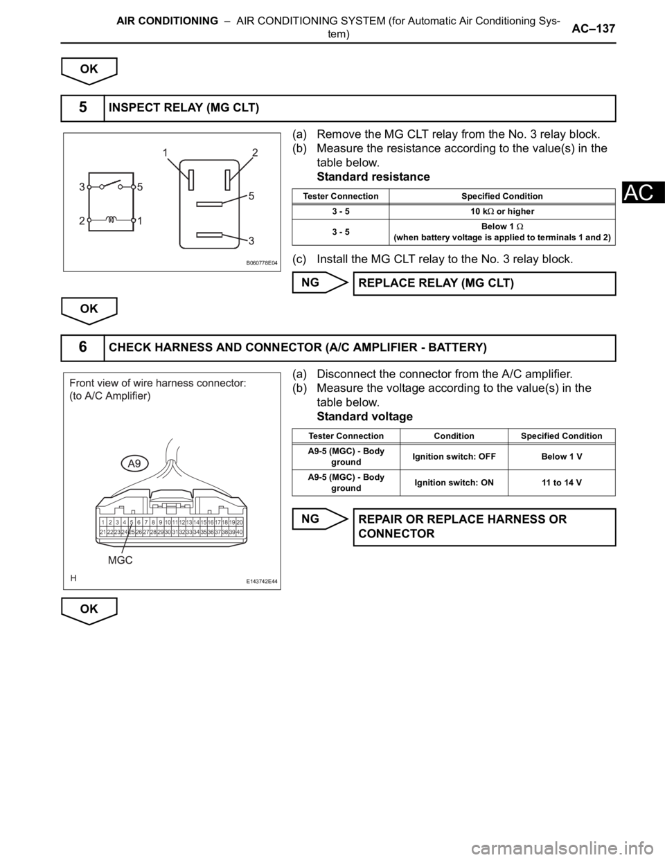
(a) Disconnect the connector from the A/C amplifier.
(b) Measure the voltage according to the value(s) in the
table below.
Standard voltage
NG
OK
5INSPECT RELAY (MG CLT)
B060778E04
Tester Connection Specified Condition
3 - 5 10 k
or higher
3 - 5Below 1
(when battery voltage is applied to terminals 1 and 2)
REPLACE RELAY (MG CLT)
6CHECK HARNESS AND CONNECTOR (A/C AMPLIFIER - BATTERY)
E143742E44
Tester Connection Condition Specified Condition
A9-5 (MGC) - Body
groundIgnition switch: OFF Below 1 V
A9-5 (MGC) - Body
groundIgnition switch: ON 11 to 14 V
REPAIR OR REPLACE HARNESS OR
CONNECTOR
Page 2882 of 3000

AIR CONDITIONING – AIR CONDITIONING SYSTEM (for Automatic Air Conditioning Sys-
tem)AC–139
AC
OK
(a) Measure the resistance according to the value(s) in the
table below.
Standard resistance
(b) When connector terminal A1 is connected to the positive
(+) battery terminal, check that the following occurs: 1)
the magnetic clutch's operating sound can be heard, and
2) the magnetic clutch's hub and rotor lock.
NG
OK
(a) Remove the MG CLT relay from the No. 3 relay block.
(b) Turn the ignition switch to the ON position.
(c) Measure the voltage according to the value(s) in the
table below.
Standard voltage
NG
OK
9INSPECT MAGNETIC CLUTCH
E147609E01
Tester Connection Condition Specified Condition
A-1 - Body ground Always 3.4 to 3.8
REPLACE MAGNETIC CLUTCH
10CHECK HARNESS AND CONNECTOR (NO. 3 RELAY BLOCK - BATTERY)
E147378E01
Tester Connection Specified Condition
Relay block MG CLT relay terminal 5 - Body ground 11 to 14 V
Relay block MG CLT relay terminal 1 - Body ground 11 to 14 V
REPAIR OR REPLACE HARNESS OR
CONNECTOR (NO. 3 RELAY BLOCK -
COMPRESSOR AND MAGNETIC CLUTCH)
REPAIR OR REPLACE HARNESS OR CONNECTOR