Page 2752 of 3000

POWER STEERING – RACK AND PINION POWER STEERING GEARPS–41
PS
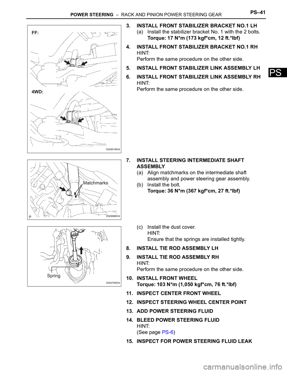
3. INSTALL FRONT STABILIZER BRACKET NO.1 LH
(a) Install the stabilizer bracket No. 1 with the 2 bolts.
Torque: 17 N*m (173 kgf*cm, 12 ft.*lbf)
4. INSTALL FRONT STABILIZER BRACKET NO.1 RH
HINT:
Perform the same procedure on the other side.
5. INSTALL FRONT STABILIZER LINK ASSEMBLY LH
6. INSTALL FRONT STABILIZER LINK ASSEMBLY RH
HINT:
Perform the same procedure on the other side.
7. INSTALL STEERING INTERMEDIATE SHAFT
ASSEMBLY
(a) Align matchmarks on the intermediate shaft
assembly and power steering gear assembly.
(b) Install the bolt.
Torque: 36 N*m (367 kgf*cm, 27 ft.*lbf)
(c) Install the dust cover.
HINT:
Ensure that the springs are installed tightly.
8. INSTALL TIE ROD ASSEMBLY LH
9. INSTALL TIE ROD ASSEMBLY RH
HINT:
Perform the same procedure on the other side.
10. INSTALL FRONT WHEEL
Torque: 103 N*m (1,050 kgf*cm, 76 ft.*lbf)
11. INSPECT CENTER FRONT WHEEL
12. INSPECT STEERING WHEEL CENTER POINT
13. ADD POWER STEERING FLUID
14. BLEED POWER STEERING FLUID
HINT:
(See page PS-6)
15. INSPECT FOR POWER STEERING FLUID LEAK
D030615E04
D029986E04
D030704E04
Page 2959 of 3000
AIR CONDITIONING – COMPRESSOR AND MAGNETIC CLUTCHAC–233
AC
(d) Install the suction hose sub-assembly onto the
compressor and magnetic clutch with the bolt.
Torque: 5.4 N*m (55 kgf*cm, 48 in.*lbf)
3. INSTALL DISCHARGE HOSE SUB-ASSEMBLY
(a) Remove the attached vinyl tape from the hose.
(b) Apply sufficient compressor oil to a new O-ring and
the fitting surface of the compressor and magnetic
clutch.
Compressor oil:
ND-OIL 8 or equivalent
(c) Install the O-ring onto the discharge hose sub-
assembly.
(d) Install the discharge hose sub-assembly onto the
compressor and magnetic clutch with the bolt.
Torque: 5.4 N*m (55 kgf*cm, 48 in.*lbf)
4. INSTALL RADIATOR AND FAN ASSEMBLY
(See page CO-39)
5. INSTALL V-RIBBED BELT (See page EM-7)
6. INSTALL FRONT FENDER APRON SEAL RH (See
page EM-62)
7. INSTALL FRONT WHEEL RH
8. CHARGE WITH REFRIGERANT (See page AC-173)
9. WARM UP ENGINE
10. INSPECT FOR REFRIGERANT LEAK (See page AC-
173)
E145265
E145264
Page 2973 of 3000
AIR CONDITIONING – COMPRESSOR AND MAGNETIC CLUTCHAC–233
AC
(d) Install the suction hose sub-assembly onto the
compressor and magnetic clutch with the bolt.
Torque: 5.4 N*m (55 kgf*cm, 48 in.*lbf)
3. INSTALL DISCHARGE HOSE SUB-ASSEMBLY
(a) Remove the attached vinyl tape from the hose.
(b) Apply sufficient compressor oil to a new O-ring and
the fitting surface of the compressor and magnetic
clutch.
Compressor oil:
ND-OIL 8 or equivalent
(c) Install the O-ring onto the discharge hose sub-
assembly.
(d) Install the discharge hose sub-assembly onto the
compressor and magnetic clutch with the bolt.
Torque: 5.4 N*m (55 kgf*cm, 48 in.*lbf)
4. INSTALL RADIATOR AND FAN ASSEMBLY
(See page CO-39)
5. INSTALL V-RIBBED BELT (See page EM-7)
6. INSTALL FRONT FENDER APRON SEAL RH (See
page EM-62)
7. INSTALL FRONT WHEEL RH
8. CHARGE WITH REFRIGERANT (See page AC-173)
9. WARM UP ENGINE
10. INSPECT FOR REFRIGERANT LEAK (See page AC-
173)
E145265
E145264