Page 2460 of 3000

BC–98BRAKE CONTROL – VEHICLE STABILITY CONTROL SYSTEM
BC
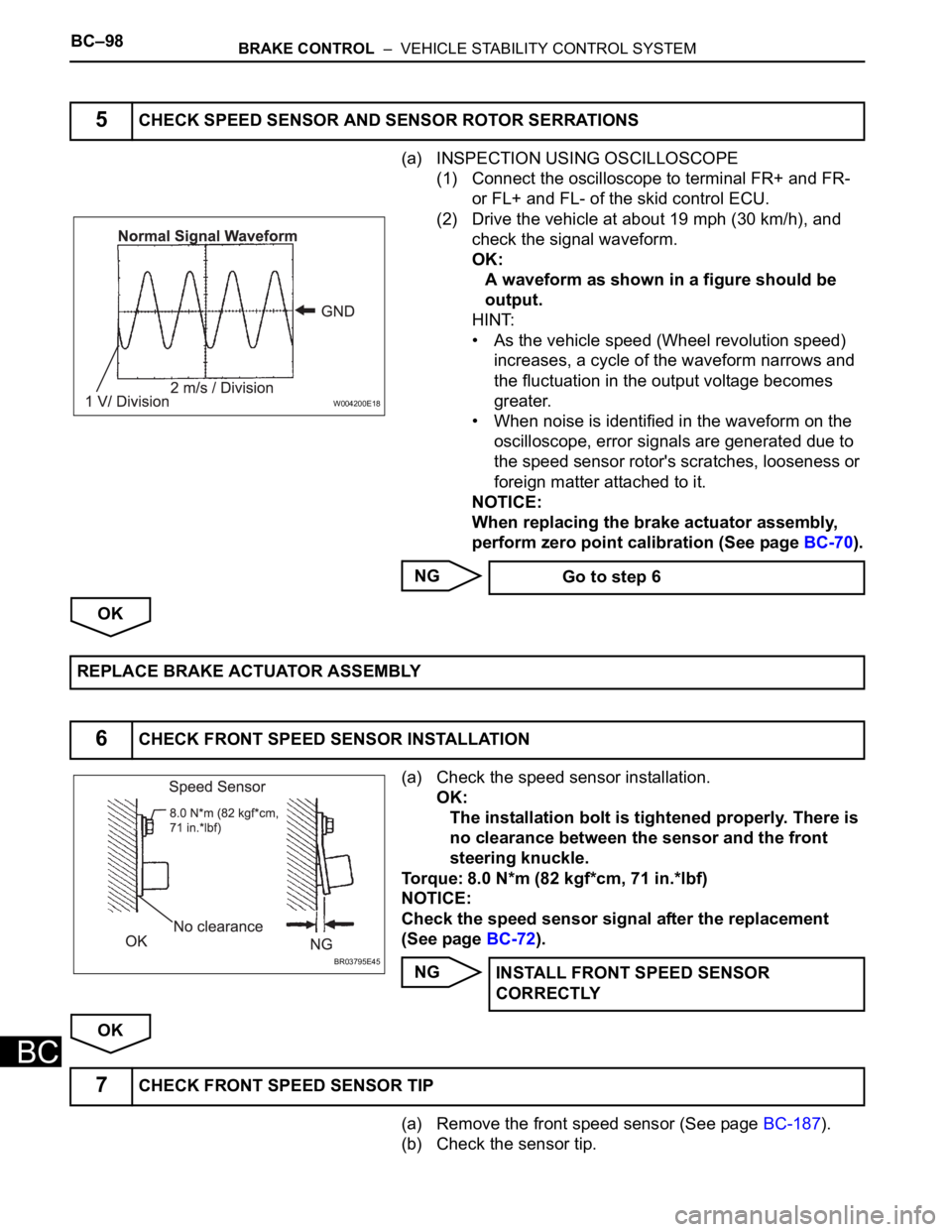
(a) INSPECTION USING OSCILLOSCOPE
(1) Connect the oscilloscope to terminal FR+ and FR-
or FL+ and FL- of the skid control ECU.
(2) Drive the vehicle at about 19 mph (30 km/h), and
check the signal waveform.
OK:
A waveform as shown in a figure should be
output.
HINT:
• As the vehicle speed (Wheel revolution speed)
increases, a cycle of the waveform narrows and
the fluctuation in the output voltage becomes
greater.
• When noise is identified in the waveform on the
oscilloscope, error signals are generated due to
the speed sensor rotor's scratches, looseness or
foreign matter attached to it.
NOTICE:
When replacing the brake actuator assembly,
perform zero point calibration (See page BC-70).
NG
OK
(a) Check the speed sensor installation.
OK:
The installation bolt is tightened properly. There is
no clearance between the sensor and the front
steering knuckle.
Torque: 8.0 N*m (82 kgf*cm, 71 in.*lbf)
NOTICE:
Check the speed sensor signal after the replacement
(See page BC-72).
NG
OK
(a) Remove the front speed sensor (See page BC-187).
(b) Check the sensor tip.
5CHECK SPEED SENSOR AND SENSOR ROTOR SERRATIONS
W004200E18
Go to step 6
REPLACE BRAKE ACTUATOR ASSEMBLY
6CHECK FRONT SPEED SENSOR INSTALLATION
BR03795E45INSTALL FRONT SPEED SENSOR
CORRECTLY
7CHECK FRONT SPEED SENSOR TIP
Page 2595 of 3000

BRAKE – BRAKE FLUIDBR–3
BR
BRAKE FLUID
BLEEDING
HINT:
If any work is performed on the brake system or if air in the
brake lines is suspected, bleed the air out of the brake
system.
NOTICE:
Wash the brake fluid off immediately if it adheres to any
painted surfaces.
1. REMOVE COWL TOP PANEL SUB-ASSEMBLY
OUTER FRONT (See page SP-13)
2. FILL RESERVOIR WITH BRAKE FLUID
Fluid:
SAE J1703 or FMVSS No. 116 DOT3
NOTICE:
Perform the procedure after confirming the sub-tank
at the upper of the master cylinder assembly is filled
enough.
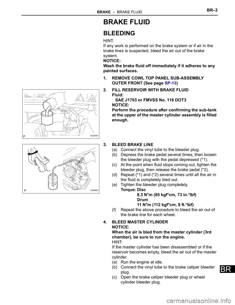
3. BLEED BRAKE LINE
(a) Connect the vinyl tube to the bleeder plug.
(b) Depress the brake pedal several times, then loosen
the bleeder plug with the pedal depressed (*1).
(c) At the point when fluid stops coming out, tighten the
bleeder plug, then release the brake pedal (*2).
(d) Repeat (*1) and (*2) several times until all the air in
the fluid is completely bled out.
(e) Tighten the bleeder plug completely.
Torque: Disc
8.3 N*m (85 kgf*cm, 73 in.*lbf)
Drum
11 N*m (112 kgf*cm, 8 ft.*lbf)
(f) Repeat the above procedure to bleed the air out of
the brake line for each wheel.
4. BLEED MASTER CYLINDER
NOTICE:
When the air is bled from the master cylinder (3rd
chamber), be sure to run the engine.
HINT:
If the master cylinder has been disassembled or if the
reservoir becomes empty, bleed the air out of the master
cylinder.
(a) Run the engine at idle.
(b) Connect the vinyl tube to the brake caliper bleeder
plug.
(c) Open the brake caliper bleeder plug or wheel
cylinder bleeder plug.
G024304
C080826
Page 2596 of 3000

BR–4BRAKE – BRAKE FLUID
BR
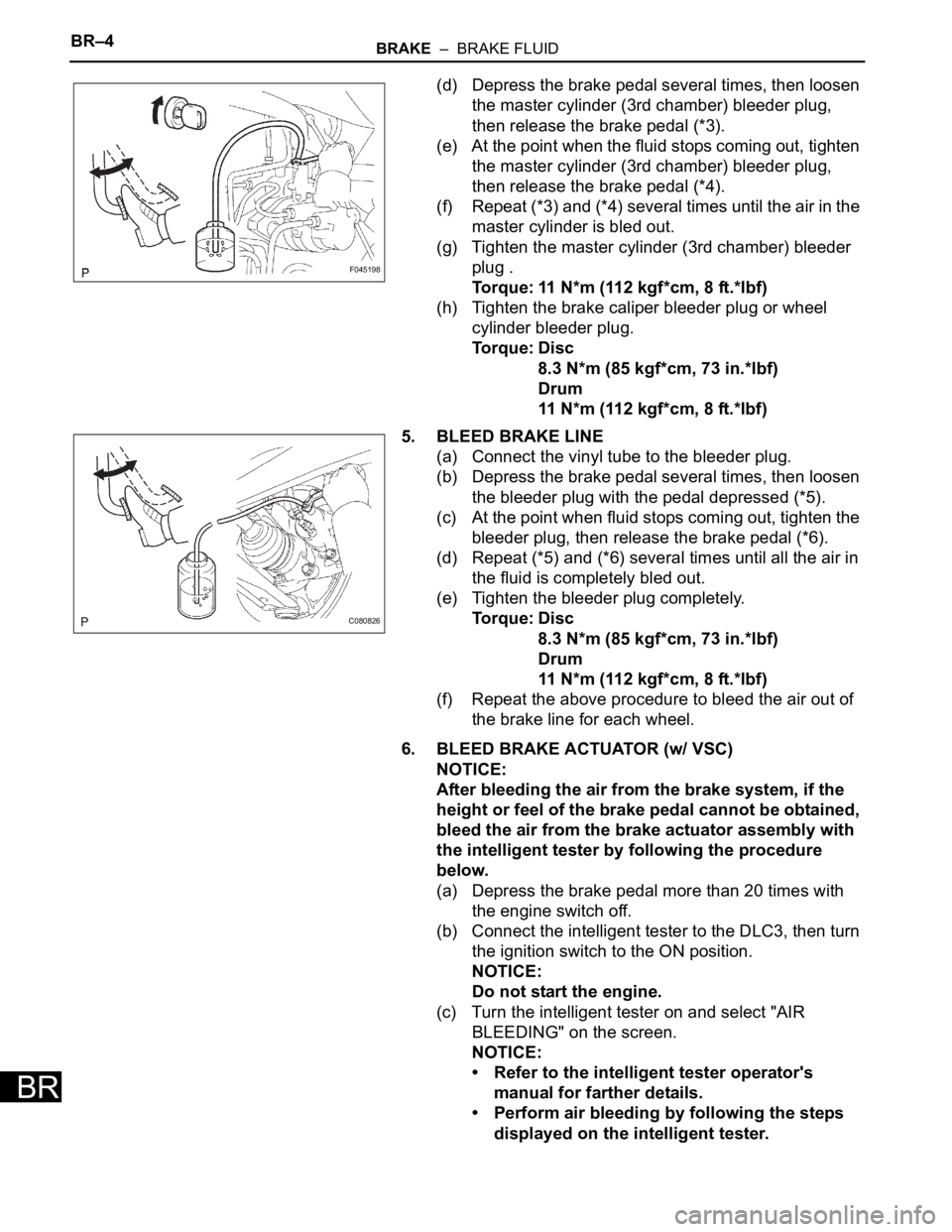
(d) Depress the brake pedal several times, then loosen
the master cylinder (3rd chamber) bleeder plug,
then release the brake pedal (*3).
(e) At the point when the fluid stops coming out, tighten
the master cylinder (3rd chamber) bleeder plug,
then release the brake pedal (*4).
(f) Repeat (*3) and (*4) several times until the air in the
master cylinder is bled out.
(g) Tighten the master cylinder (3rd chamber) bleeder
plug .
Torque: 11 N*m (112 kgf*cm, 8 ft.*lbf)
(h) Tighten the brake caliper bleeder plug or wheel
cylinder bleeder plug.
Torque: Disc
8.3 N*m (85 kgf*cm, 73 in.*lbf)
Drum
11 N*m (112 kgf*cm, 8 ft.*lbf)
5. BLEED BRAKE LINE
(a) Connect the vinyl tube to the bleeder plug.
(b) Depress the brake pedal several times, then loosen
the bleeder plug with the pedal depressed (*5).
(c) At the point when fluid stops coming out, tighten the
bleeder plug, then release the brake pedal (*6).
(d) Repeat (*5) and (*6) several times until all the air in
the fluid is completely bled out.
(e) Tighten the bleeder plug completely.
Torque: Disc
8.3 N*m (85 kgf*cm, 73 in.*lbf)
Drum
11 N*m (112 kgf*cm, 8 ft.*lbf)
(f) Repeat the above procedure to bleed the air out of
the brake line for each wheel.
6. BLEED BRAKE ACTUATOR (w/ VSC)
NOTICE:
After bleeding the air from the brake system, if the
height or feel of the brake pedal cannot be obtained,
bleed the air from the brake actuator assembly with
the intelligent tester by following the procedure
below.
(a) Depress the brake pedal more than 20 times with
the engine switch off.
(b) Connect the intelligent tester to the DLC3, then turn
the ignition switch to the ON position.
NOTICE:
Do not start the engine.
(c) Turn the intelligent tester on and select "AIR
BLEEDING" on the screen.
NOTICE:
• Refer to the intelligent tester operator's
manual for farther details.
• Perform air bleeding by following the steps
displayed on the intelligent tester.
F045198
C080826
Page 2602 of 3000
BR–24BRAKE – BRAKE BOOSTER
BR
15. INSTALL INSTRUMENT PANEL SAFETY PAD INSERT
SUB-ASSEMBLY NO. 1
(a) Install the instrument panel safety pad insert sub-
assembly No. 1 with the 4 bolts.
16. INSTALL INSTRUMENT PANEL FINISH PANEL SUB-
ASSEMBLY LOWER LH
(a) Install the instrument panel finish panel sub-
assembly lower LH with the 2 bolts.
17. INSTALL COWL SIDE TRIM BOARD LH
(a) Install the cowl trim board plate LH with the nut.
18. INSTALL FRONT DOOR SCUFF PLATE LH
19. INSTALL COWL TOP PANEL SUB-ASSEMBLY
OUTER FRONT
20. INSTALL FRONT WHEEL
Torque: 103 N*m (1,050 kgf*cm, 76 ft.*lbf)
21. INSPECT BRAKE PEDAL HEIGHT (See page BR-9)
22. CHECK BRAKE ACTUATOR WITH INTELLIGENT
TESTER
Type of Brake Actuator See Procedure
With VSCBC-178
Without VSCBC-183
Page 2617 of 3000
BRAKE – FRONT BRAKEBR–31
BR
7. REMOVE FRONT DISC BRAKE CYLINDER
ASSEMBLY LH
(a) Install the front disc brake cylinder sub-assembly
with the 2 bolts.
Torque: 34 N*m (350 kgf*cm, 25 ft.*lbf)
(b) Install a 2 new gaskets and flexible hose with the
union bolt.
Torque: 29 N*m (296 kgf*cm, 21 ft.*lbf)
HINT:
Install the flexible hose lock securely in the lock hole
in the disc brake cylinder.
8. FILL RESERVOIR WITH BRAKE FLUID (See page BR-
3)
9. BLEED BRAKE MASTER CYLINDER (See page BR-3)
10. BLEED BRAKE LINE (See page BR-4)
11. BLEED BRAKE ACTUATOR (w/ VSC) (See page BR-
4)
12. CHECK FLUID LEVEL IN RESERVOIR (See page BR-
7)
13. CHECK BRAKE FLUID LEAKAGE
14. INSTALL FRONT WHEEL
Torque: 103 N*m (1,050 kgf*cm, 76 ft.*lbf)
C097868
Page 2633 of 3000
BR–36BRAKE – REAR DISC BRAKE
BR
(b) Using SST and a spanner, connect the rear brake
tube No. 4.
SST 09023-00101
Torque: 15 N*m (155 kgf*cm, 11 ft.*lbf)
8. FILL RESERVOIR WITH BRAKE FLUID (See page BR-
3)
9. BLEED BRAKE MASTER CYLINDER (See page BR-3)
10. BLEED BRAKE LINE (See page BR-4)
11. BLEED BRAKE ACTUATOR (w/ VSC) (See page BR-
4)
12. CHECK FLUID LEVEL IN RESERVOIR (See page BR-
7)
13. CHECK BRAKE FLUID LEAKAGE
14. INSTALL REAR WHEEL
Torque: 103 N*m (1,050 kgf*cm, 76 ft.*lbf)
C065884
Page 2635 of 3000
BR–36BRAKE – REAR DISC BRAKE
BR
(b) Using SST and a spanner, connect the rear brake
tube No. 4.
SST 09023-00101
Torque: 15 N*m (155 kgf*cm, 11 ft.*lbf)
8. FILL RESERVOIR WITH BRAKE FLUID (See page BR-
3)
9. BLEED BRAKE MASTER CYLINDER (See page BR-3)
10. BLEED BRAKE LINE (See page BR-4)
11. BLEED BRAKE ACTUATOR (w/ VSC) (See page BR-
4)
12. CHECK FLUID LEVEL IN RESERVOIR (See page BR-
7)
13. CHECK BRAKE FLUID LEAKAGE
14. INSTALL REAR WHEEL
Torque: 103 N*m (1,050 kgf*cm, 76 ft.*lbf)
C065884
Page 2640 of 3000

BR–40BRAKE – REAR DRUM BRAKE
BR
REASSEMBLY
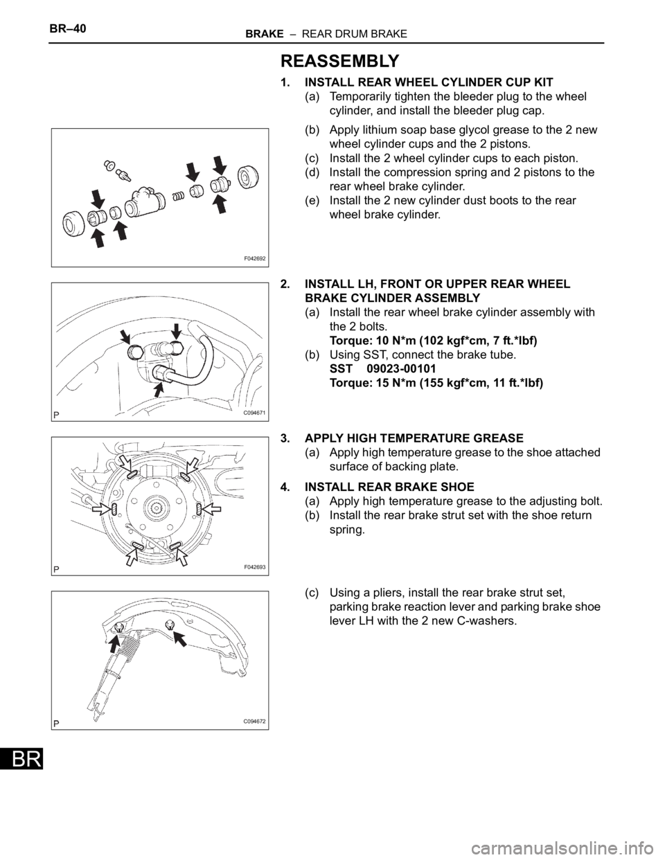
1. INSTALL REAR WHEEL CYLINDER CUP KIT
(a) Temporarily tighten the bleeder plug to the wheel
cylinder, and install the bleeder plug cap.
(b) Apply lithium soap base glycol grease to the 2 new
wheel cylinder cups and the 2 pistons.
(c) Install the 2 wheel cylinder cups to each piston.
(d) Install the compression spring and 2 pistons to the
rear wheel brake cylinder.
(e) Install the 2 new cylinder dust boots to the rear
wheel brake cylinder.
2. INSTALL LH, FRONT OR UPPER REAR WHEEL
BRAKE CYLINDER ASSEMBLY
(a) Install the rear wheel brake cylinder assembly with
the 2 bolts.
Torque: 10 N*m (102 kgf*cm, 7 ft.*lbf)
(b) Using SST, connect the brake tube.
SST 09023-00101
Torque: 15 N*m (155 kgf*cm, 11 ft.*lbf)
3. APPLY HIGH TEMPERATURE GREASE
(a) Apply high temperature grease to the shoe attached
surface of backing plate.
4. INSTALL REAR BRAKE SHOE
(a) Apply high temperature grease to the adjusting bolt.
(b) Install the rear brake strut set with the shoe return
spring.
(c) Using a pliers, install the rear brake strut set,
parking brake reaction lever and parking brake shoe
lever LH with the 2 new C-washers.
F042692
C094671
F042693
C094672