Page 2184 of 3000
SUSPENSION – FRONT SHOCK ABSORBER WITH COIL SPRINGSP–19
SP
2. INSTALL FRONT STABILIZER LINK ASSEMBLY LH
(a) Install the front stabilizer link assembly LH with the
nut.
Torque: 74 N*m (755 kgf*cm, 55 ft.*lbf)
HINT:
If the ball joint turns together with the nut, use a
hexagon (6 mm) wrench to hold the stud.
3. INSTALL COWL TOP PANEL SUB-ASSEMBLY
OUTER FRONT
(a) Install the cowl top brace and cowl top panel sub-
assembly outer front with the 9 bolts.
Torque: 7.5 N*m (76 kgf*cm, 66 in.*lbf)
(b) Connect the wire harness to the cowl top panel sub-
assembly outer front.
4. INSTALL WINDSHIELD WIPER MOTOR & LINK
ASSEMBLY
HINT:
(See page WW-3)
5. INSTALL FR WIPER ARM LH
HINT:
(See page WW-3)
6. INSTALL FR WIPER ARM RH
HINT:
(See page WW-3)
7. INSTALL FRONT WHEEL
Torque: 103 N*m (1,050 kgf*cm, 76 ft.*lbf)
8. INSPECT AND ADJUST FRONT WHEEL ALIGNMENT
HINT:
(See page SP-4)
F045196
F049306E01
Page 2187 of 3000

SUSPENSION – FRONT WHEEL ALIGNMENTSP–5
SP
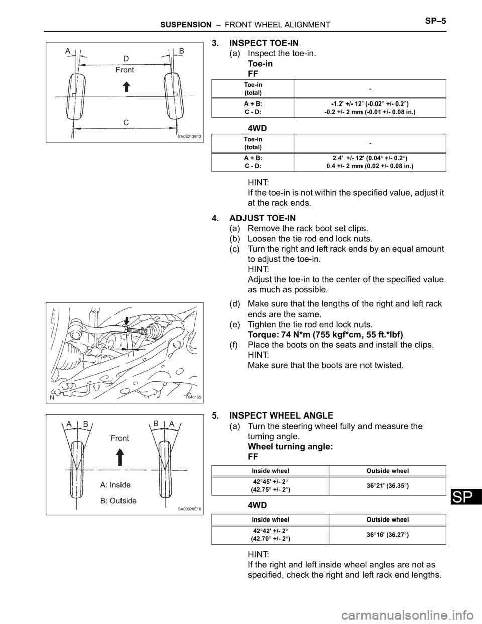
3. INSPECT TOE-IN
(a) Inspect the toe-in.
To e - i n
FF
4WD
HINT:
If the toe-in is not within the specified value, adjust it
at the rack ends.
4. ADJUST TOE-IN
(a) Remove the rack boot set clips.
(b) Loosen the tie rod end lock nuts.
(c) Turn the right and left rack ends by an equal amount
to adjust the toe-in.
HINT:
Adjust the toe-in to the center of the specified value
as much as possible.
(d) Make sure that the lengths of the right and left rack
ends are the same.
(e) Tighten the tie rod end lock nuts.
Torque: 74 N*m (755 kgf*cm, 55 ft.*lbf)
(f) Place the boots on the seats and install the clips.
HINT:
Make sure that the boots are not twisted.
5. INSPECT WHEEL ANGLE
(a) Turn the steering wheel fully and measure the
turning angle.
Wheel turning angle:
FF
4WD
HINT:
If the right and left inside wheel angles are not as
specified, check the right and left rack end lengths.
SA03213E12
To e - i n
(total)-
A + B:
C - D:-1.2' +/- 12' (-0.02
+/- 0.2)
-0.2 +/- 2 mm (-0.01 +/- 0.08 in.)
To e - i n
(total)-
A + B:
C - D:2.4' +/- 12' (0.04
+/- 0.2)
0.4 +/- 2 mm (0.02 +/- 0.08 in.)
F040165
SA00028E10
Inside wheel Outside wheel
42
45' +/- 2(42.75 +/- 2)3621' (36.35)
Inside wheel Outside wheel
42
42' +/- 2
(42.70 +/- 2)3616' (36.27)
Page 2189 of 3000
SUSPENSION – FRONT WHEEL ALIGNMENTSP–7
SP
(e) Adjust the camber by pushing or pulling the lower
side of the shock absorber in the direction in which
the camber adjustment is required.
(f) Tighten the nuts.
Torque: 210 N*m (2140 kgf*cm, 155 ft.*lbf)
NOTICE:
When installing the nut, stop the bolt from
rotating and tighten the nut.
(g) Install the front wheel.
Torque: 103 N*m (1050 kgf*cm, 76 ft.*lbf)
(h) Check the camber.
C093869E02
C128571E01
Page 2194 of 3000

SP–24SUSPENSION – FRONT LOWER BALL JOINT
SP
REMOVAL
1. REMOVE FRONT WHEEL
2. REMOVE FRONT AXLE HUB LH NUT
HINT:
(See page AH-4)
SST 09930-00010
3. SEPARATE SPEED SENSOR FRONT LH
HINT:
(See page AH-4)
4. SEPARATE FRONT DISC BRAKE CALIPER
ASSEMBLY LH
HINT:
(See page AH-4)
5. REMOVE FRONT DISC
6. SEPARATE TIE ROD ASSEMBLY LH
HINT:
(See page AH-4)
SST 09628-62011
7. SEPARATE FRONT SUSPENSION ARM SUB-
ASSEMBLY LOWER NO.1 LH
HINT:
(See page AH-4)
8. REMOVE FRONT AXLE ASSEMBLY LH
HINT:
(See page AH-4)
9. REMOVE LOWER BALL JOINT ASSEMBLY FRONT
LH
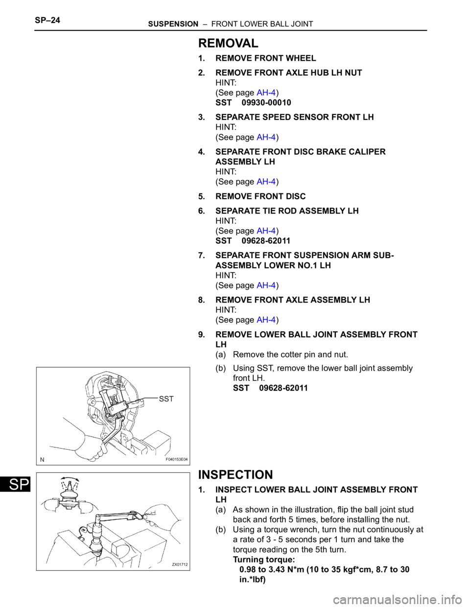
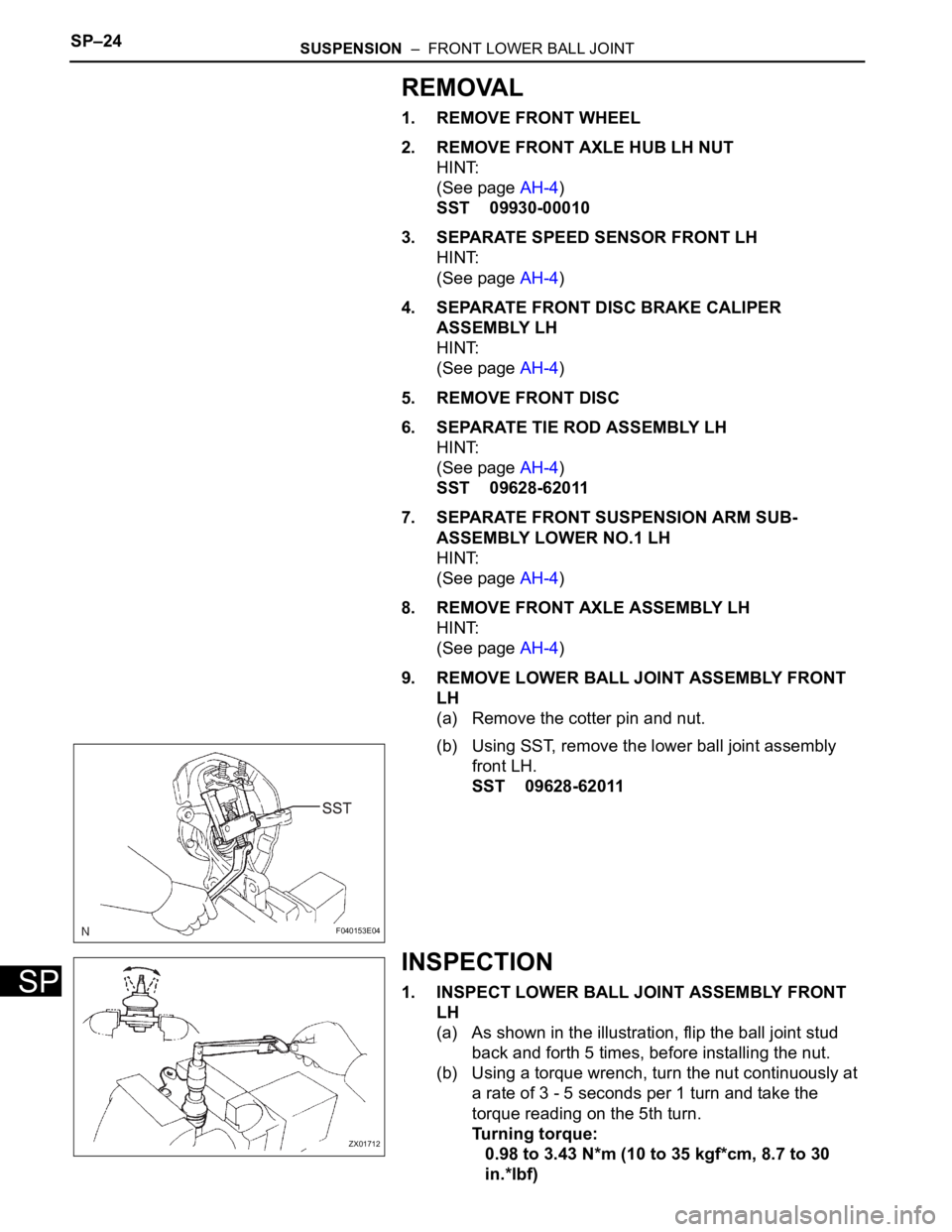
(a) Remove the cotter pin and nut.
(b) Using SST, remove the lower ball joint assembly
front LH.
SST 09628-62011
INSPECTION
1. INSPECT LOWER BALL JOINT ASSEMBLY FRONT
LH
(a) As shown in the illustration, flip the ball joint stud
back and forth 5 times, before installing the nut.
(b) Using a torque wrench, turn the nut continuously at
a rate of 3 - 5 seconds per 1 turn and take the
torque reading on the 5th turn.
Turning torque:
0.98 to 3.43 N*m (10 to 35 kgf*cm, 8.7 to 30
in.*lbf)
F040153E04
ZX01712
Page 2195 of 3000
SUSPENSION – FRONT LOWER BALL JOINTSP–25
SP
INSTALLATION
1. INSTALL LOWER BALL JOINT ASSEMBLY FRONT
LH
(a) Install the lower ball joint assembly front LH and
tighten the nut.
Torque: 123 N*m (1,250 kgf*cm, 91 ft.*lbf)
(b) Install a new cotter pin.
NOTICE:
If the holes for the cotter pin are not aligned,
tighten the nut further up to 60
.
2. INSTALL FRONT AXLE ASSEMBLY LH
HINT:
(See page AH-4)
3. INSTALL FRONT SUSPENSION ARM SUB-
ASSEMBLY LOWER NO.1 LH
HINT:
(See page AH-4)
4. INSTALL TIE ROD ASSEMBLY LH
HINT:
(See page AH-4)
5. INSTALL FRONT DISC
6. INSTALL FRONT DISC BRAKE CALIPER ASSEMBLY
LH
HINT:
(See page AH-4)
7. INSTALL SPEED SENSOR FRONT LH
HINT:
(See page AH-4)
8. INSTALL FRONT AXLE HUB LH NUT
HINT:
(See page AH-4)
9. INSTALL FRONT WHEEL
Torque: 103 N*m (1,050 kgf*cm, 76 ft.*lbf)
10. INSPECT AND ADJUST FRONT WHEEL ALIGNMENT
HINT:
(See page SP-4)
11. CHECK ABS SPEED SENSOR SIGNAL
w/o VSC: (See page BC-2).
w/ VSC: (See page BC-68).
Page 2202 of 3000
SUSPENSION – FRONT SHOCK ABSORBER WITH COIL SPRINGSP–19
SP
2. INSTALL FRONT STABILIZER LINK ASSEMBLY LH
(a) Install the front stabilizer link assembly LH with the
nut.
Torque: 74 N*m (755 kgf*cm, 55 ft.*lbf)
HINT:
If the ball joint turns together with the nut, use a
hexagon (6 mm) wrench to hold the stud.
3. INSTALL COWL TOP PANEL SUB-ASSEMBLY
OUTER FRONT
(a) Install the cowl top brace and cowl top panel sub-
assembly outer front with the 9 bolts.
Torque: 7.5 N*m (76 kgf*cm, 66 in.*lbf)
(b) Connect the wire harness to the cowl top panel sub-
assembly outer front.
4. INSTALL WINDSHIELD WIPER MOTOR & LINK
ASSEMBLY
HINT:
(See page WW-3)
5. INSTALL FR WIPER ARM LH
HINT:
(See page WW-3)
6. INSTALL FR WIPER ARM RH
HINT:
(See page WW-3)
7. INSTALL FRONT WHEEL
Torque: 103 N*m (1,050 kgf*cm, 76 ft.*lbf)
8. INSPECT AND ADJUST FRONT WHEEL ALIGNMENT
HINT:
(See page SP-4)
F045196
F049306E01
Page 2208 of 3000

SP–30SUSPENSION – FRONT STABILIZER BAR (for 2WD)
SP
INSTALLATION
1. INSTALL STABILIZER BAR FRONT
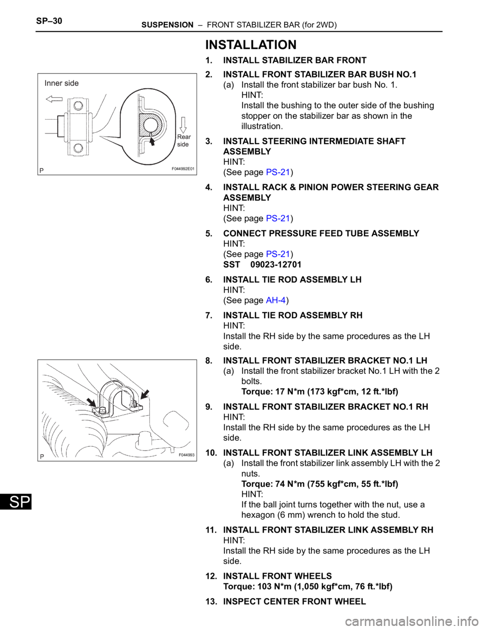
2. INSTALL FRONT STABILIZER BAR BUSH NO.1
(a) Install the front stabilizer bar bush No. 1.
HINT:
Install the bushing to the outer side of the bushing
stopper on the stabilizer bar as shown in the
illustration.
3. INSTALL STEERING INTERMEDIATE SHAFT
ASSEMBLY
HINT:
(See page PS-21)
4. INSTALL RACK & PINION POWER STEERING GEAR
ASSEMBLY
HINT:
(See page PS-21)
5. CONNECT PRESSURE FEED TUBE ASSEMBLY
HINT:
(See page PS-21)
SST 09023-12701
6. INSTALL TIE ROD ASSEMBLY LH
HINT:
(See page AH-4)
7. INSTALL TIE ROD ASSEMBLY RH
HINT:
Install the RH side by the same procedures as the LH
side.
8. INSTALL FRONT STABILIZER BRACKET NO.1 LH
(a) Install the front stabilizer bracket No.1 LH with the 2
bolts.
Torque: 17 N*m (173 kgf*cm, 12 ft.*lbf)
9. INSTALL FRONT STABILIZER BRACKET NO.1 RH
HINT:
Install the RH side by the same procedures as the LH
side.
10. INSTALL FRONT STABILIZER LINK ASSEMBLY LH
(a) Install the front stabilizer link assembly LH with the 2
nuts.
Torque: 74 N*m (755 kgf*cm, 55 ft.*lbf)
HINT:
If the ball joint turns together with the nut, use a
hexagon (6 mm) wrench to hold the stud.
11. INSTALL FRONT STABILIZER LINK ASSEMBLY RH
HINT:
Install the RH side by the same procedures as the LH
side.
12. INSTALL FRONT WHEELS
Torque: 103 N*m (1,050 kgf*cm, 76 ft.*lbf)
13. INSPECT CENTER FRONT WHEEL
F044992E01
F044993
Page 2210 of 3000

SP–24SUSPENSION – FRONT LOWER BALL JOINT
SP
REMOVAL
1. REMOVE FRONT WHEEL
2. REMOVE FRONT AXLE HUB LH NUT
HINT:
(See page AH-4)
SST 09930-00010
3. SEPARATE SPEED SENSOR FRONT LH
HINT:
(See page AH-4)
4. SEPARATE FRONT DISC BRAKE CALIPER
ASSEMBLY LH
HINT:
(See page AH-4)
5. REMOVE FRONT DISC
6. SEPARATE TIE ROD ASSEMBLY LH
HINT:
(See page AH-4)
SST 09628-62011
7. SEPARATE FRONT SUSPENSION ARM SUB-
ASSEMBLY LOWER NO.1 LH
HINT:
(See page AH-4)
8. REMOVE FRONT AXLE ASSEMBLY LH
HINT:
(See page AH-4)
9. REMOVE LOWER BALL JOINT ASSEMBLY FRONT
LH
(a) Remove the cotter pin and nut.
(b) Using SST, remove the lower ball joint assembly
front LH.
SST 09628-62011
INSPECTION
1. INSPECT LOWER BALL JOINT ASSEMBLY FRONT
LH
(a) As shown in the illustration, flip the ball joint stud
back and forth 5 times, before installing the nut.
(b) Using a torque wrench, turn the nut continuously at
a rate of 3 - 5 seconds per 1 turn and take the
torque reading on the 5th turn.
Turning torque:
0.98 to 3.43 N*m (10 to 35 kgf*cm, 8.7 to 30
in.*lbf)
F040153E04
ZX01712