Page 1021 of 3000

EM–622GR-FE ENGINE MECHANICAL – ENGINE ASSEMBLY
EM
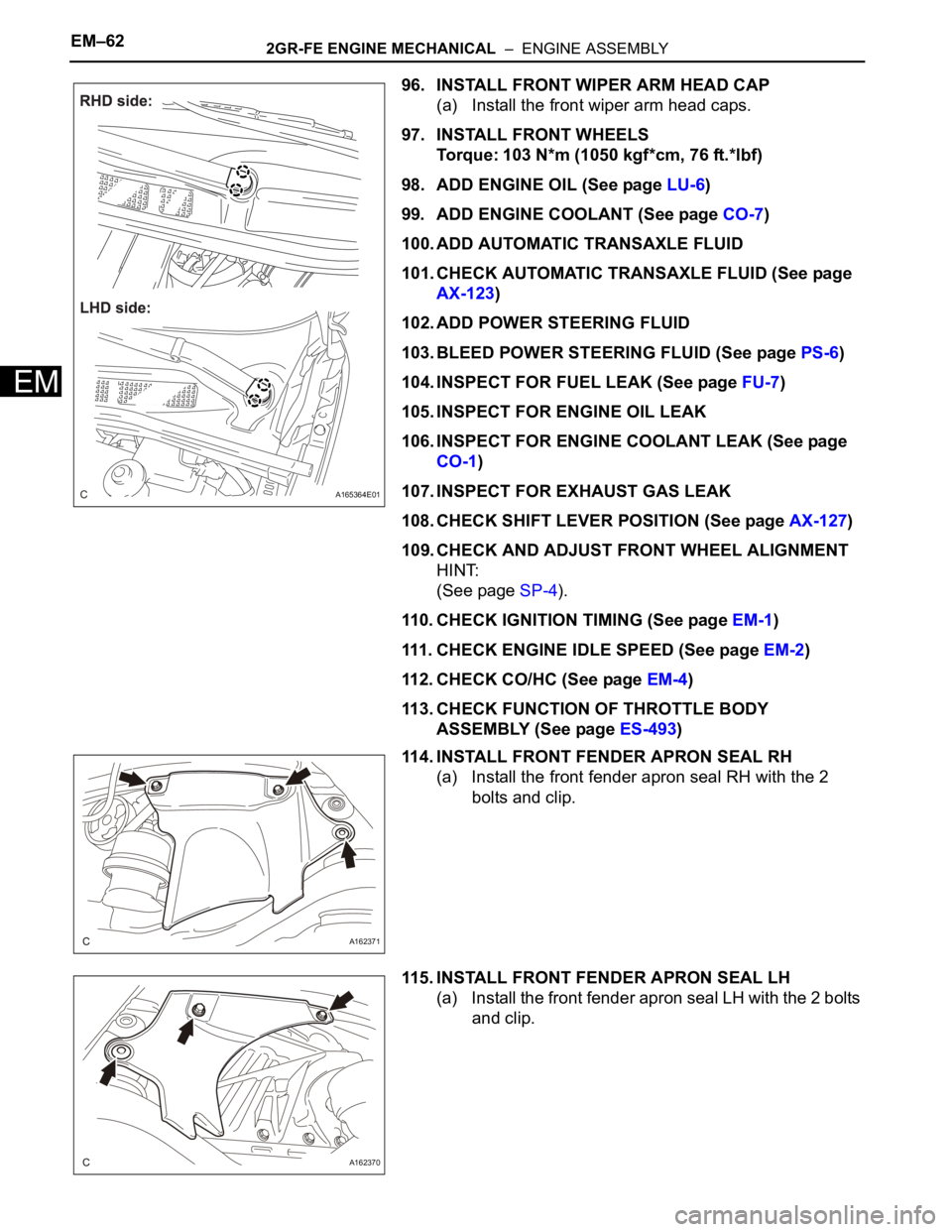
96. INSTALL FRONT WIPER ARM HEAD CAP
(a) Install the front wiper arm head caps.
97. INSTALL FRONT WHEELS
Torque: 103 N*m (1050 kgf*cm, 76 ft.*lbf)
98. ADD ENGINE OIL (See page LU-6)
99. ADD ENGINE COOLANT (See page CO-7)
100. ADD AUTOMATIC TRANSAXLE FLUID
101. CHECK AUTOMATIC TRANSAXLE FLUID (See page
AX-123)
102. ADD POWER STEERING FLUID
103. BLEED POWER STEERING FLUID (See page PS-6)
104. INSPECT FOR FUEL LEAK (See page FU-7)
105. INSPECT FOR ENGINE OIL LEAK
106. INSPECT FOR ENGINE COOLANT LEAK (See page
CO-1)
107. INSPECT FOR EXHAUST GAS LEAK
108. CHECK SHIFT LEVER POSITION (See page AX-127)
109. CHECK AND ADJUST FRONT WHEEL ALIGNMENT
HINT:
(See page SP-4).
110. CHECK IGNITION TIMING (See page EM-1)
111. CHECK ENGINE IDLE SPEED (See page EM-2)
112. CHECK CO/HC (See page EM-4)
113. CHECK FUNCTION OF THROTTLE BODY
ASSEMBLY (See page ES-493)
114. INSTALL FRONT FENDER APRON SEAL RH
(a) Install the front fender apron seal RH with the 2
bolts and clip.
115. INSTALL FRONT FENDER APRON SEAL LH
(a) Install the front fender apron seal LH with the 2 bolts
and clip.
A165364E01
A162371
A162370
Page 1240 of 3000
CO–182GR-FE COOLING – THERMOSTAT
CO
3. INSTALL NO. 2 IDLER PULLEY SUB-ASSEMBLY
(a) Install the idler pulley cover plate and idler pulley
sub-assembly with the bolt.
Torque: 43 N*m (438 kgf*cm, 32 ft.*lbf)
4. CONNECT NO. 2 RADIATOR HOSE
(a) Connect the No. 2 radiator hose to the engine.
5. INSTALL V-RIBBED BELT (See page EM-7)
6. INSTALL FRONT FENDER APRON SEAL RH
7. INSTALL FRONT WHEEL RH
8. ADD ENGINE COOLANT (See page CO-7)
9. INSTALL NO. 1 ENGINE UNDER COVER (See page
EM-63)
10. INSPECT FOR COOLANT LEAK (See page CO-1)
11. INSTALL V-BANK COVER SUB-ASSEMBLY (See
page EM-63)
A162789
A162797
Page 1272 of 3000
CO–182GR-FE COOLING – THERMOSTAT
CO
3. INSTALL NO. 2 IDLER PULLEY SUB-ASSEMBLY
(a) Install the idler pulley cover plate and idler pulley
sub-assembly with the bolt.
Torque: 43 N*m (438 kgf*cm, 32 ft.*lbf)
4. CONNECT NO. 2 RADIATOR HOSE
(a) Connect the No. 2 radiator hose to the engine.
5. INSTALL V-RIBBED BELT (See page EM-7)
6. INSTALL FRONT FENDER APRON SEAL RH
7. INSTALL FRONT WHEEL RH
8. ADD ENGINE COOLANT (See page CO-7)
9. INSTALL NO. 1 ENGINE UNDER COVER (See page
EM-63)
10. INSPECT FOR COOLANT LEAK (See page CO-1)
11. INSTALL V-BANK COVER SUB-ASSEMBLY (See
page EM-63)
A162789
A162797
Page 1369 of 3000

2GR-FE CHARGING – GENERATORCH–29
CH
18. CONNECT RADIATOR RESERVE TANK HOSE OR
PIPE (See page CO-44)
19. INSTALL NO. 1 AIR CLEANER INLET (See page EM-
59)
20. INSTALL FRONT BUMPER ENERGY ABSORBER
21. INSTALL FRONT BUMPER ASSEMBLY (See page ET-
9)
22. INSTALL BATTERY (See page EM-59)
23. INSTALL NO. 2 AIR CLEANER INLET (See page EM-
60)
24. ADD ENGINE COOLANT (See page CO-7)
25. INSPECT FOR COOLANT LEAK (See page CO-1)
26. ADD AUTOMATIC TRANSAXLE FLUID
27. CHECK AUTOMATIC TRANSAXLE FLUID (See page
AX-123)
28. INSTALL FRONT FENDER APRON SEAL RH (See
page EM-62)
29. INSTALL NO. 1 ENGINE UNDER COVER (See page
EM-63)
30. INSTALL FRONT WHEEL RH
Torque: 103 N*m (1050 kgf*cm, 76 ft.*lbf)
31. INSTALL V-BANK COVER SUB-ASSEMBLY (See
page EM-63)
32. VEHICLE PREPARATION FOR HEADLIGHT AIM
ADJUSTMENT (See page LI-71)
33. PREPARATION FOR HEADLIGHT AIMING (Using a
tester) (See page LI-71)
34. PREPARATION FOR HEADLIGHT AIMING (Using a
Screen) (See page LI-72)
35. HEADLIGHT AIMING INSPECTION (See page LI-74)
36. HEADLIGHT AIMING ADJUSTMENT (See page LI-75)
37. VEHICLE PREPARATION FOR FOG LIGHT AIM
ADJUSTMENT (w/ Fog Light) (See page LI-82)
38. PREPARATION FOR FOG LIGHT AIMING (Using a
Screen) (w/ Fog Light) (See page LI-83)
39. FOG LIGHT AIMING INSPECTION (w/ Fog Light) (See
page LI-74)
40. FOG LIGHT AIMING ADJUSTMENT (w/ Fog Light)
(See page LI-85)
Page 1378 of 3000

2GR-FE CHARGING – GENERATORCH–29
CH
18. CONNECT RADIATOR RESERVE TANK HOSE OR
PIPE (See page CO-44)
19. INSTALL NO. 1 AIR CLEANER INLET (See page EM-
59)
20. INSTALL FRONT BUMPER ENERGY ABSORBER
21. INSTALL FRONT BUMPER ASSEMBLY (See page ET-
9)
22. INSTALL BATTERY (See page EM-59)
23. INSTALL NO. 2 AIR CLEANER INLET (See page EM-
60)
24. ADD ENGINE COOLANT (See page CO-7)
25. INSPECT FOR COOLANT LEAK (See page CO-1)
26. ADD AUTOMATIC TRANSAXLE FLUID
27. CHECK AUTOMATIC TRANSAXLE FLUID (See page
AX-123)
28. INSTALL FRONT FENDER APRON SEAL RH (See
page EM-62)
29. INSTALL NO. 1 ENGINE UNDER COVER (See page
EM-63)
30. INSTALL FRONT WHEEL RH
Torque: 103 N*m (1050 kgf*cm, 76 ft.*lbf)
31. INSTALL V-BANK COVER SUB-ASSEMBLY (See
page EM-63)
32. VEHICLE PREPARATION FOR HEADLIGHT AIM
ADJUSTMENT (See page LI-71)
33. PREPARATION FOR HEADLIGHT AIMING (Using a
tester) (See page LI-71)
34. PREPARATION FOR HEADLIGHT AIMING (Using a
Screen) (See page LI-72)
35. HEADLIGHT AIMING INSPECTION (See page LI-74)
36. HEADLIGHT AIMING ADJUSTMENT (See page LI-75)
37. VEHICLE PREPARATION FOR FOG LIGHT AIM
ADJUSTMENT (w/ Fog Light) (See page LI-82)
38. PREPARATION FOR FOG LIGHT AIMING (Using a
Screen) (w/ Fog Light) (See page LI-83)
39. FOG LIGHT AIMING INSPECTION (w/ Fog Light) (See
page LI-74)
40. FOG LIGHT AIMING ADJUSTMENT (w/ Fog Light)
(See page LI-85)
Page 1390 of 3000

U151E AUTOMATIC TRANSAXLE – AUTOMATIC TRANSAXLE SYSTEMAX–13
AX
MECHANICAL SYSTEM TESTS
1. PERFORM MECHANICAL SYSTEM TESTS
(a) Measure the stall speed.
The object of this test is to check the overall
performance of the transaxle and engine by
measuring the stall speeds in the D position.
NOTICE:
• Driving test should be done on a paved road
(a nonskid road).
• Perform the test at the normal operating ATF
(Automatic Transmission Fluid) temperature
50 to 80
C (122 to 176F).
• Do not continuously run this test for longer
than 10 seconds.
• To ensure safety, do this test in a wide, clear
level area which provides good traction.
• The stall test should always be carried out in
pairs. One technician should observe the
conditions of wheels or wheel stoppers
outside the vehicle while the other is doing
the test.
(1) Chock the 4 wheels.
(2) Connect the intelligent tester together with the
CAN VIM (controller area network vehicle
interface module) to the DLC3.
(3) Fully apply the parking brake.
(4) Keep your left foot pressed firmly on the brake
pedal.
(5) Start the engine.
(6) Shift into the D position. Press all the way down
on the accelerator pedal with your right foot.
(7) Quickly read the stall speed at this time.
Stall speed:
2,300 +- 150 rpm
Evaluation:
Problem Possible cause
(a) Stall engine speed is low in D position• Engine power output may be insufficient
• Stator one-way clutch not operating properly
HINT:
If the value is less than the specified value by 600 rpm or more, the
torque converter could be faulty.
(b) Stall engine speed is high in D position• Line pressure is too low
• Forward clutch slipping
• U/D (Underdrive) brake slipping
• U/D (Underdrive) one-way clutch is not operating properly
• No.1 one-way clutch not operating properly
• Improper fluid level
Page 1500 of 3000

U151E AUTOMATIC TRANSAXLE – AUTOMATIC TRANSAXLE SYSTEMAX–13
AX
MECHANICAL SYSTEM TESTS
1. PERFORM MECHANICAL SYSTEM TESTS
(a) Measure the stall speed.
The object of this test is to check the overall
performance of the transaxle and engine by
measuring the stall speeds in the D position.
NOTICE:
• Driving test should be done on a paved road
(a nonskid road).
• Perform the test at the normal operating ATF
(Automatic Transmission Fluid) temperature
50 to 80
C (122 to 176F).
• Do not continuously run this test for longer
than 10 seconds.
• To ensure safety, do this test in a wide, clear
level area which provides good traction.
• The stall test should always be carried out in
pairs. One technician should observe the
conditions of wheels or wheel stoppers
outside the vehicle while the other is doing
the test.
(1) Chock the 4 wheels.
(2) Connect the intelligent tester together with the
CAN VIM (controller area network vehicle
interface module) to the DLC3.
(3) Fully apply the parking brake.
(4) Keep your left foot pressed firmly on the brake
pedal.
(5) Start the engine.
(6) Shift into the D position. Press all the way down
on the accelerator pedal with your right foot.
(7) Quickly read the stall speed at this time.
Stall speed:
2,300 +- 150 rpm
Evaluation:
Problem Possible cause
(a) Stall engine speed is low in D position• Engine power output may be insufficient
• Stator one-way clutch not operating properly
HINT:
If the value is less than the specified value by 600 rpm or more, the
torque converter could be faulty.
(b) Stall engine speed is high in D position• Line pressure is too low
• Forward clutch slipping
• U/D (Underdrive) brake slipping
• U/D (Underdrive) one-way clutch is not operating properly
• No.1 one-way clutch not operating properly
• Improper fluid level
Page 1554 of 3000
U151E AUTOMATIC TRANSAXLE – DIFFERENTIAL OIL SEALAX–159
AX
REMOVAL
1. REMOVE FRONT WHEELS
2. REMOVE ENGINE UNDER COVER NO.1
3. DRAIN AUTOMATIC TRANSAXLE FLUID
(a) Remove the drain plug, gasket and drain ATF.
(b) Install a new gasket and the drain plug.
Torque: 49 N*m (500 kgf*cm, 36 ft.*lbf)
4. REMOVE FRONT DRIVE SHAFT ASSEMBLY LH
HINT:
(See page DS-6)
SST 09520-01010, 09520-24010 (09520-32040)
5. REMOVE FRONT DRIVE SHAFT ASSEMBLY RH (for
2WD)
HINT:
(See page DS-6)
6. REMOVE TRANSAXLE HOUSING OIL SEAL
(a) Using SST, pull out the oil seal.
SST 09308-00010
7. REMOVE DIFFERENTIAL SIDE BEARING RETAINER
OIL SEAL
(a) Using SST, pull out the oil seal.
SST 09308-00010
INSTALLATION
1. INSTALL TRANSAXLE HOUSING OIL SEAL
(a) Using SST and a hammer, install a new oil seal.
SST 09316-60011 (09316-00011)
Oil seal installation depth:
-0.5 to 0.5 mm (-0.020 to 0.020 in.)
(b) Coat the lip of the oil seal with MP grease.
C083057E01
C083058E01
C083054E02