Page 167 of 3000

AH–10AXLE – FRONT AXLE HUB
AH
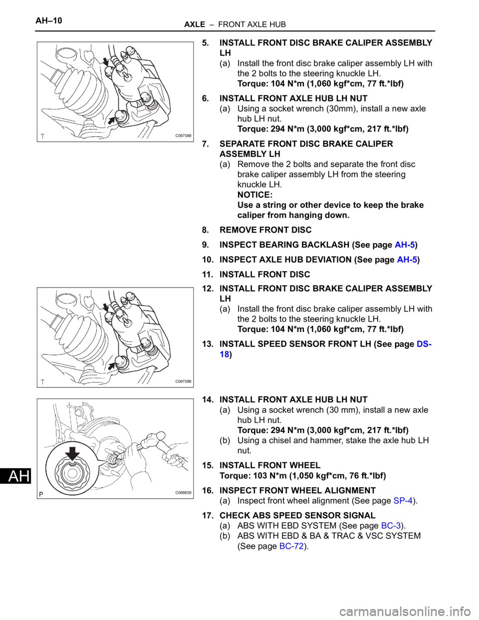
5. INSTALL FRONT DISC BRAKE CALIPER ASSEMBLY
LH
(a) Install the front disc brake caliper assembly LH with
the 2 bolts to the steering knuckle LH.
Torque: 104 N*m (1,060 kgf*cm, 77 ft.*lbf)
6. INSTALL FRONT AXLE HUB LH NUT
(a) Using a socket wrench (30mm), install a new axle
hub LH nut.
Torque: 294 N*m (3,000 kgf*cm, 217 ft.*lbf)
7. SEPARATE FRONT DISC BRAKE CALIPER
ASSEMBLY LH
(a) Remove the 2 bolts and separate the front disc
brake caliper assembly LH from the steering
knuckle LH.
NOTICE:
Use a string or other device to keep the brake
caliper from hanging down.
8. REMOVE FRONT DISC
9. INSPECT BEARING BACKLASH (See page AH-5)
10. INSPECT AXLE HUB DEVIATION (See page AH-5)
11. INSTALL FRONT DISC
12. INSTALL FRONT DISC BRAKE CALIPER ASSEMBLY
LH
(a) Install the front disc brake caliper assembly LH with
the 2 bolts to the steering knuckle LH.
Torque: 104 N*m (1,060 kgf*cm, 77 ft.*lbf)
13. INSTALL SPEED SENSOR FRONT LH (See page DS-
18)
14. INSTALL FRONT AXLE HUB LH NUT
(a) Using a socket wrench (30 mm), install a new axle
hub LH nut.
Torque: 294 N*m (3,000 kgf*cm, 217 ft.*lbf)
(b) Using a chisel and hammer, stake the axle hub LH
nut.
15. INSTALL FRONT WHEEL
Torque: 103 N*m (1,050 kgf*cm, 76 ft.*lbf)
16. INSPECT FRONT WHEEL ALIGNMENT
(a) Inspect front wheel alignment (See page SP-4).
17. CHECK ABS SPEED SENSOR SIGNAL
(a) ABS WITH EBD SYSTEM (See page BC-3).
(b) ABS WITH EBD & BA & TRAC & VSC SYSTEM
(See page BC-72).
C067088
C067088
C068609
Page 171 of 3000
SUSPENSION – REAR SHOCK ABSORBERSP–53
SP
(d) Install the rear shock absorber cushion No.1 and
rear shock absorber LH cushion retainer.
(e) Temporary tighten a new lock nut.
(f) Using a 6mm hexagon wrench to hold the piston
rod, fully tighten the lock nut.
Torque: 30 N*m (310 kgf*cm, 22 ft.*lbf)
2. INSTALL REAR SHOCK ABSORBER CAP LH
(a) Install the shock absorber cap LH as shown in the
illustration.
(b) Install the shock absorber head cover.
3. INSTALL REAR WHEEL
Torque: 103 N*m (1,050 kgf*cm, 76 ft.*lbf)
G023897
G023896
G024672
G023895
Page 172 of 3000
SP–54SUSPENSION – REAR SHOCK ABSORBER
SP
4. FULLY TIGHTEN SHOCK ABSORBER ASSEMBLY
REAR LH
(a) Stabilize the shock absorber assembly rear LH.
If it is impossible to tighten the nut at this position,
support the rear axle beam with a jack and load the
rear compartment with a mass of approximately 90
kg (198 lb).
Length of shock absorber:
2WD DRIVE TYPE:
234 mm (9.22 in.)
4WD DRIVE TYPE:
258 mm (10.16 in.)
(b) Fully tighten the nut.
Torque: 115 N*m (1,173 kgf*cm, 85 ft.*lbf)
5. INSPECT REAR WHEEL ALIGNMENT
HINT:
(See page SP-9)
DISPOSAL
1. DISPOSE OF SHOCK ABSORBER ASSEMBLY REAR
LH
(a) Fully extend the shock absorber rod.
(b) Using a drill, make a hole in the cylinder as shown in
the illustration to discharge the gas inside the
cylinder.
CAUTION:
• When drilling, since the fragments may fly
out, work carefully.
• The discharged gas is colorless, odorless
and non-poisonous.
C088682
C088671
C066544E01
Page 214 of 3000

SERVICE SPECIFICATIONS – U151F AUTOMATIC TRANSAXLESS–37
SS
TORQUE SPECIFICATIONS
Part Tightened N*m kgf*cm ft*lbf
Park/neutral position switch Nut 6.9 70 61 in.*lbf
Bolt 5.4 55 48 in.*lbf
Control shaft lever x Control shaft 13 130 9
Shift control cable x Control shaft lever 13 130 9
Transaxle housing x Engine block A bolt 64 653 47
B bolt 46 470 34
C bolt 43 439 32
Torque converter clutch x Drive plate 41 413 30
Flywheel housing under cover x Automatic transaxle 7.8 80 69 in.*lbf
Engine mounting bracket FR x Transaxle 64 653 47
Oil filler tube x Transaxle5.5 56 49 in.*lbf
Control cable bracket No. 1 x Transaxle 12 122 9
Control cable bracket No. 2 x Transaxle 12 122 9
Oil cooler tube clamp x Control cable bracket 5.5 56 49 in.*lbf
Oil cooler inlet tube x Transaxle27 275 20
Oil cooler outlet tube x Transaxle 27 275 20
Starter x Transaxle37 377 27
Starter wire x Starter9.8 100 87 in.*lbf
Wire harness x Transaxle13 133 10
Wire harness clamp x Transaxle8.4 86 74 in.*lbf
Speed sensor (NC) x Transaxle11 11 5 8
Speed sensor (NT) x Transaxle11 11 2 8
Air cleaner x Air cleaner hose5.0 51 44 in.*lbf
Drain plug x Oil pan49 500 36
Transmission wire x Transaxle5.4 55 48 in.*lbf
ATF temperature sensor x Valve body 6.6 67 58 in.*lbf
Oil pan x Transaxle7.8 80 69 in.*lbf
Solenoid valve x Valve body A B bolt 11 110 8
C D bolt 6.6 67 58 in.*lbf
Valve body x Transaxle11 11 0 8
Oil strainer x Valve body11 11 0 8
Floor shift assembly x Body21 214 15
Control cable x Body12 122 9
Transfer x Transaxle69 700 51
Transfer x Transfer stiffener plate RH 34 350 25
Engine mount bracket RR x Transfer stiffener plate RH 34 350 25
Oil cooler assembly x Body Nut
7.0 71 62 in.*lbf
bolt
Differential gear lube apply tube x Transaxle housing 9.8 100 87 in.*lbf
Front planetary gear lock nut
210 to 3502,141 to
3,569155 to 258
Brake apply tube clamp x Transaxle case 5.4 55 48 in.*lbf
Transaxle case No. 1 plug x Transaxle rear cover 7.4 75 65 in.*lbf
Transaxle rear cover x Transaxle case Bolt A 19 190 14
Other bolt 25 250 18
Pawl shaft clamp x Transaxle case 9.8 100 87 in.*lbf
Oil pump assembly x Transaxle case 22 226 16
Page 218 of 3000

SS–24SERVICE SPECIFICATIONS – U151E AUTOMATIC TRANSAXLE
SS
U151E AUTOMATIC TRANSAXLE
SERVICE DATA
Line pressure (Wheel locked)
Engine
idling
D position
370 to 410 kPa (3.8 to 4.2 kgf*cm
2, 54 to 60 psi)
R position
670 to 740 kPa (6.8 to 7.5 kgf*cm
2, 97 to 106 psi)
AT s t a l l
(Throttle
valve fully
opened)
D position
931 to 1,031 kPa (9.5 to 10.5 kgf*cm
2, 135 to 150 psi)
R position
1,768 to 1,968 kPa (18.0 to 20 kgf*cm
2, 256 to 285 psi)
Engine stall revolution D and R
positions2,300 +- 150 rpm
Time lag N
D
positionLess than 1.2 seconds
N
R
positionLess than 1.5 seconds
Engine idle speed (A/C OFF) N position 650 +- 50 rpm
Drive plate runout Max. 0.20 mm (0.0079 in.)
Torque converter runout Max. 0.30 mm (0.0118 in.)
Differential oil seal drive in depth LH side 0 +- 0.5 mm (0 +- 0.020 in.)
RH side 0 +- 0.5 mm (0 +- 0.020 in.)
TIRE: 215/65R16
Shift schedule
Throttle valve fully open
(Normal)
1
2 47 to 54 km/h (29 to 34 mph)
2
3 94 to 100 km/h (58 to 62 mph)
3
4 152 to 163 km/h (94 to 101 mph)
4
5 227 to 238 km/h (141 to 148 mph)
5
4 218 to 229 km/h (135 to 142 mph)
4
3 146 to 157 km/h (91 to 98 mph)
3
2 89 to 95 km/h (55 to 59 mph)
2
1 37 to 43 km/h (23 to 27 mph)
Throttle valve fully closed
(Normal)4
5 66 to 72 km/h (41 to 45 mph)
5
4 38 to 44 km/h (24 to 27 mph)
Throttle valve fully open
(Cold)
1
2 29 to 36 km/h (18 to 22 mph)
2
3 47 to 53 km/h (29 to 33 mph)
3
4 77 to 83 km/h (48 to 52 mph)
4
3 72 to 78 km/h (45 to 48 mph)
3
2 42 to 48 km/h (26 to 30 mph)
2
1 23 to 29 km/h (14 to 18 mph)
Throttle valve fully open
(Failure)
1
3 29 to 36 km/h (18 to 22 mph)
3
4 77 to 83 km/h (48 to 52 mph)
4
3 72 to 78 km/h (45 to 48 mph)
3
1 23 to 29 km/h (14 to 18 mph)
Page 224 of 3000

SERVICE SPECIFICATIONS – U151F AUTOMATIC TRANSAXLESS–31
SS
U151F AUTOMATIC TRANSAXLE
SERVICE DATA
Line pressure (Wheel locked)
Engine
idling
D position
370 to 410 kPa (3.8 to 4.2 kgf*cm
2, 54 to 60 psi)
R position
670 to 740 kPa (6.8 to 7.5 kgf*cm
2, 97 to 106 psi)
AT s t a l l
(Throttle
valve fully
opened)
D position
931 to 1,031 kPa (9.5 to 10.5 kgf*cm
2, 135 to 150 psi)
R position
1,768 to 1,968 kPa (18.0 to 20 kgf*cm
2, 256 to 285 psi)
Engine stall revolution D and R
positions2,550 +- 150 rpm
Time lag N
D
positionLess than 1.2 seconds
N
R
positionLess than 1.5 seconds
Engine idle speed (A/C OFF) N position 650 +- 50 rpm
Drive plate runout Max. 0.20 mm (0.0079 in.)
Torque converter runout Max. 0.30 mm (0.0118 in.)
Differential oil seal drive in depth LH side 0 +- 0.5 mm (0 +- 0.020 in.)
RH side 6.0 +- 0.236 mm (0 +- 0.020 in.)
Shift schedule
Throttle valve fully open
(Normal)
1
2 45 to 52 km/h (28 to 32 mph)
2
3 90 to 97 km/h (56 to 60 mph)
3
4 146 to 157 km/h (91 to 98 mph)
4
5 218 to 229 km/h (135 to 142 mph)
5
4 209 to 221 km/h (130 to 137 mph)
4
3 141 to 151 km/h (88 to 94 mph)
3
2 85 to 91 km/h (52 to 57 mph)
2
1 36 to 41 km/h (22 to 25 mph)
Throttle valve fully closed
(Normal)4
5 63 to 69 km/h (39 to 43 mph)
5
4 37 to 42 km/h (23 to 26 mph)
Throttle valve fully open
(Cold)
1
2 28 to 34 km/h (17 to 21 mph)
2
3 45 to 51 km/h (28 to 32 mph)
4
3 74 to 80 km/h (46 to 50 mph)
4
3 69 to 75 km/h (43 to 47 mph)
3
2 41 to 46 km/h (25 to 29 mph)
2
1 22 to 28 km/h (14 to 17 mph)
Throttle valve fully open
(Failure)
1
3 28 to 34 km/h (17 to 21 mph)
3
4 74 to 80 km/h (46 to 50 mph)
4
3 69 to 75 km/h (43 to 47 mph)
3
1 22 to 28 km/h (14 to 17 mph)
Page 879 of 3000

EM–622GR-FE ENGINE MECHANICAL – ENGINE ASSEMBLY
EM
96. INSTALL FRONT WIPER ARM HEAD CAP
(a) Install the front wiper arm head caps.
97. INSTALL FRONT WHEELS
Torque: 103 N*m (1050 kgf*cm, 76 ft.*lbf)
98. ADD ENGINE OIL (See page LU-6)
99. ADD ENGINE COOLANT (See page CO-7)
100. ADD AUTOMATIC TRANSAXLE FLUID
101. CHECK AUTOMATIC TRANSAXLE FLUID (See page
AX-123)
102. ADD POWER STEERING FLUID
103. BLEED POWER STEERING FLUID (See page PS-6)
104. INSPECT FOR FUEL LEAK (See page FU-7)
105. INSPECT FOR ENGINE OIL LEAK
106. INSPECT FOR ENGINE COOLANT LEAK (See page
CO-1)
107. INSPECT FOR EXHAUST GAS LEAK
108. CHECK SHIFT LEVER POSITION (See page AX-127)
109. CHECK AND ADJUST FRONT WHEEL ALIGNMENT
HINT:
(See page SP-4).
110. CHECK IGNITION TIMING (See page EM-1)
111. CHECK ENGINE IDLE SPEED (See page EM-2)
112. CHECK CO/HC (See page EM-4)
113. CHECK FUNCTION OF THROTTLE BODY
ASSEMBLY (See page ES-493)
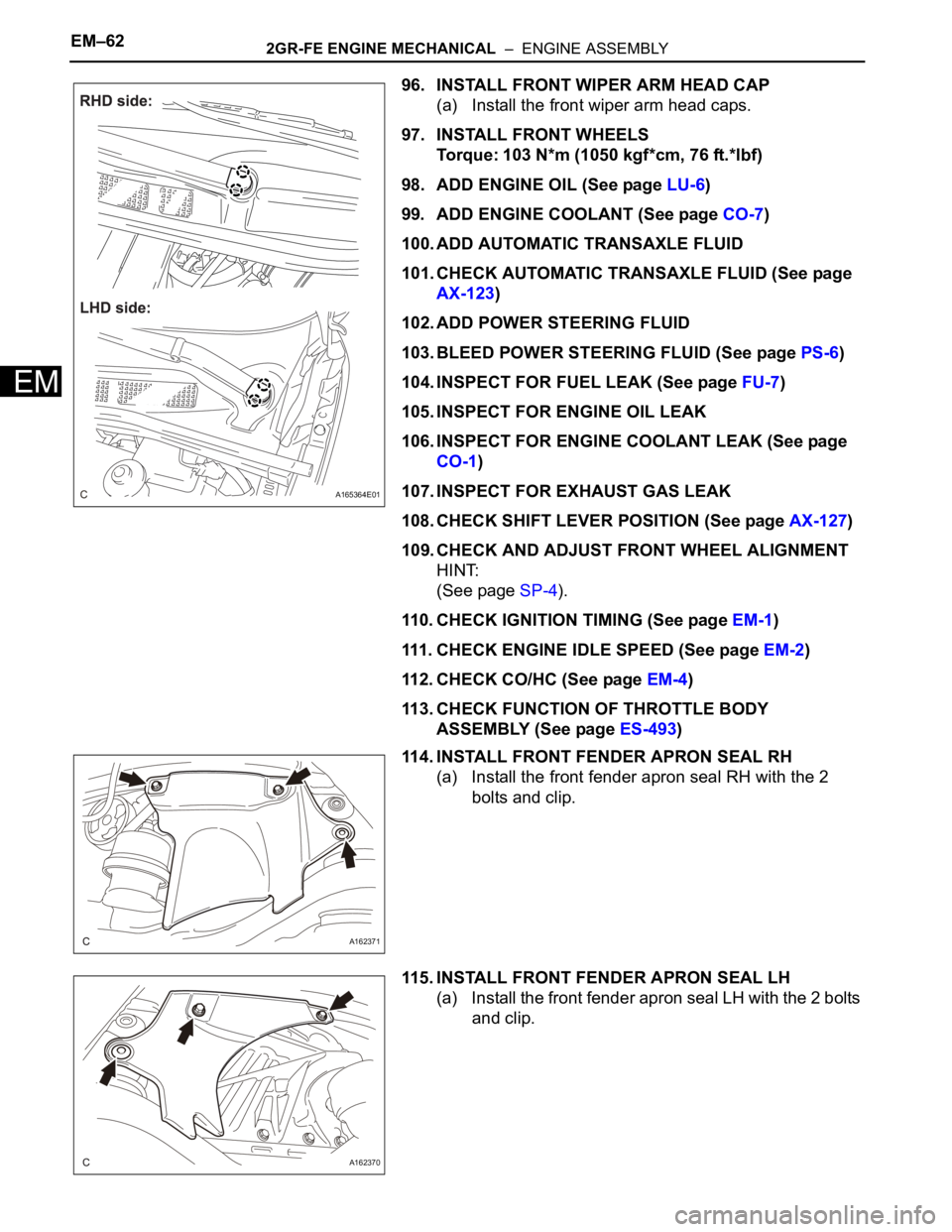
114. INSTALL FRONT FENDER APRON SEAL RH
(a) Install the front fender apron seal RH with the 2
bolts and clip.
115. INSTALL FRONT FENDER APRON SEAL LH
(a) Install the front fender apron seal LH with the 2 bolts
and clip.
A165364E01
A162371
A162370
Page 981 of 3000

2GR-FE ENGINE MECHANICAL – DRIVE BELTEM–7
EM
INSTALLATION
1. INSTALL V-RIBBED BELT
(a) Install the V-ribbed belt.
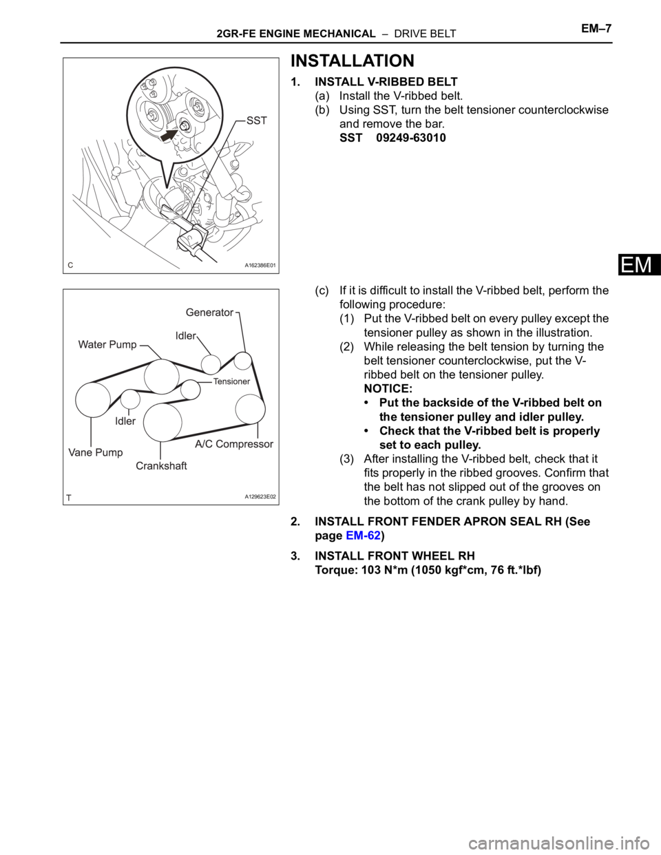
(b) Using SST, turn the belt tensioner counterclockwise
and remove the bar.
SST 09249-63010
(c) If it is difficult to install the V-ribbed belt, perform the
following procedure:
(1) Put the V-ribbed belt on every pulley except the
tensioner pulley as shown in the illustration.
(2) While releasing the belt tension by turning the
belt tensioner counterclockwise, put the V-
ribbed belt on the tensioner pulley.
NOTICE:
• Put the backside of the V-ribbed belt on
the tensioner pulley and idler pulley.
• Check that the V-ribbed belt is properly
set to each pulley.
(3) After installing the V-ribbed belt, check that it
fits properly in the ribbed grooves. Confirm that
the belt has not slipped out of the grooves on
the bottom of the crank pulley by hand.
2. INSTALL FRONT FENDER APRON SEAL RH (See
page EM-62)
3. INSTALL FRONT WHEEL RH
Torque: 103 N*m (1050 kgf*cm, 76 ft.*lbf)
A162386E01
A129623E02