Page 2211 of 3000
SUSPENSION – FRONT LOWER BALL JOINTSP–25
SP
INSTALLATION
1. INSTALL LOWER BALL JOINT ASSEMBLY FRONT
LH
(a) Install the lower ball joint assembly front LH and
tighten the nut.
Torque: 123 N*m (1,250 kgf*cm, 91 ft.*lbf)
(b) Install a new cotter pin.
NOTICE:
If the holes for the cotter pin are not aligned,
tighten the nut further up to 60
.
2. INSTALL FRONT AXLE ASSEMBLY LH
HINT:
(See page AH-4)
3. INSTALL FRONT SUSPENSION ARM SUB-
ASSEMBLY LOWER NO.1 LH
HINT:
(See page AH-4)
4. INSTALL TIE ROD ASSEMBLY LH
HINT:
(See page AH-4)
5. INSTALL FRONT DISC
6. INSTALL FRONT DISC BRAKE CALIPER ASSEMBLY
LH
HINT:
(See page AH-4)
7. INSTALL SPEED SENSOR FRONT LH
HINT:
(See page AH-4)
8. INSTALL FRONT AXLE HUB LH NUT
HINT:
(See page AH-4)
9. INSTALL FRONT WHEEL
Torque: 103 N*m (1,050 kgf*cm, 76 ft.*lbf)
10. INSPECT AND ADJUST FRONT WHEEL ALIGNMENT
HINT:
(See page SP-4)
11. CHECK ABS SPEED SENSOR SIGNAL
w/o VSC: (See page BC-2).
w/ VSC: (See page BC-68).
Page 2230 of 3000

SUSPENSION – REAR COIL SPRINGSP–47
SP
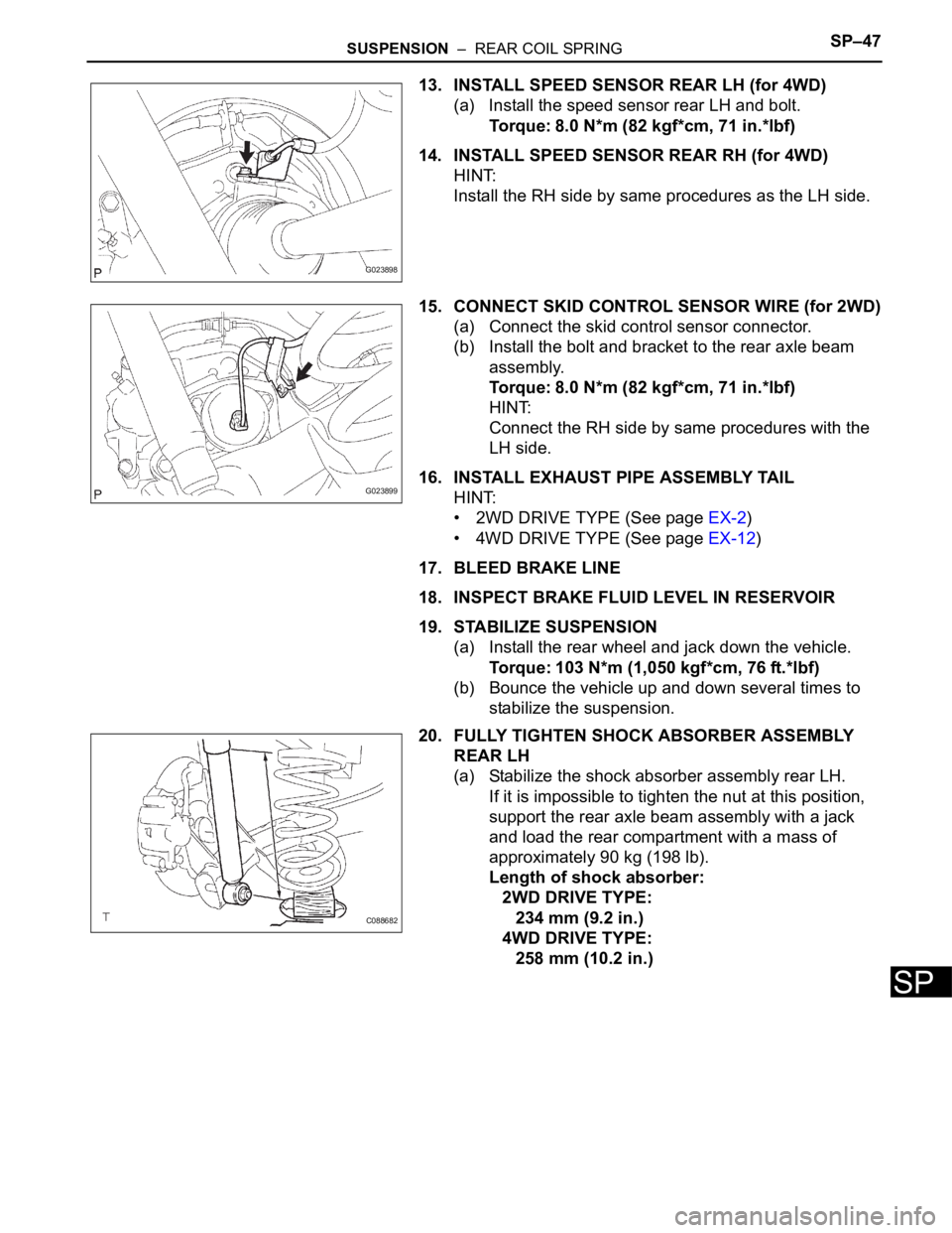
13. INSTALL SPEED SENSOR REAR LH (for 4WD)
(a) Install the speed sensor rear LH and bolt.
Torque: 8.0 N*m (82 kgf*cm, 71 in.*lbf)
14. INSTALL SPEED SENSOR REAR RH (for 4WD)
HINT:
Install the RH side by same procedures as the LH side.
15. CONNECT SKID CONTROL SENSOR WIRE (for 2WD)
(a) Connect the skid control sensor connector.
(b) Install the bolt and bracket to the rear axle beam
assembly.
Torque: 8.0 N*m (82 kgf*cm, 71 in.*lbf)
HINT:
Connect the RH side by same procedures with the
LH side.
16. INSTALL EXHAUST PIPE ASSEMBLY TAIL
HINT:
• 2WD DRIVE TYPE (See page EX-2)
• 4WD DRIVE TYPE (See page EX-12)
17. BLEED BRAKE LINE
18. INSPECT BRAKE FLUID LEVEL IN RESERVOIR
19. STABILIZE SUSPENSION
(a) Install the rear wheel and jack down the vehicle.
Torque: 103 N*m (1,050 kgf*cm, 76 ft.*lbf)
(b) Bounce the vehicle up and down several times to
stabilize the suspension.
20. FULLY TIGHTEN SHOCK ABSORBER ASSEMBLY
REAR LH
(a) Stabilize the shock absorber assembly rear LH.
If it is impossible to tighten the nut at this position,
support the rear axle beam assembly with a jack
and load the rear compartment with a mass of
approximately 90 kg (198 lb).
Length of shock absorber:
2WD DRIVE TYPE:
234 mm (9.2 in.)
4WD DRIVE TYPE:
258 mm (10.2 in.)
G023898
G023899
C088682
Page 2231 of 3000

SP–48SUSPENSION – REAR COIL SPRING
SP
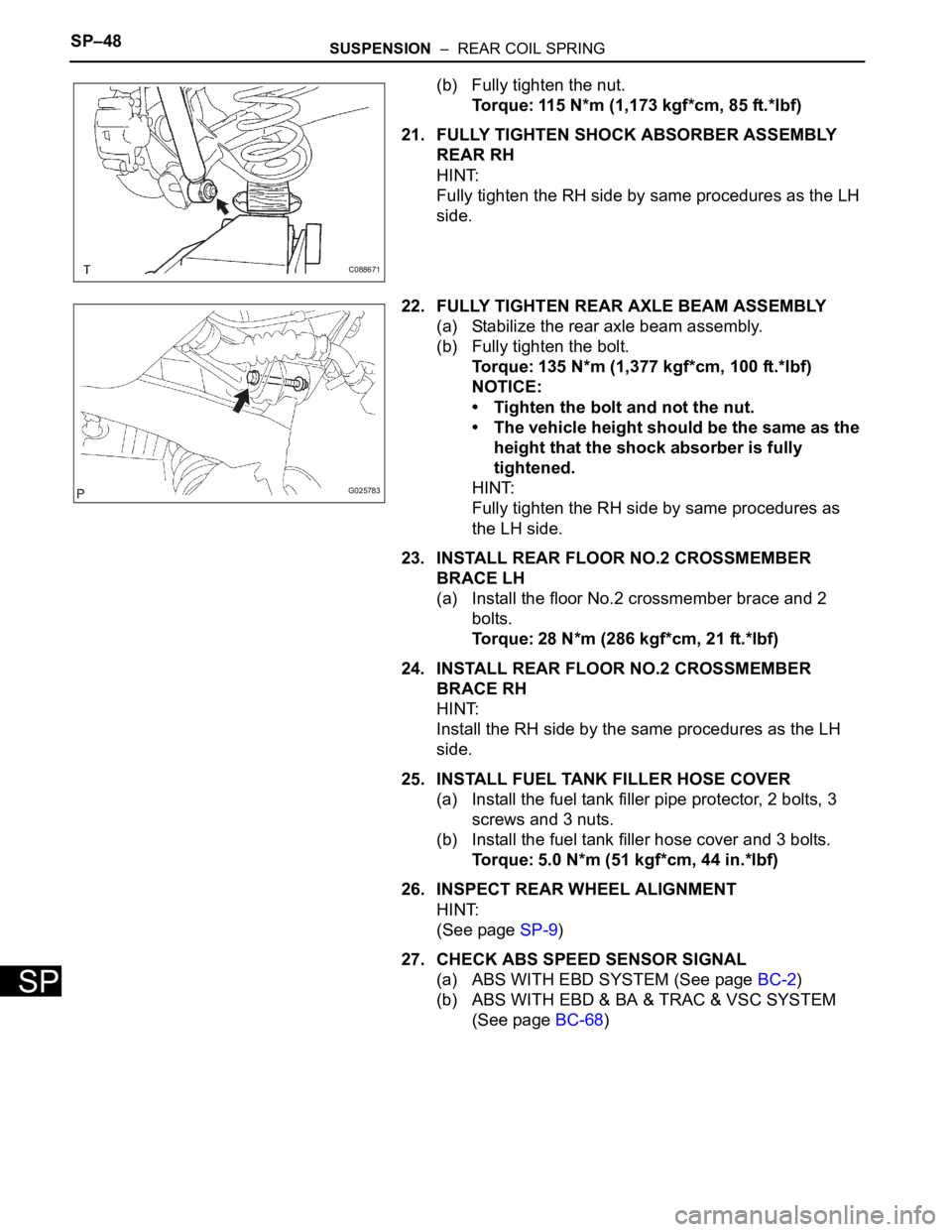
(b) Fully tighten the nut.
Torque: 115 N*m (1,173 kgf*cm, 85 ft.*lbf)
21. FULLY TIGHTEN SHOCK ABSORBER ASSEMBLY
REAR RH
HINT:
Fully tighten the RH side by same procedures as the LH
side.
22. FULLY TIGHTEN REAR AXLE BEAM ASSEMBLY
(a) Stabilize the rear axle beam assembly.
(b) Fully tighten the bolt.
Torque: 135 N*m (1,377 kgf*cm, 100 ft.*lbf)
NOTICE:
• Tighten the bolt and not the nut.
• The vehicle height should be the same as the
height that the shock absorber is fully
tightened.
HINT:
Fully tighten the RH side by same procedures as
the LH side.
23. INSTALL REAR FLOOR NO.2 CROSSMEMBER
BRACE LH
(a) Install the floor No.2 crossmember brace and 2
bolts.
Torque: 28 N*m (286 kgf*cm, 21 ft.*lbf)
24. INSTALL REAR FLOOR NO.2 CROSSMEMBER
BRACE RH
HINT:
Install the RH side by the same procedures as the LH
side.
25. INSTALL FUEL TANK FILLER HOSE COVER
(a) Install the fuel tank filler pipe protector, 2 bolts, 3
screws and 3 nuts.
(b) Install the fuel tank filler hose cover and 3 bolts.
Torque: 5.0 N*m (51 kgf*cm, 44 in.*lbf)
26. INSPECT REAR WHEEL ALIGNMENT
HINT:
(See page SP-9)
27. CHECK ABS SPEED SENSOR SIGNAL
(a) ABS WITH EBD SYSTEM (See page BC-2)
(b) ABS WITH EBD & BA & TRAC & VSC SYSTEM
(See page BC-68)
C088671
G025783
Page 2241 of 3000
SUSPENSION – REAR SHOCK ABSORBERSP–53
SP
(d) Install the rear shock absorber cushion No.1 and
rear shock absorber LH cushion retainer.
(e) Temporary tighten a new lock nut.
(f) Using a 6mm hexagon wrench to hold the piston
rod, fully tighten the lock nut.
Torque: 30 N*m (310 kgf*cm, 22 ft.*lbf)
2. INSTALL REAR SHOCK ABSORBER CAP LH
(a) Install the shock absorber cap LH as shown in the
illustration.
(b) Install the shock absorber head cover.
3. INSTALL REAR WHEEL
Torque: 103 N*m (1,050 kgf*cm, 76 ft.*lbf)
G023897
G023896
G024672
G023895
Page 2242 of 3000
SP–54SUSPENSION – REAR SHOCK ABSORBER
SP
4. FULLY TIGHTEN SHOCK ABSORBER ASSEMBLY
REAR LH
(a) Stabilize the shock absorber assembly rear LH.
If it is impossible to tighten the nut at this position,
support the rear axle beam with a jack and load the
rear compartment with a mass of approximately 90
kg (198 lb).
Length of shock absorber:
2WD DRIVE TYPE:
234 mm (9.22 in.)
4WD DRIVE TYPE:
258 mm (10.16 in.)
(b) Fully tighten the nut.
Torque: 115 N*m (1,173 kgf*cm, 85 ft.*lbf)
5. INSPECT REAR WHEEL ALIGNMENT
HINT:
(See page SP-9)
DISPOSAL
1. DISPOSE OF SHOCK ABSORBER ASSEMBLY REAR
LH
(a) Fully extend the shock absorber rod.
(b) Using a drill, make a hole in the cylinder as shown in
the illustration to discharge the gas inside the
cylinder.
CAUTION:
• When drilling, since the fragments may fly
out, work carefully.
• The discharged gas is colorless, odorless
and non-poisonous.
C088682
C088671
C066544E01
Page 2246 of 3000

SP–64SUSPENSION – REAR AXLE BEAM
SP
32. CONNECT SKID CONTROL SENSOR WIRE (for 2WD)
HINT:
(See page SP-38)
HINT:
Connect the RH side by the same procedures as the LH
side.
33. INSTALL SPEED SENSOR REAR LH (for 4WD)
HINT:
(See page SP-38)
34. INSTALL SPEED SENSOR REAR RH (for 4WD)
HINT:
Install the RH side by the same procedures as the LH
side.
35. INSTALL EXHAUST PIPE ASSEMBLY TAIL
HINT:
• 2WD DRIVE TYPE (See page EX-2)
• 4WD DRIVE TYPE (See page EX-8)
36. BLEED BRAKE LINE
HINT:
(See page BR-3)
37. INSTALL REAR WHEEL
Torque: 103 N*m (1,050 kgf*cm, 76 ft.*lbf)
38. INSPECT BRAKE FLUID LEVEL IN RESERVOIR
39. STABILIZE SUSPENSION
HINT:
(See page SP-52)
40. FULLY TIGHTEN SHOCK ABSORBER ASSEMBLY
REAR LH
HINT:
(See page SP-52)
41. FULLY TIGHTEN SHOCK ABSORBER ASSEMBLY
REAR RH
HINT:
Fully tighten the RH side by the same procedures as the
LH side.
42. FULLY TIGHTEN REAR AXLE BEAM ASSEMBLY
HINT:
(See page SP-38)
43. INSTALL REAR FLOOR NO.2 CROSSMEMBER
BRACE LH
HINT:
(See page SP-38)
44. INSTALL REAR FLOOR NO.2 CROSSMEMBER
BRACE RH
HINT:
Install the RH side by the same procedures as the LH
side.
Page 2331 of 3000
TW–82TIRE AND WHEEL – TIRE PRESSURE WARNING RECEIVER (w/ Antenna)
TW
REMOVAL
1. DISCONNECT CABLE FROM NEGATIVE BATTERY
TERMINAL
2. REMOVE ROOF HEADLINING ASSEMBLY
HINT:
Refer to the instructions for REMOVAL of the ROOF
HEADLINING (See page IR-6).
3. REMOVE TIRE PRESSURE WARNING RECEIVER
ASSEMBLY
(a) Remove the bolt.
(b) Disconnect the connector and remove the tire
pressure warning receiver assembly.
INSTALLATION
1. INSTALL TIRE PRESSURE WARNING RECEIVER
ASSEMBLY
(a) Connect the connector.
(b) Install the tire pressure warning receiver assembly
with the bolt.
Torque: 5.0 N*m (51 kgf*cm, 44 in.*lbf)
2. INSTALL ROOF HEADLINING ASSEMBLY
HINT:
Refer to the instructions for INSTALLATION of the ROOF
HEADLINING (See page IR-14).
3. CONNECT CABLE TO NEGATIVE BATTERY
TERMINAL
4. INSPECT TIRE PRESSURE WARNING SYSTEM
HINT:
See page TW-25.
C156704
C156705
C156705
C156704
Page 2337 of 3000

TIRE AND WHEEL – TIRE PRESSURE WARNING VALVE AND TRANSMITTERTW–85
TW
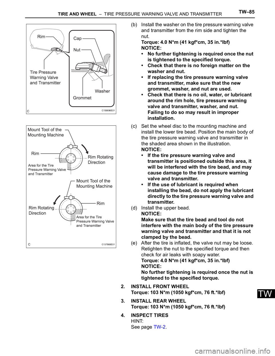
(b) Install the washer on the tire pressure warning valve
and transmitter from the rim side and tighten the
nut.
Torque: 4.0 N*m (41 kgf*cm, 35 in.*lbf)
NOTICE:
• No further tightening is required once the nut
is tightened to the specified torque.
• Check that there is no foreign matter on the
washer and nut.
• If replacing the tire pressure warning valve
and transmitter, make sure that the new
grommet, washer, and nut are used.
• Check that there is no oil, water, or lubricant
around the rim hole, tire pressure warning
valve and transmitter, washer, and nut.
Failing to do so may result in improper
installation.
(c) Set the wheel disc to the mounting machine and
install the lower tire bead. Position the main body of
the tire pressure warning valve and transmitter in
the shaded area shown in the illustration.
NOTICE:
• If the tire pressure warning valve and
transmitter is positioned outside this area, it
will be interfered with the tire bead, and may
cause damage to the tire pressure warning
valve and transmitter.
• If the use of lubricant is required when
installing the bead, do not apply the lubricant
directly to the tire pressure warning valve and
transmitter.
(d) Install the upper bead.
NOTICE:
Make sure that the tire bead and tool do not
interfere with the main body of the tire pressure
warning valve and transmitter and that it is not
clamped by the bead.
(e) After the tire is inflated, the valve nut may be loose.
Retighten the nut to the specified torque and then
check for air leaks with soapy water.
Torque: 4.0 N*m (41 kgf*cm, 35 in.*lbf)
NOTICE:
No further tightening is required once the nut is
tightened to the specified torque.
2. INSTALL FRONT WHEEL
Torque: 103 N*m (1050 kgf*cm, 76 ft.*lbf)
3. INSTALL REAR WHEEL
Torque: 103 N*m (1050 kgf*cm, 76 ft.*lbf)
4. INSPECT TIRES
HINT:
See page TW-2.
C156696E01
C137868E01