Page 2685 of 3000
SR–12STEERING COLUMN – STEERING COLUMN ASSEMBLY
SR
7. INSTALL STEERING WHEEL ASSEMBLY
(a) Align the matchmarks on the steering wheel
assembly and steering main shaft assembly.
(b) Install the steering wheel assembly set nut.
Torque: 50 N*m (510 kgf*cm, 37 ft.*lbf)
(c) Connect the connector.
8. INSPECT STEERING WHEEL CENTER POINT
9. INSPECT HORN BUTTON ASSEMBLY (See page RS-
425)
10. INSTALL HORN BUTTON ASSEMBLY (See page RS-
424)
11. INSTALL STEERING WHEEL COVER LOWER NO.3
(See page RS-425)
12. INSTALL STEERING WHEEL COVER LOWER NO.2
(See page RS-425)
13. CONNECT BATTERY NEGATIVE TERMINAL
14. INSPECT SRS WARNING LIGHT (See page RS-436)
Page 2691 of 3000
PS–20POWER STEERING – VANE PUMP
PS
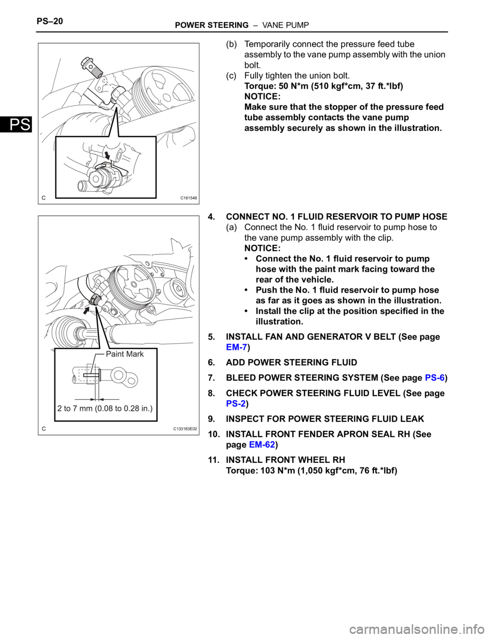
(b) Temporarily connect the pressure feed tube
assembly to the vane pump assembly with the union
bolt.
(c) Fully tighten the union bolt.
Torque: 50 N*m (510 kgf*cm, 37 ft.*lbf)
NOTICE:
Make sure that the stopper of the pressure feed
tube assembly contacts the vane pump
assembly securely as shown in the illustration.
4. CONNECT NO. 1 FLUID RESERVOIR TO PUMP HOSE
(a) Connect the No. 1 fluid reservoir to pump hose to
the vane pump assembly with the clip.
NOTICE:
• Connect the No. 1 fluid reservoir to pump
hose with the paint mark facing toward the
rear of the vehicle.
• Push the No. 1 fluid reservoir to pump hose
as far as it goes as shown in the illustration.
• Install the clip at the position specified in the
illustration.
5. INSTALL FAN AND GENERATOR V BELT (See page
EM-7)
6. ADD POWER STEERING FLUID
7. BLEED POWER STEERING SYSTEM (See page PS-6)
8. CHECK POWER STEERING FLUID LEVEL (See page
PS-2)
9. INSPECT FOR POWER STEERING FLUID LEAK
10. INSTALL FRONT FENDER APRON SEAL RH (See
page EM-62)
11. INSTALL FRONT WHEEL RH
Torque: 103 N*m (1,050 kgf*cm, 76 ft.*lbf)
C161548
C133183E02
Page 2706 of 3000
PS–38POWER STEERING – RACK AND PINION POWER STEERING GEAR
PS
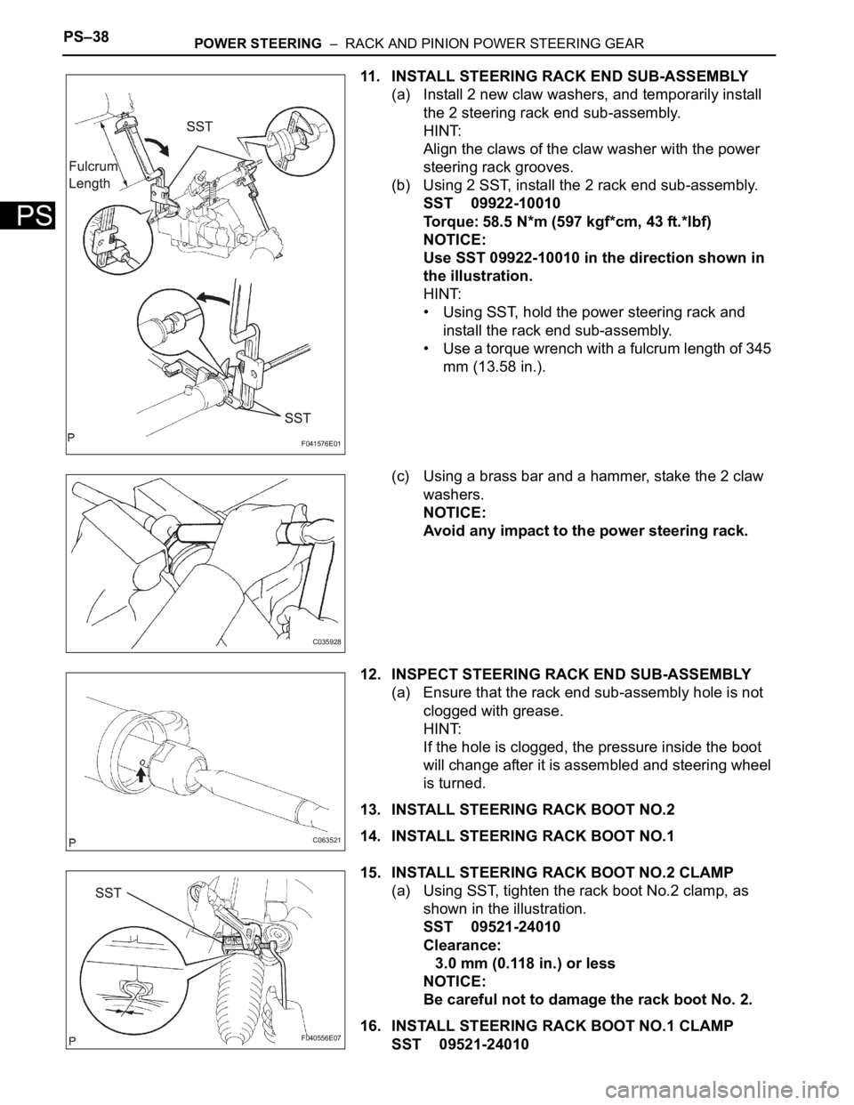
11. INSTALL STEERING RACK END SUB-ASSEMBLY
(a) Install 2 new claw washers, and temporarily install
the 2 steering rack end sub-assembly.
HINT:
Align the claws of the claw washer with the power
steering rack grooves.
(b) Using 2 SST, install the 2 rack end sub-assembly.
SST 09922-10010
Torque: 58.5 N*m (597 kgf*cm, 43 ft.*lbf)
NOTICE:
Use SST 09922-10010 in the direction shown in
the illustration.
HINT:
• Using SST, hold the power steering rack and
install the rack end sub-assembly.
• Use a torque wrench with a fulcrum length of 345
mm (13.58 in.).
(c) Using a brass bar and a hammer, stake the 2 claw
washers.
NOTICE:
Avoid any impact to the power steering rack.
12. INSPECT STEERING RACK END SUB-ASSEMBLY
(a) Ensure that the rack end sub-assembly hole is not
clogged with grease.
HINT:
If the hole is clogged, the pressure inside the boot
will change after it is assembled and steering wheel
is turned.
13. INSTALL STEERING RACK BOOT NO.2
14. INSTALL STEERING RACK BOOT NO.1
15. INSTALL STEERING RACK BOOT NO.2 CLAMP
(a) Using SST, tighten the rack boot No.2 clamp, as
shown in the illustration.
SST 09521-24010
Clearance:
3.0 mm (0.118 in.) or less
NOTICE:
Be careful not to damage the rack boot No. 2.
16. INSTALL STEERING RACK BOOT NO.1 CLAMP
SST 09521-24010
F041576E01
C035928
C063521
F040556E07
Page 2709 of 3000
POWER STEERING – RACK AND PINION POWER STEERING GEARPS–41
PS
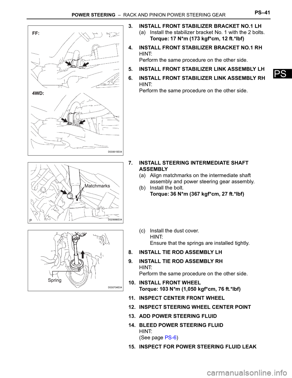
3. INSTALL FRONT STABILIZER BRACKET NO.1 LH
(a) Install the stabilizer bracket No. 1 with the 2 bolts.
Torque: 17 N*m (173 kgf*cm, 12 ft.*lbf)
4. INSTALL FRONT STABILIZER BRACKET NO.1 RH
HINT:
Perform the same procedure on the other side.
5. INSTALL FRONT STABILIZER LINK ASSEMBLY LH
6. INSTALL FRONT STABILIZER LINK ASSEMBLY RH
HINT:
Perform the same procedure on the other side.
7. INSTALL STEERING INTERMEDIATE SHAFT
ASSEMBLY
(a) Align matchmarks on the intermediate shaft
assembly and power steering gear assembly.
(b) Install the bolt.
Torque: 36 N*m (367 kgf*cm, 27 ft.*lbf)
(c) Install the dust cover.
HINT:
Ensure that the springs are installed tightly.
8. INSTALL TIE ROD ASSEMBLY LH
9. INSTALL TIE ROD ASSEMBLY RH
HINT:
Perform the same procedure on the other side.
10. INSTALL FRONT WHEEL
Torque: 103 N*m (1,050 kgf*cm, 76 ft.*lbf)
11. INSPECT CENTER FRONT WHEEL
12. INSPECT STEERING WHEEL CENTER POINT
13. ADD POWER STEERING FLUID
14. BLEED POWER STEERING FLUID
HINT:
(See page PS-6)
15. INSPECT FOR POWER STEERING FLUID LEAK
D030615E04
D029986E04
D030704E04
Page 2715 of 3000
POWER STEERING – POWER STEERING SYSTEMPS–5
PS
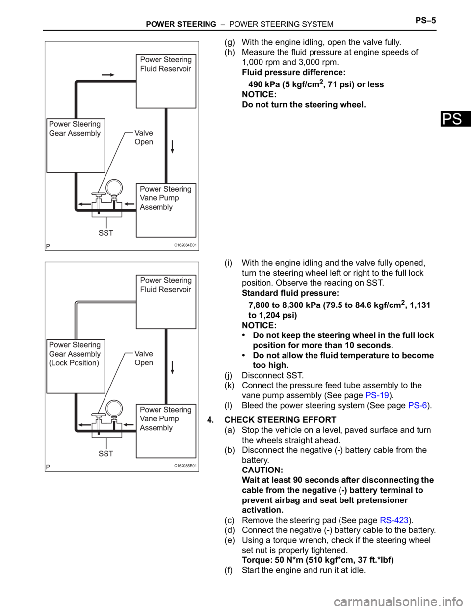
(g) With the engine idling, open the valve fully.
(h) Measure the fluid pressure at engine speeds of
1,000 rpm and 3,000 rpm.
Fluid pressure difference:
490 kPa (5 kgf/cm
2, 71 psi) or less
NOTICE:
Do not turn the steering wheel.
(i) With the engine idling and the valve fully opened,
turn the steering wheel left or right to the full lock
position. Observe the reading on SST.
Standard fluid pressure:
7,800 to 8,300 kPa (79.5 to 84.6 kgf/cm
2, 1,131
to 1,204 psi)
NOTICE:
• Do not keep the steering wheel in the full lock
position for more than 10 seconds.
• Do not allow the fluid temperature to become
too high.
(j) Disconnect SST.
(k) Connect the pressure feed tube assembly to the
vane pump assembly (See page PS-19).
(l) Bleed the power steering system (See page PS-6).
4. CHECK STEERING EFFORT
(a) Stop the vehicle on a level, paved surface and turn
the wheels straight ahead.
(b) Disconnect the negative (-) battery cable from the
battery.
CAUTION:
Wait at least 90 seconds after disconnecting the
cable from the negative (-) battery terminal to
prevent airbag and seat belt pretensioner
activation.
(c) Remove the steering pad (See page RS-423).
(d) Connect the negative (-) battery cable to the battery.
(e) Using a torque wrench, check if the steering wheel
set nut is properly tightened.
Torque: 50 N*m (510 kgf*cm, 37 ft.*lbf)
(f) Start the engine and run it at idle.
C162084E01
C162085E01
Page 2716 of 3000
PS–6POWER STEERING – POWER STEERING SYSTEM
PS
(g) Turn the steering wheel 90 degrees to the right and
check steering effort (torque) while turning the
wheel. Check the opposite direction in the same
manner.
Torque: Steering effort (Reference)
6.0 N*m (61 kgf*cm, 53 in.*lbf)
HINT:
Check the tire type, pressure, and the road surface
before making your diagnosis.
(h) Disconnect the negative (-) battery cable from the
battery.
(i) Tighten the steering wheel set nut.
Torque: 50 N*m (510 kgf*cm, 37 ft.*lbf)
(j) Install the steering pad (See page RS-424).
(k) Connect the negative (-) battery cable to the battery.
(l) Clear the DTCs (See page RS-35).
(m) Inspect the airbag warning light (See page RS-27).
F041590
Page 2731 of 3000
PS–20POWER STEERING – VANE PUMP
PS
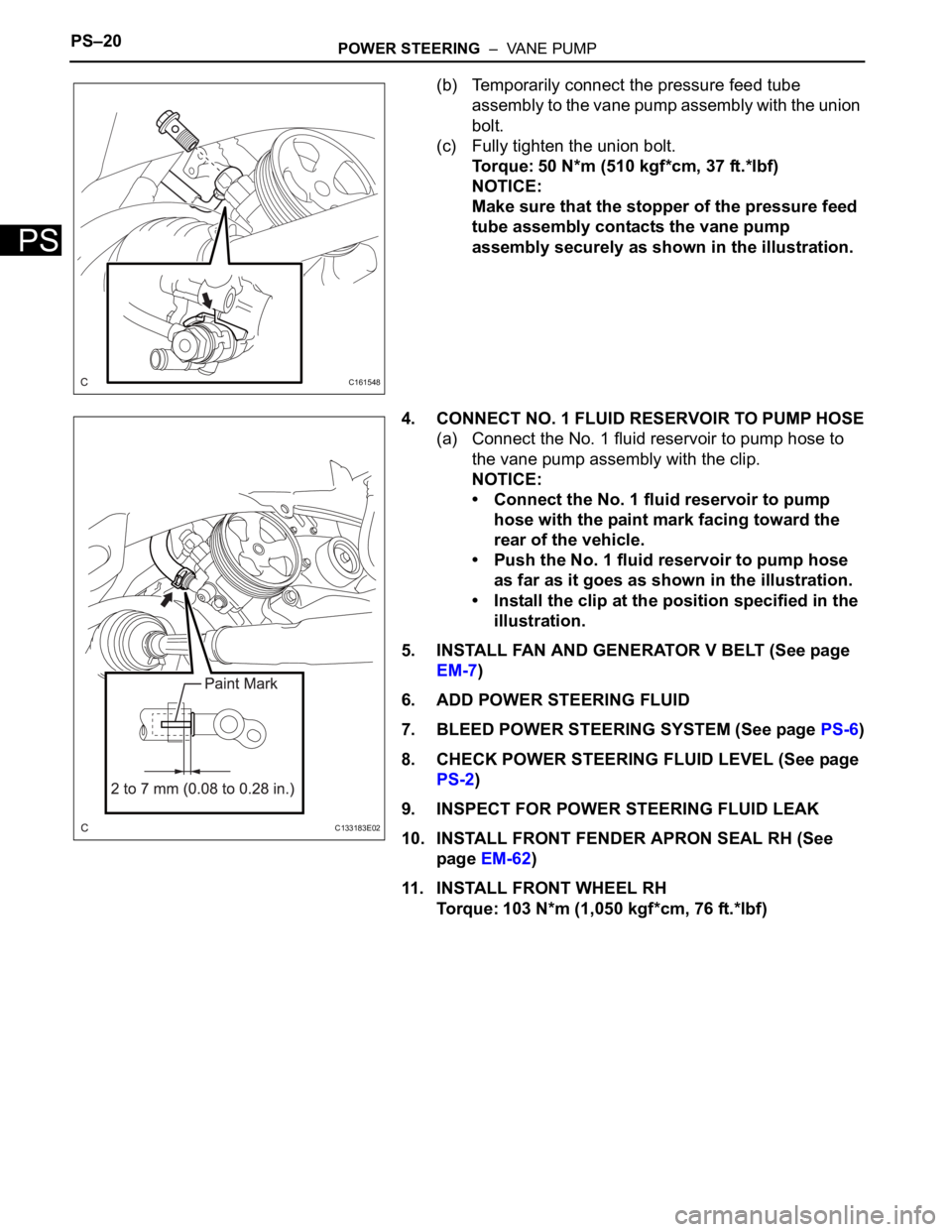
(b) Temporarily connect the pressure feed tube
assembly to the vane pump assembly with the union
bolt.
(c) Fully tighten the union bolt.
Torque: 50 N*m (510 kgf*cm, 37 ft.*lbf)
NOTICE:
Make sure that the stopper of the pressure feed
tube assembly contacts the vane pump
assembly securely as shown in the illustration.
4. CONNECT NO. 1 FLUID RESERVOIR TO PUMP HOSE
(a) Connect the No. 1 fluid reservoir to pump hose to
the vane pump assembly with the clip.
NOTICE:
• Connect the No. 1 fluid reservoir to pump
hose with the paint mark facing toward the
rear of the vehicle.
• Push the No. 1 fluid reservoir to pump hose
as far as it goes as shown in the illustration.
• Install the clip at the position specified in the
illustration.
5. INSTALL FAN AND GENERATOR V BELT (See page
EM-7)
6. ADD POWER STEERING FLUID
7. BLEED POWER STEERING SYSTEM (See page PS-6)
8. CHECK POWER STEERING FLUID LEVEL (See page
PS-2)
9. INSPECT FOR POWER STEERING FLUID LEAK
10. INSTALL FRONT FENDER APRON SEAL RH (See
page EM-62)
11. INSTALL FRONT WHEEL RH
Torque: 103 N*m (1,050 kgf*cm, 76 ft.*lbf)
C161548
C133183E02
Page 2749 of 3000
PS–38POWER STEERING – RACK AND PINION POWER STEERING GEAR
PS
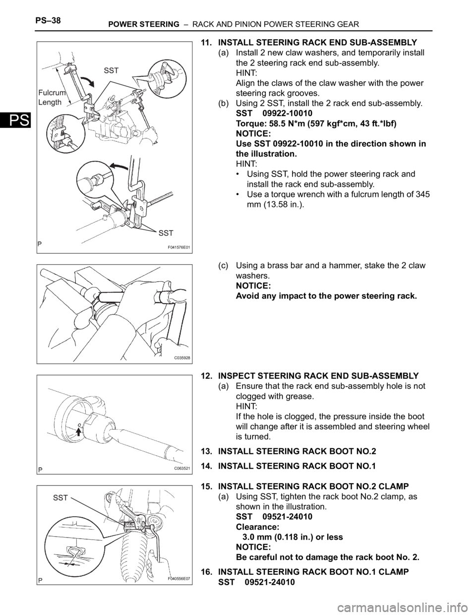
11. INSTALL STEERING RACK END SUB-ASSEMBLY
(a) Install 2 new claw washers, and temporarily install
the 2 steering rack end sub-assembly.
HINT:
Align the claws of the claw washer with the power
steering rack grooves.
(b) Using 2 SST, install the 2 rack end sub-assembly.
SST 09922-10010
Torque: 58.5 N*m (597 kgf*cm, 43 ft.*lbf)
NOTICE:
Use SST 09922-10010 in the direction shown in
the illustration.
HINT:
• Using SST, hold the power steering rack and
install the rack end sub-assembly.
• Use a torque wrench with a fulcrum length of 345
mm (13.58 in.).
(c) Using a brass bar and a hammer, stake the 2 claw
washers.
NOTICE:
Avoid any impact to the power steering rack.
12. INSPECT STEERING RACK END SUB-ASSEMBLY
(a) Ensure that the rack end sub-assembly hole is not
clogged with grease.
HINT:
If the hole is clogged, the pressure inside the boot
will change after it is assembled and steering wheel
is turned.
13. INSTALL STEERING RACK BOOT NO.2
14. INSTALL STEERING RACK BOOT NO.1
15. INSTALL STEERING RACK BOOT NO.2 CLAMP
(a) Using SST, tighten the rack boot No.2 clamp, as
shown in the illustration.
SST 09521-24010
Clearance:
3.0 mm (0.118 in.) or less
NOTICE:
Be careful not to damage the rack boot No. 2.
16. INSTALL STEERING RACK BOOT NO.1 CLAMP
SST 09521-24010
F041576E01
C035928
C063521
F040556E07