Page 555 of 3000
2GR-FE ENGINE CONTROL SYSTEM – SFI SYSTEMES–249
ES
OK
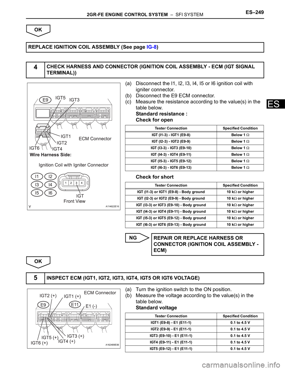
(a) Disconnect the I1, I2, I3, I4, I5 or I6 ignition coil with
igniter connector.
(b) Disconnect the E9 ECM connector.
(c) Measure the resistance according to the value(s) in the
table below.
Standard resistance :
Check for open
Check for short
NG
OK
(a) Turn the ignition switch to the ON position.
(b) Measure the voltage according to the value(s) in the
table below.
Standard voltage REPLACE IGNITION COIL ASSEMBLY (See page IG-8)
4CHECK HARNESS AND CONNECTOR (IGNITION COIL ASSEMBLY - ECM (IGT SIGNAL
TERMINAL))
A114622E16
Tester Connection Specified Condition
IGT (I1-3) - IGT1 (E9-8) Below 1
IGT (I2-3) - IGT2 (E9-9) Below 1
IGT (I3-3) - IGT3 (E9-10) Below 1
IGT (I4-3) - IGT4 (E9-11) Below 1
IGT (I5-3) - IGT5 (E9-12) Below 1
IGT (I6-3) - IGT6 (E9-13) Below 1
Tester Connection Specified Condition
IGT (I1-3) or IGT1 (E9-8) - Body ground 10 k
or higher
IGT (I2-3) or IGT2 (E9-9) - Body ground 10 k
or higher
IGT (I3-3) or IGT3 (E9-10) - Body ground 10 k
or higher
IGT (I4-3) or IGT4 (E9-11) - Body ground 10 k
or higher
IGT (I5-3) or IGT5 (E9-12) - Body ground 10 k
or higher
IGT (I6-3) or IGT6 (E9-13) - Body ground 10 k
or higher
REPAIR OR REPLACE HARNESS OR
CONNECTOR (IGNITION COIL ASSEMBLY -
ECM)
5INSPECT ECM (IGT1, IGT2, IGT3, IGT4, IGT5 OR IGT6 VOLTAGE)
A162489E06
Tester Connection Specified Condition
IGT1 (E9-8) - E1 (E11-1) 0.1 to 4.5 V
IGT2 (E9-9) - E1 (E11-1) 0.1 to 4.5 V
IGT3 (E9-10) - E1 (E11-1) 0.1 to 4.5 V
IGT4 (E9-11) - E1 (E11-1) 0.1 to 4.5 V
IGT5 (E9-12) - E1 (E11-1) 0.1 to 4.5 V
Page 556 of 3000
ES–2502GR-FE ENGINE CONTROL SYSTEM – SFI SYSTEM
ES
NG
OK
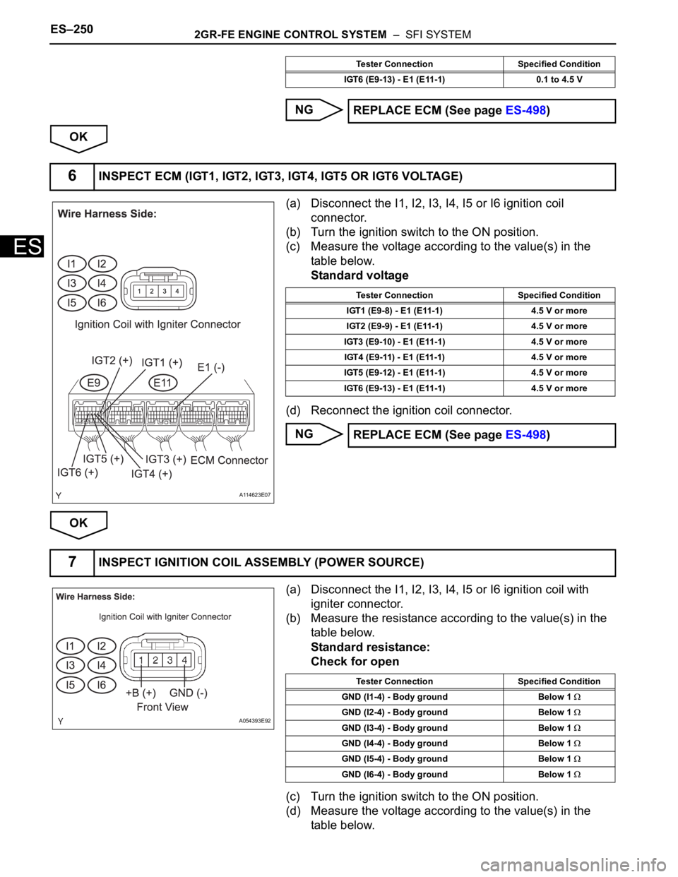
(a) Disconnect the I1, I2, I3, I4, I5 or I6 ignition coil
connector.
(b) Turn the ignition switch to the ON position.
(c) Measure the voltage according to the value(s) in the
table below.
Standard voltage
(d) Reconnect the ignition coil connector.
NG
OK
(a) Disconnect the I1, I2, I3, I4, I5 or I6 ignition coil with
igniter connector.
(b) Measure the resistance according to the value(s) in the
table below.
Standard resistance:
Check for open
(c) Turn the ignition switch to the ON position.
(d) Measure the voltage according to the value(s) in the
table below.
IGT6 (E9-13) - E1 (E11-1) 0.1 to 4.5 V
REPLACE ECM (See page ES-498)
Tester Connection Specified Condition
6INSPECT ECM (IGT1, IGT2, IGT3, IGT4, IGT5 OR IGT6 VOLTAGE)
A114623E07
Tester Connection Specified Condition
IGT1 (E9-8) - E1 (E11-1) 4.5 V or more
IGT2 (E9-9) - E1 (E11-1) 4.5 V or more
IGT3 (E9-10) - E1 (E11-1) 4.5 V or more
IGT4 (E9-11) - E1 (E11-1) 4.5 V or more
IGT5 (E9-12) - E1 (E11-1) 4.5 V or more
IGT6 (E9-13) - E1 (E11-1) 4.5 V or more
REPLACE ECM (See page ES-498)
7INSPECT IGNITION COIL ASSEMBLY (POWER SOURCE)
A054393E92
Tester Connection Specified Condition
GND (I1-4) - Body ground Below 1
GND (I2-4) - Body ground Below 1
GND (I3-4) - Body ground Below 1
GND (I4-4) - Body ground Below 1
GND (I5-4) - Body ground Below 1
GND (I6-4) - Body ground Below 1
Page 557 of 3000
2GR-FE ENGINE CONTROL SYSTEM – SFI SYSTEMES–251
ES
Standard voltage
(e) Reconnect the ignition coil with igniter connector.
NG
OK
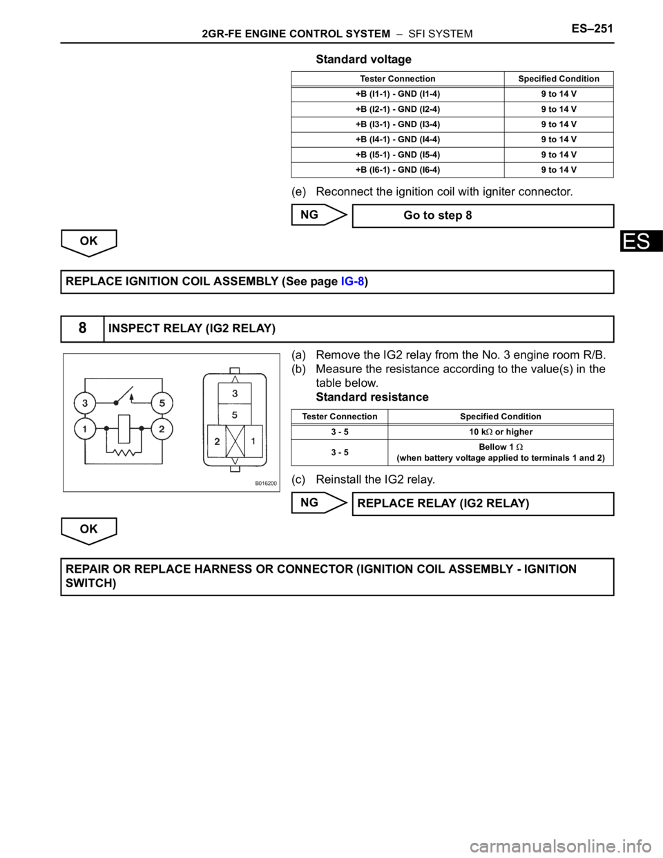
(a) Remove the IG2 relay from the No. 3 engine room R/B.
(b) Measure the resistance according to the value(s) in the
table below.
Standard resistance
(c) Reinstall the IG2 relay.
NG
OK
Tester Connection Specified Condition
+B (I1-1) - GND (I1-4) 9 to 14 V
+B (I2-1) - GND (I2-4) 9 to 14 V
+B (I3-1) - GND (I3-4) 9 to 14 V
+B (I4-1) - GND (I4-4) 9 to 14 V
+B (I5-1) - GND (I5-4) 9 to 14 V
+B (I6-1) - GND (I6-4) 9 to 14 V
Go to step 8
REPLACE IGNITION COIL ASSEMBLY (See page IG-8)
8INSPECT RELAY (IG2 RELAY)
B016200
Tester Connection Specified Condition
3 - 5 10 k
or higher
3 - 5Bellow 1
(when battery voltage applied to terminals 1 and 2)
REPLACE RELAY (IG2 RELAY)
REPAIR OR REPLACE HARNESS OR CONNECTOR (IGNITION COIL ASSEMBLY - IGNITION
SWITCH)
Page 576 of 3000
2GR-FE ENGINE CONTROL SYSTEM – SFI SYSTEMES–283
ES
B
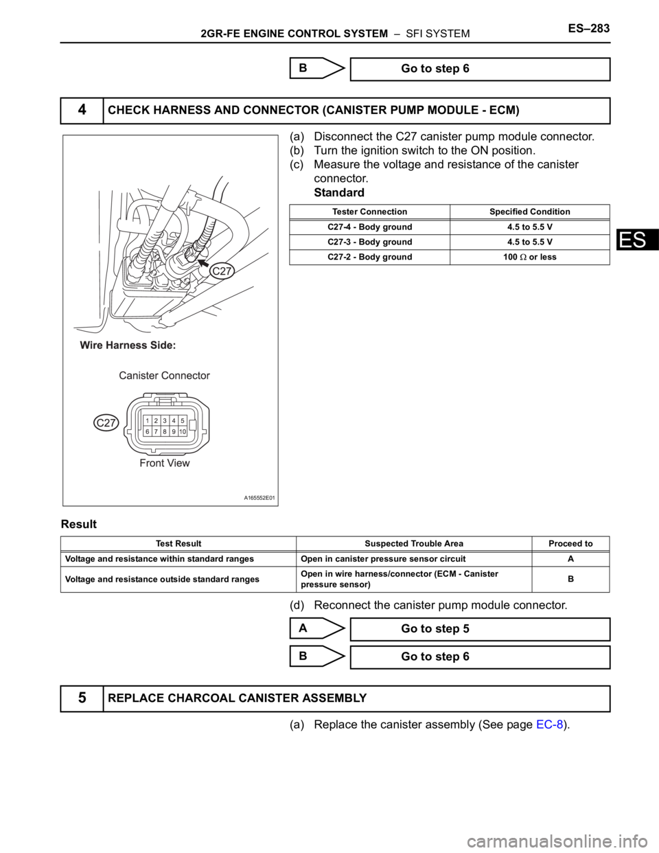
(a) Disconnect the C27 canister pump module connector.
(b) Turn the ignition switch to the ON position.
(c) Measure the voltage and resistance of the canister
connector.
Standard
Result
(d) Reconnect the canister pump module connector.
A
B
(a) Replace the canister assembly (See page EC-8). Go to step 6
4CHECK HARNESS AND CONNECTOR (CANISTER PUMP MODULE - ECM)
A165552E01
Tester Connection Specified Condition
C27-4 - Body ground 4.5 to 5.5 V
C27-3 - Body ground 4.5 to 5.5 V
C27-2 - Body ground 100
or less
Test Result Suspected Trouble Area Proceed to
Voltage and resistance within standard ranges Open in canister pressure sensor circuit A
Voltage and resistance outside standard rangesOpen in wire harness/connector (ECM - Canister
pressure sensor)B
Go to step 5
Go to step 6
5REPLACE CHARCOAL CANISTER ASSEMBLY
Page 586 of 3000
2GR-FE ENGINE CONTROL SYSTEM – SFI SYSTEMES–293
ES
(a) Drive the vehicle and check whether the operation of the
speedometer in the combination meter is normal.
HINT:
• The vehicle speed sensor is operating normally if the
speedometer reading is normal.
• If the speedometer does not operate, check it by
following the procedure described in speedometer
malfunction.
NG
OK
(a) Connect the intelligent tester to the DLC3.
(b) Turn the ignition switch to the ON position.
(c) Turn the tester on.
(d) Select the following menu items: DIAGNOSIS /
ENHANCED OBD II / DATA LIST / PRIMARY / VEHICLE
SPD.
(e) Drive the vehicle.
(f) Read the value displayed on the tester.
OK:
Vehicle speeds displayed on tester and
speedometer display are equal.
NG
OK
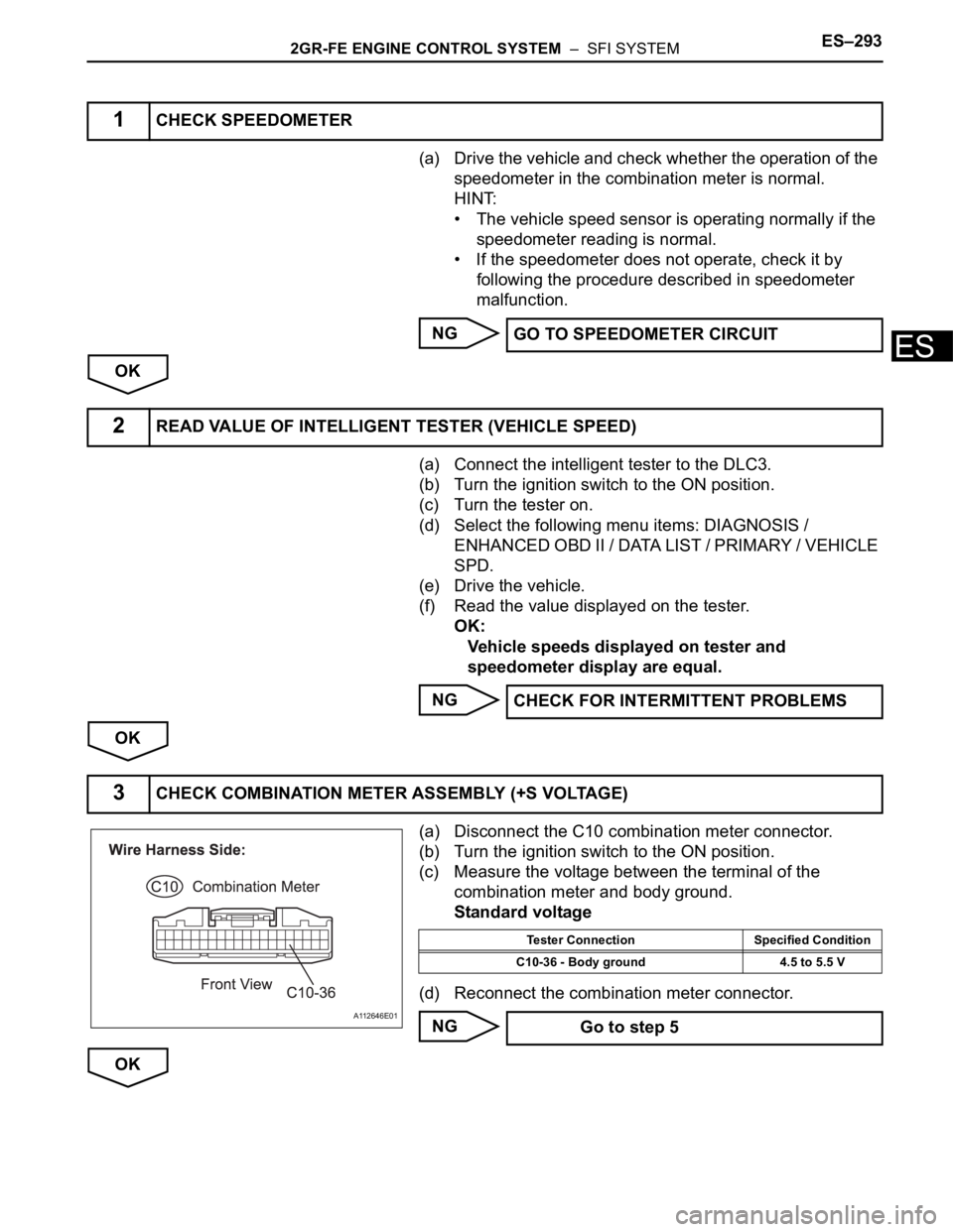
(a) Disconnect the C10 combination meter connector.
(b) Turn the ignition switch to the ON position.
(c) Measure the voltage between the terminal of the
combination meter and body ground.
Standard voltage
(d) Reconnect the combination meter connector.
NG
OK
1CHECK SPEEDOMETER
GO TO SPEEDOMETER CIRCUIT
2READ VALUE OF INTELLIGENT TESTER (VEHICLE SPEED)
CHECK FOR INTERMITTENT PROBLEMS
3CHECK COMBINATION METER ASSEMBLY (+S VOLTAGE)
A112646E01
Tester Connection Specified Condition
C10-36 - Body ground 4.5 to 5.5 V
Go to step 5
Page 587 of 3000
ES–2942GR-FE ENGINE CONTROL SYSTEM – SFI SYSTEM
ES
(a) Shift the transmission gear selector lever to the neutral
position.
(b) Jack up the vehicle.
(c) Turn the ignition switch to the ON position.
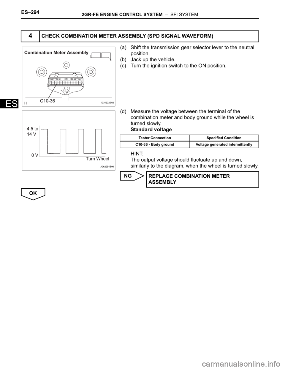
(d) Measure the voltage between the terminal of the
combination meter and body ground while the wheel is
turned slowly.
Standard voltage
HINT:
The output voltage should fluctuate up and down,
similarly to the diagram, when the wheel is turned slowly.
NG
OK
4CHECK COMBINATION METER ASSEMBLY (SPD SIGNAL WAVEFORM)
I034622E02
A062954E06
Tester Connection Specified Condition
C10-36 - Body ground Voltage generated intermittently
REPLACE COMBINATION METER
ASSEMBLY
Page 588 of 3000
2GR-FE ENGINE CONTROL SYSTEM – SFI SYSTEMES–295
ES
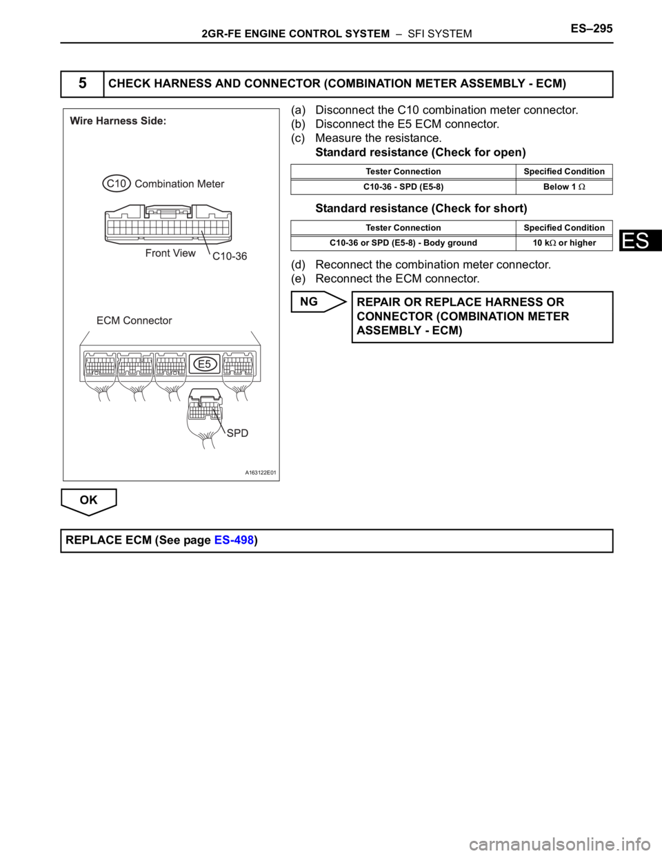
(a) Disconnect the C10 combination meter connector.
(b) Disconnect the E5 ECM connector.
(c) Measure the resistance.
Standard resistance (Check for open)
Standard resistance (Check for short)
(d) Reconnect the combination meter connector.
(e) Reconnect the ECM connector.
NG
OK
5CHECK HARNESS AND CONNECTOR (COMBINATION METER ASSEMBLY - ECM)
A163122E01
Tester Connection Specified Condition
C10-36 - SPD (E5-8) Below 1
Tester Connection Specified Condition
C10-36 or SPD (E5-8) - Body ground 10 k
or higher
REPAIR OR REPLACE HARNESS OR
CONNECTOR (COMBINATION METER
ASSEMBLY - ECM)
REPLACE ECM (See page ES-498)
Page 591 of 3000
ES–2982GR-FE ENGINE CONTROL SYSTEM – SFI SYSTEM
ES
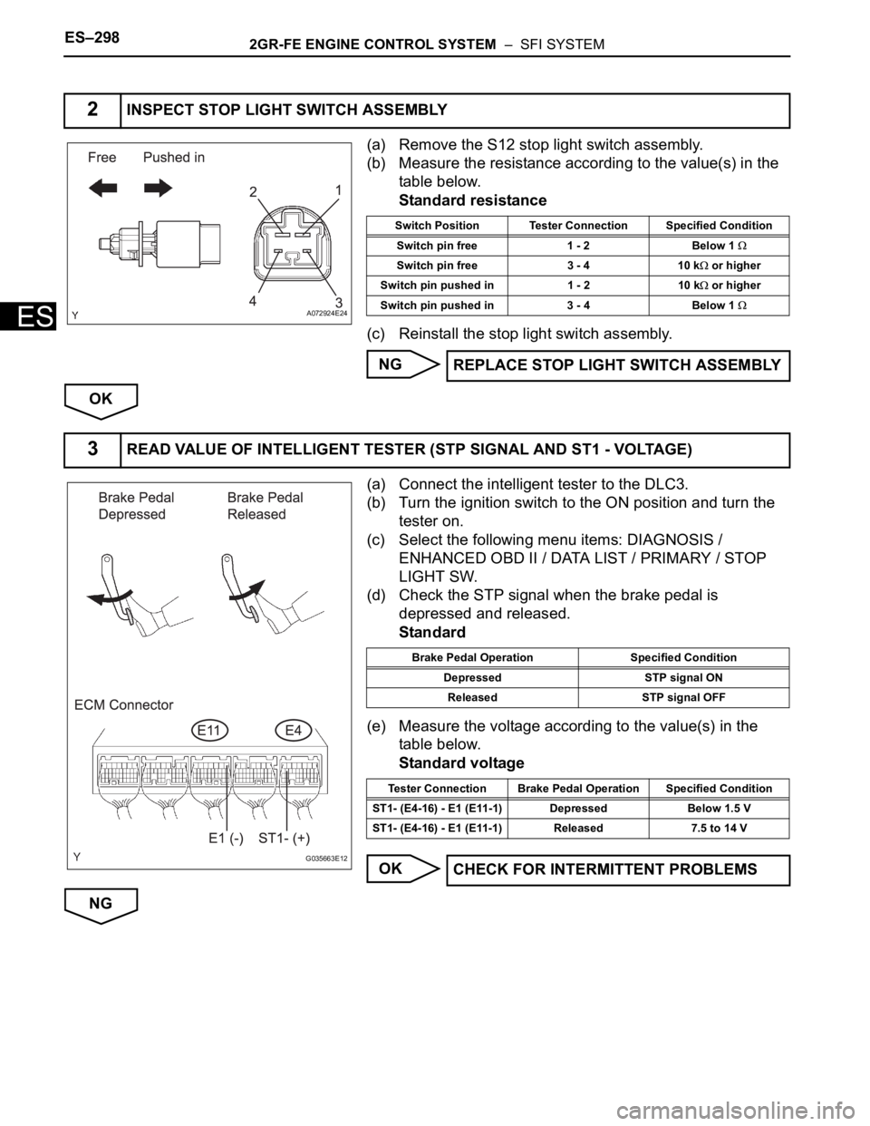
(a) Remove the S12 stop light switch assembly.
(b) Measure the resistance according to the value(s) in the
table below.
Standard resistance
(c) Reinstall the stop light switch assembly.
NG
OK
(a) Connect the intelligent tester to the DLC3.
(b) Turn the ignition switch to the ON position and turn the
tester on.
(c) Select the following menu items: DIAGNOSIS /
ENHANCED OBD II / DATA LIST / PRIMARY / STOP
LIGHT SW.
(d) Check the STP signal when the brake pedal is
depressed and released.
Standard
(e) Measure the voltage according to the value(s) in the
table below.
Standard voltage
OK
NG
2INSPECT STOP LIGHT SWITCH ASSEMBLY
A072924E24
Switch Position Tester Connection Specified Condition
Switch pin free 1 - 2 Below 1
Switch pin free 3 - 4 10 k or higher
Switch pin pushed in 1 - 2 10 k
or higher
Switch pin pushed in 3 - 4 Below 1
REPLACE STOP LIGHT SWITCH ASSEMBLY
3READ VALUE OF INTELLIGENT TESTER (STP SIGNAL AND ST1 - VOLTAGE)
G035663E12
Brake Pedal Operation Specified Condition
Depressed STP signal ON
Released STP signal OFF
Tester Connection Brake Pedal Operation Specified Condition
ST1- (E4-16) - E1 (E11-1) Depressed Below 1.5 V
ST1- (E4-16) - E1 (E11-1) Released 7.5 to 14 V
CHECK FOR INTERMITTENT PROBLEMS