Page 501 of 3000

2GR-FE ENGINE CONTROL SYSTEM – SFI SYSTEMES–195
ES
Between 7.4 g/s and 18.9 g/s (shift position: N, A/
C: OFF).
NG
OK
(a) Check the fuel pressure (See page FU-7).
NG
OK
OK:
No gas leakage.
NG
OK
(a) Check for sparks and ignition (See page ES-217).
HINT:
If the spark plugs or ignition system malfunctions, engine
misfire may occur. The misfire count can be read using
the intelligent tester. Select the following menu items:
DIAGNOSIS / ENHANCED OBD II / DATA LIST /
PRIMARY / CYL #1 (to CYL #6).
NG
OK
(a) Inspect the fuel injector assembly (See page FU-16).
HINT:
If the injectors malfunction, engine misfire may occur.
The misfire count can be read using the intelligent tester.
Select the following menu items: DIAGNOSIS /
ENHANCED OBD II / DATA LIST / PRIMARY / CYL #1
(to CYL #6).
NG
OKREPLACE MASS AIR FLOW METER (See
page ES-504)
7CHECK FUEL PRESSURE
REPAIR OR REPLACE FUEL SYSTEM
8INSPECT FOR EXHAUST GAS LEAK
REPAIR OR REPLACE EXHAUST SYSTEM
9CHECK FOR SPARKS AND IGNITION
REPAIR OR REPLACE IGNITION SYSTEM
10INSPECT FUEL INJECTOR ASSEMBLY (INJECTION AND VOLUME)
REPLACE FUEL INJECTOR ASSEMBLY (See
page FU-13)
Page 517 of 3000
2GR-FE ENGINE CONTROL SYSTEM – SFI SYSTEMES–211
ES
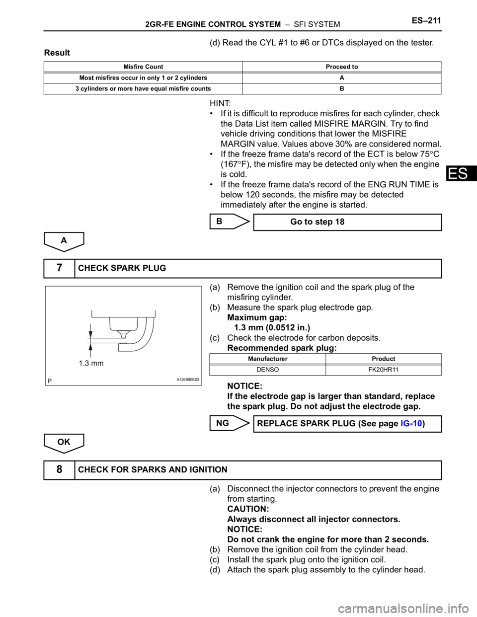
(d) Read the CYL #1 to #6 or DTCs displayed on the tester.
Result
HINT:
• If it is difficult to reproduce misfires for each cylinder, check
the Data List item called MISFIRE MARGIN. Try to find
vehicle driving conditions that lower the MISFIRE
MARGIN value. Values above 30% are considered normal.
• If the freeze frame data's record of the ECT is below 75
C
(167
F), the misfire may be detected only when the engine
is cold.
• If the freeze frame data's record of the ENG RUN TIME is
below 120 seconds, the misfire may be detected
immediately after the engine is started.
B
A
(a) Remove the ignition coil and the spark plug of the
misfiring cylinder.
(b) Measure the spark plug electrode gap.
Maximum gap:
1.3 mm (0.0512 in.)
(c) Check the electrode for carbon deposits.
Recommended spark plug:
NOTICE:
If the electrode gap is larger than standard, replace
the spark plug. Do not adjust the electrode gap.
NG
OK
(a) Disconnect the injector connectors to prevent the engine
from starting.
CAUTION:
Always disconnect all injector connectors.
NOTICE:
Do not crank the engine for more than 2 seconds.
(b) Remove the ignition coil from the cylinder head.
(c) Install the spark plug onto the ignition coil.
(d) Attach the spark plug assembly to the cylinder head.
Misfire Count Proceed to
Most misfires occur in only 1 or 2 cylinders A
3 cylinders or more have equal misfire counts B
Go to step 18
7CHECK SPARK PLUG
A126880E03
Manufacturer Product
DENSO FK20HR11
REPLACE SPARK PLUG (See page IG-10)
8CHECK FOR SPARKS AND IGNITION
Page 519 of 3000
2GR-FE ENGINE CONTROL SYSTEM – SFI SYSTEMES–213
ES
Cylinder No. 5
Cylinder No. 6
NG
OK
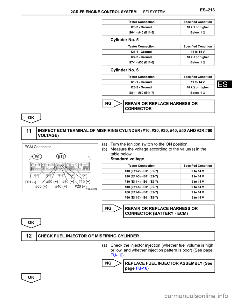
(a) Turn the ignition switch to the ON position.
(b) Measure the voltage according to the value(s) in the
table below.
Standard voltage
NG
OK
(a) Check the injector injection (whether fuel volume is high
or low, and whether injection pattern is poor) (See page
FU-16).
NG
OK
I26-2 - Ground 10 k or higher
I26-1 - #40 (E11-5) Below 1
Tester Connection Specified Condition
I27-1 - Ground 11 to 14 V
I27-2 - Ground 10 k
or higher
I27-1 - #50 (E11-6) Below 1
Tester Connection Specified Condition
I28-1 - Ground 11 to 14 V
I28-2 - Ground 10 k
or higher
I28-1 - #60 (E11-7) Below 1
REPAIR OR REPLACE HARNESS OR
CONNECTOR
Tester Connection Specified Condition
11INSPECT ECM TERMINAL OF MISFIRING CYLINDER (#10, #20, #30, #40, #50 AND /OR #60
VOLTAGE)
A162489E04
Tester Connection Specified Condition
#10 (E11-2) - E01 (E9-7) 9 to 14 V
#20 (E11-3) - E01 (E9-7) 9 to 14 V
#30 (E11-4) - E01 (E9-7) 9 to 14 V
#40 (E11-5) - E01 (E9-7) 9 to 14 V
#50 (E11-6) - E01 (E9-7) 9 to 14 V
#60 (E11-7) - E01 (E9-7) 9 to 14 V
REPAIR OR REPLACE HARNESS OR
CONNECTOR (BATTERY - ECM)
12CHECK FUEL INJECTOR OF MISFIRING CYLINDER
REPLACE FUEL INJECTOR ASSEMBLY (See
page FU-16)
Page 523 of 3000
2GR-FE ENGINE CONTROL SYSTEM – SFI SYSTEMES–217
ES
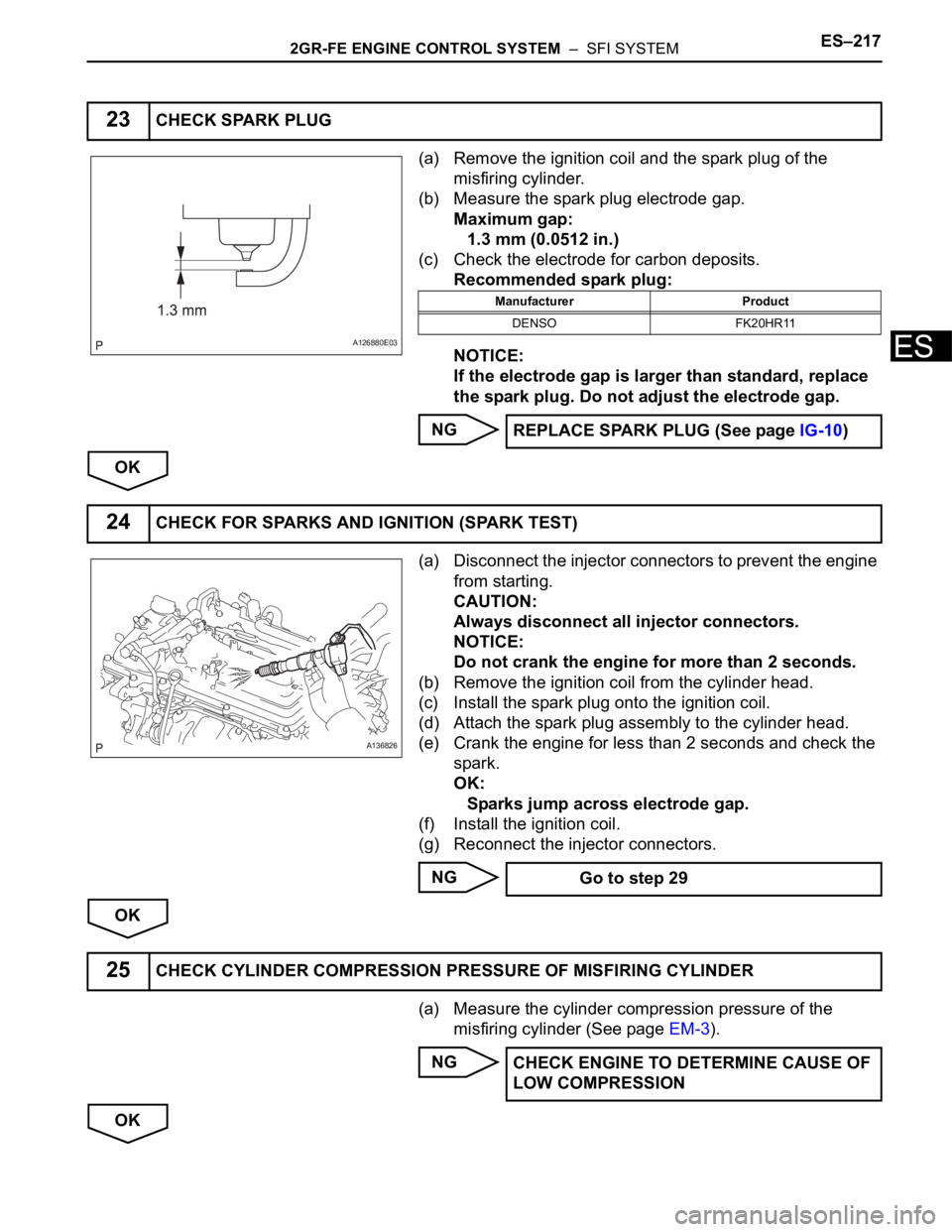
(a) Remove the ignition coil and the spark plug of the
misfiring cylinder.
(b) Measure the spark plug electrode gap.
Maximum gap:
1.3 mm (0.0512 in.)
(c) Check the electrode for carbon deposits.
Recommended spark plug:
NOTICE:
If the electrode gap is larger than standard, replace
the spark plug. Do not adjust the electrode gap.
NG
OK
(a) Disconnect the injector connectors to prevent the engine
from starting.
CAUTION:
Always disconnect all injector connectors.
NOTICE:
Do not crank the engine for more than 2 seconds.
(b) Remove the ignition coil from the cylinder head.
(c) Install the spark plug onto the ignition coil.
(d) Attach the spark plug assembly to the cylinder head.
(e) Crank the engine for less than 2 seconds and check the
spark.
OK:
Sparks jump across electrode gap.
(f) Install the ignition coil.
(g) Reconnect the injector connectors.
NG
OK
(a) Measure the cylinder compression pressure of the
misfiring cylinder (See page EM-3).
NG
OK
23CHECK SPARK PLUG
A126880E03
Manufacturer Product
DENSO FK20HR11
REPLACE SPARK PLUG (See page IG-10)
24CHECK FOR SPARKS AND IGNITION (SPARK TEST)
A136826
Go to step 29
25CHECK CYLINDER COMPRESSION PRESSURE OF MISFIRING CYLINDER
CHECK ENGINE TO DETERMINE CAUSE OF
LOW COMPRESSION
Page 525 of 3000
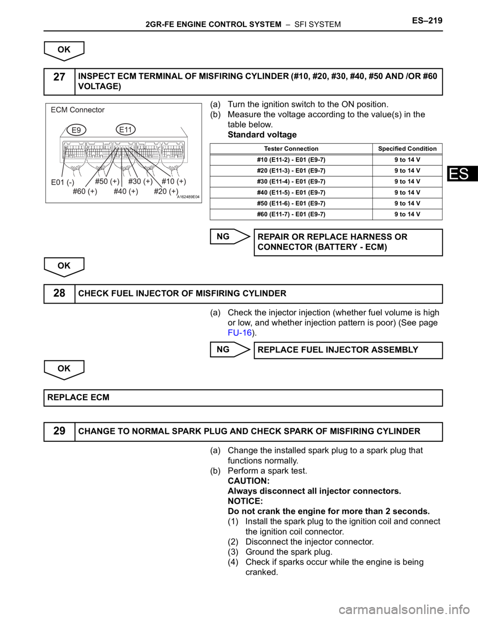
2GR-FE ENGINE CONTROL SYSTEM – SFI SYSTEMES–219
ES
OK
(a) Turn the ignition switch to the ON position.
(b) Measure the voltage according to the value(s) in the
table below.
Standard voltage
NG
OK
(a) Check the injector injection (whether fuel volume is high
or low, and whether injection pattern is poor) (See page
FU-16).
NG
OK
(a) Change the installed spark plug to a spark plug that
functions normally.
(b) Perform a spark test.
CAUTION:
Always disconnect all injector connectors.
NOTICE:
Do not crank the engine for more than 2 seconds.
(1) Install the spark plug to the ignition coil and connect
the ignition coil connector.
(2) Disconnect the injector connector.
(3) Ground the spark plug.
(4) Check if sparks occur while the engine is being
cranked.
27INSPECT ECM TERMINAL OF MISFIRING CYLINDER (#10, #20, #30, #40, #50 AND /OR #60
VOLTAGE)
A162489E04
Tester Connection Specified Condition
#10 (E11-2) - E01 (E9-7) 9 to 14 V
#20 (E11-3) - E01 (E9-7) 9 to 14 V
#30 (E11-4) - E01 (E9-7) 9 to 14 V
#40 (E11-5) - E01 (E9-7) 9 to 14 V
#50 (E11-6) - E01 (E9-7) 9 to 14 V
#60 (E11-7) - E01 (E9-7) 9 to 14 V
REPAIR OR REPLACE HARNESS OR
CONNECTOR (BATTERY - ECM)
28CHECK FUEL INJECTOR OF MISFIRING CYLINDER
REPLACE FUEL INJECTOR ASSEMBLY
REPLACE ECM
29CHANGE TO NORMAL SPARK PLUG AND CHECK SPARK OF MISFIRING CYLINDER
Page 544 of 3000
ES–2382GR-FE ENGINE CONTROL SYSTEM – SFI SYSTEM
ES
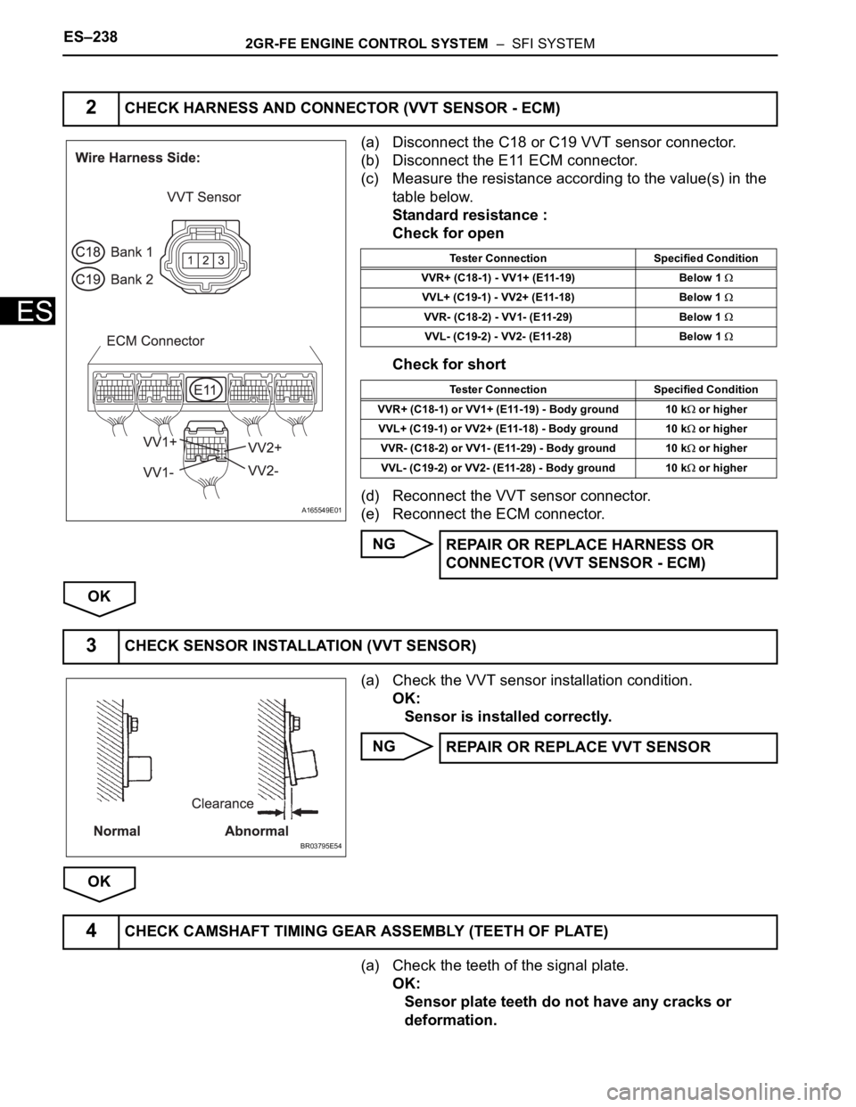
(a) Disconnect the C18 or C19 VVT sensor connector.
(b) Disconnect the E11 ECM connector.
(c) Measure the resistance according to the value(s) in the
table below.
Standard resistance :
Check for open
Check for short
(d) Reconnect the VVT sensor connector.
(e) Reconnect the ECM connector.
NG
OK
(a) Check the VVT sensor installation condition.
OK:
Sensor is installed correctly.
NG
OK
(a) Check the teeth of the signal plate.
OK:
Sensor plate teeth do not have any cracks or
deformation.
2CHECK HARNESS AND CONNECTOR (VVT SENSOR - ECM)
A165549E01
Tester Connection Specified Condition
VVR+ (C18-1) - VV1+ (E11-19) Below 1
VVL+ (C19-1) - VV2+ (E11-18) Below 1
VVR- (C18-2) - VV1- (E11-29) Below 1
VVL- (C19-2) - VV2- (E11-28) Below 1
Tester Connection Specified Condition
VVR+ (C18-1) or VV1+ (E11-19) - Body ground 10 k
or higher
VVL+ (C19-1) or VV2+ (E11-18) - Body ground 10 k
or higher
VVR- (C18-2) or VV1- (E11-29) - Body ground 10 k
or higher
VVL- (C19-2) or VV2- (E11-28) - Body ground 10 k
or higher
REPAIR OR REPLACE HARNESS OR
CONNECTOR (VVT SENSOR - ECM)
3CHECK SENSOR INSTALLATION (VVT SENSOR)
BR03795E54
REPAIR OR REPLACE VVT SENSOR
4CHECK CAMSHAFT TIMING GEAR ASSEMBLY (TEETH OF PLATE)
Page 545 of 3000
2GR-FE ENGINE CONTROL SYSTEM – SFI SYSTEMES–239
ES
NG
OK
(a) Replace the VVT sensor (See page ES-509).
NEXT
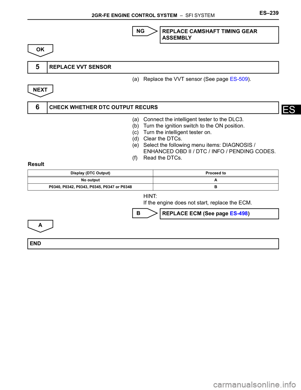
(a) Connect the intelligent tester to the DLC3.
(b) Turn the ignition switch to the ON position.
(c) Turn the intelligent tester on.
(d) Clear the DTCs.
(e) Select the following menu items: DIAGNOSIS /
ENHANCED OBD II / DTC / INFO / PENDING CODES.
(f) Read the DTCs.
Result
HINT:
If the engine does not start, replace the ECM.
B
AREPLACE CAMSHAFT TIMING GEAR
ASSEMBLY
5REPLACE VVT SENSOR
6CHECK WHETHER DTC OUTPUT RECURS
Display (DTC Output) Proceed to
No output A
P0340, P0342, P0343, P0345, P0347 or P0348 B
REPLACE ECM (See page ES-498)
END
Page 554 of 3000
ES–2482GR-FE ENGINE CONTROL SYSTEM – SFI SYSTEM
ES
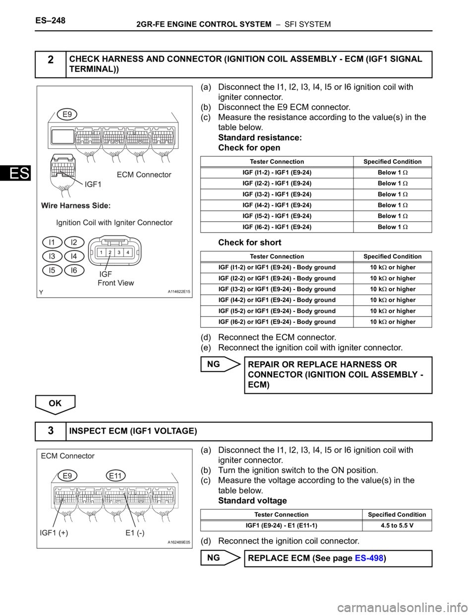
(a) Disconnect the I1, I2, I3, I4, I5 or I6 ignition coil with
igniter connector.
(b) Disconnect the E9 ECM connector.
(c) Measure the resistance according to the value(s) in the
table below.
Standard resistance:
Check for open
Check for short
(d) Reconnect the ECM connector.
(e) Reconnect the ignition coil with igniter connector.
NG
OK
(a) Disconnect the I1, I2, I3, I4, I5 or I6 ignition coil with
igniter connector.
(b) Turn the ignition switch to the ON position.
(c) Measure the voltage according to the value(s) in the
table below.
Standard voltage
(d) Reconnect the ignition coil connector.
NG
2CHECK HARNESS AND CONNECTOR (IGNITION COIL ASSEMBLY - ECM (IGF1 SIGNAL
TERMINAL))
A114622E15
Tester Connection Specified Condition
IGF (I1-2) - IGF1 (E9-24) Below 1
IGF (I2-2) - IGF1 (E9-24) Below 1
IGF (I3-2) - IGF1 (E9-24) Below 1
IGF (I4-2) - IGF1 (E9-24) Below 1
IGF (I5-2) - IGF1 (E9-24) Below 1
IGF (I6-2) - IGF1 (E9-24) Below 1
Tester Connection Specified Condition
IGF (I1-2) or IGF1 (E9-24) - Body ground 10 k
or higher
IGF (I2-2) or IGF1 (E9-24) - Body ground 10 k
or higher
IGF (I3-2) or IGF1 (E9-24) - Body ground 10 k
or higher
IGF (I4-2) or IGF1 (E9-24) - Body ground 10 k
or higher
IGF (I5-2) or IGF1 (E9-24) - Body ground 10 k
or higher
IGF (I6-2) or IGF1 (E9-24) - Body ground 10 k
or higher
REPAIR OR REPLACE HARNESS OR
CONNECTOR (IGNITION COIL ASSEMBLY -
ECM)
3INSPECT ECM (IGF1 VOLTAGE)
A162489E05
Tester Connection Specified Condition
IGF1 (E9-24) - E1 (E11-1) 4.5 to 5.5 V
REPLACE ECM (See page ES-498)