2007 TOYOTA SIENNA engine assembly
[x] Cancel search: engine assemblyPage 383 of 3000
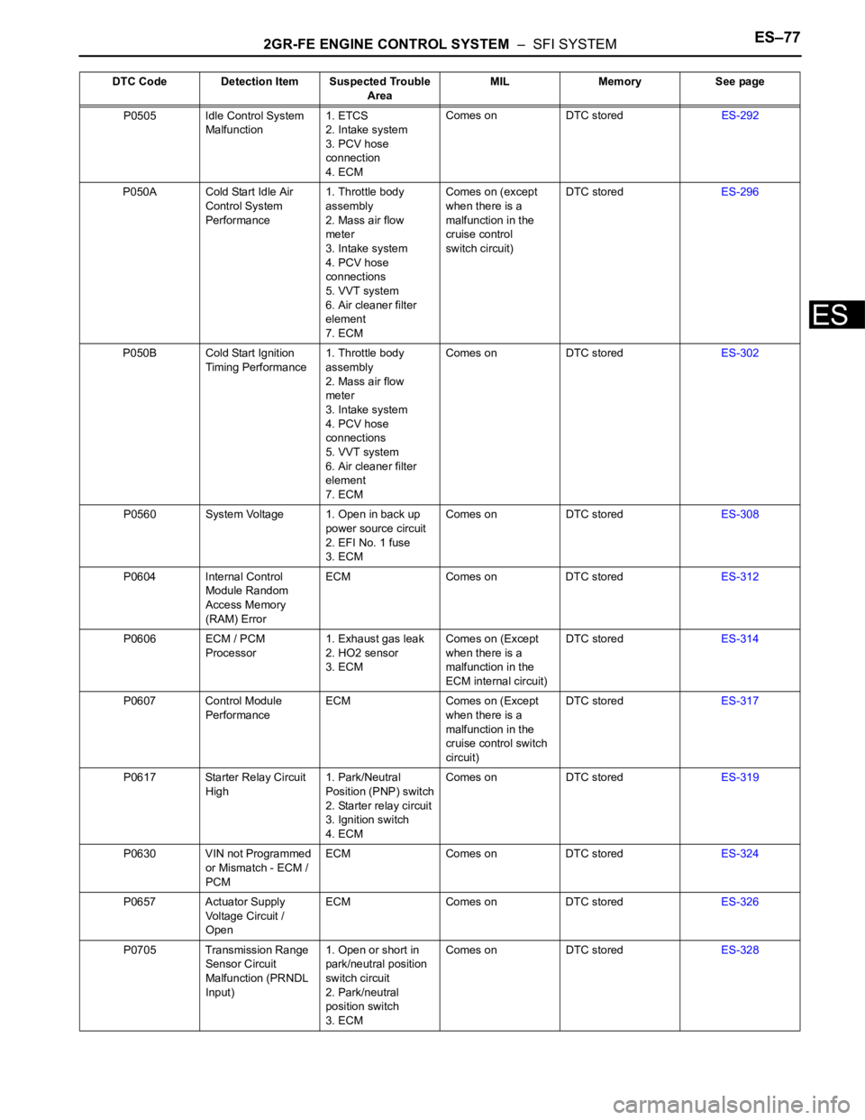
2GR-FE ENGINE CONTROL SYSTEM – SFI SYSTEMES–77
ES
P0505 Idle Control System
Malfunction1. ETCS
2. Intake system
3. PCV hose
connection
4. ECMComes on DTC storedES-292
P050A Cold Start Idle Air
Control System
Performance1. Throttle body
assembly
2. Mass air flow
meter
3. Intake system
4. PCV hose
connections
5. VVT system
6. Air cleaner filter
element
7. ECMComes on (except
when there is a
malfunction in the
cruise control
switch circuit)DTC storedES-296
P050B Cold Start Ignition
Timing Performance1. Throttle body
assembly
2. Mass air flow
meter
3. Intake system
4. PCV hose
connections
5. VVT system
6. Air cleaner filter
element
7. ECMComes on DTC storedES-302
P0560 System Voltage 1. Open in back up
power source circuit
2. EFI No. 1 fuse
3. ECMComes on DTC storedES-308
P0604 Internal Control
Module Random
Access Memory
(RAM) ErrorECM Comes on DTC storedES-312
P0606 ECM / PCM
Processor1. Exhaust gas leak
2. HO2 sensor
3. ECMComes on (Except
when there is a
malfunction in the
ECM internal circuit)DTC storedES-314
P0607 Control Module
PerformanceECM Comes on (Except
when there is a
malfunction in the
cruise control switch
circuit)DTC storedES-317
P0617 Starter Relay Circuit
High1. Park/Neutral
Position (PNP) switch
2. Starter relay circuit
3. Ignition switch
4. ECMComes on DTC storedES-319
P0630 VIN not Programmed
or Mismatch - ECM /
PCMECM Comes on DTC storedES-324
P0657 Actuator Supply
Voltage Circuit /
OpenECM Comes on DTC storedES-326
P0705 Transmission Range
Sensor Circuit
Malfunction (PRNDL
Input)1. Open or short in
park/neutral position
switch circuit
2. Park/neutral
position switch
3. ECMComes on DTC storedES-328 DTC Code Detection Item Suspected Trouble
AreaMIL Memory See page
Page 391 of 3000
2GR-FE ENGINE CONTROL SYSTEM – SFI SYSTEMES–85
ES
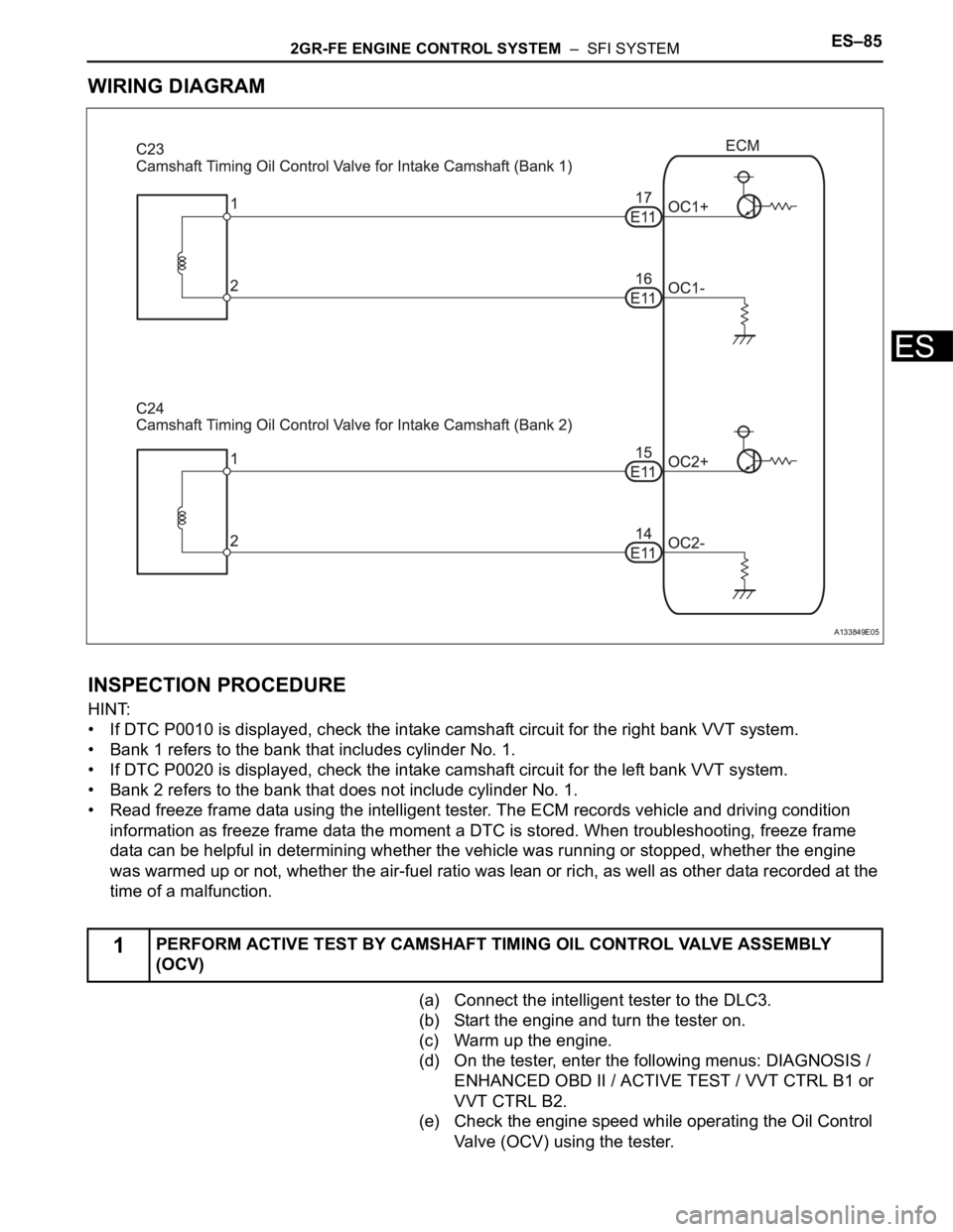
WIRING DIAGRAM
INSPECTION PROCEDURE
HINT:
• If DTC P0010 is displayed, check the intake camshaft circuit for the right bank VVT system.
• Bank 1 refers to the bank that includes cylinder No. 1.
• If DTC P0020 is displayed, check the intake camshaft circuit for the left bank VVT system.
• Bank 2 refers to the bank that does not include cylinder No. 1.
• Read freeze frame data using the intelligent tester. The ECM records vehicle and driving condition
information as freeze frame data the moment a DTC is stored. When troubleshooting, freeze frame
data can be helpful in determining whether the vehicle was running or stopped, whether the engine
was warmed up or not, whether the air-fuel ratio was lean or rich, as well as other data recorded at the
time of a malfunction.
(a) Connect the intelligent tester to the DLC3.
(b) Start the engine and turn the tester on.
(c) Warm up the engine.
(d) On the tester, enter the following menus: DIAGNOSIS /
ENHANCED OBD II / ACTIVE TEST / VVT CTRL B1 or
VVT CTRL B2.
(e) Check the engine speed while operating the Oil Control
Valve (OCV) using the tester.
1PERFORM ACTIVE TEST BY CAMSHAFT TIMING OIL CONTROL VALVE ASSEMBLY
(OCV)
A133849E05
Page 392 of 3000
ES–862GR-FE ENGINE CONTROL SYSTEM – SFI SYSTEM
ES
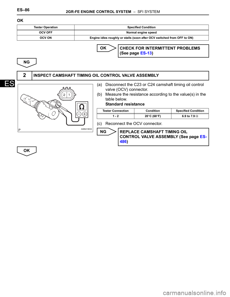
OK
OK
NG
(a) Disconnect the C23 or C24 camshaft timing oil control
valve (OCV) connector.
(b) Measure the resistance according to the value(s) in the
table below.
Standard resistance
(c) Reconnect the OCV connector.
NG
OK
Tester Operation Specified Condition
OCV OFF Normal engine speed
OCV ON Engine idles roughly or stalls (soon after OCV switched from OFF to ON)
CHECK FOR INTERMITTENT PROBLEMS
(See page ES-13)
2INSPECT CAMSHAFT TIMING OIL CONTROL VALVE ASSEMBLY
A095415E03
Tester Connection Condition Specified Condition
1 - 2 20
C (68F) 6.9 to 7.9
REPLACE CAMSHAFT TIMING OIL
CONTROL VALVE ASSEMBLY (See page ES-
486)
Page 394 of 3000
ES–882GR-FE ENGINE CONTROL SYSTEM – SFI SYSTEM
ES
HINT:
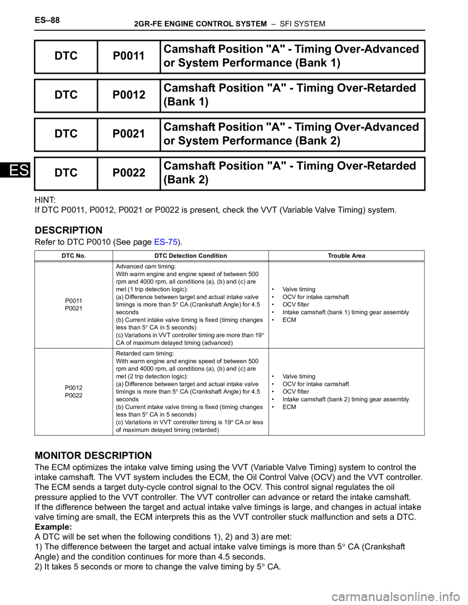
If DTC P0011, P0012, P0021 or P0022 is present, check the VVT (Variable Valve Timing) system.
DESCRIPTION
Refer to DTC P0010 (See page ES-75).
MONITOR DESCRIPTION
The ECM optimizes the intake valve timing using the VVT (Variable Valve Timing) system to control the
intake camshaft. The VVT system includes the ECM, the Oil Control Valve (OCV) and the VVT controller.
The ECM sends a target duty-cycle control signal to the OCV. This control signal regulates the oil
pressure applied to the VVT controller. The VVT controller can advance or retard the intake camshaft.
If the difference between the target and actual intake valve timings is large, and changes in actual intake
valve timing are small, the ECM interprets this as the VVT controller stuck malfunction and sets a DTC.
Example:
A DTC will be set when the following conditions 1), 2) and 3) are met:
1) The difference between the target and actual intake valve timings is more than 5
CA (Crankshaft
Angle) and the condition continues for more than 4.5 seconds.
2) It takes 5 seconds or more to change the valve timing by 5
CA.
DTC P0011Camshaft Position "A" - Timing Over-Advanced
or System Performance (Bank 1)
DTC P0012Camshaft Position "A" - Timing Over-Retarded
(Bank 1)
DTC P0021Camshaft Position "A" - Timing Over-Advanced
or System Performance (Bank 2)
DTC P0022Camshaft Position "A" - Timing Over-Retarded
(Bank 2)
DTC No. DTC Detection Condition Trouble Area
P0011
P0021Advanced cam timing:
With warm engine and engine speed of between 500
rpm and 4000 rpm, all conditions (a), (b) and (c) are
met (1 trip detection logic):
(a) Difference between target and actual intake valve
timings is more than 5
CA (Crankshaft Angle) for 4.5
seconds
(b) Current intake valve timing is fixed (timing changes
less than 5
CA in 5 seconds)
(c) Variations in VVT controller timing are more than 19
CA of maximum delayed timing (advanced)• Valve timing
• OCV for intake camshaft
• OCV filter
• Intake camshaft (bank 1) timing gear assembly
•ECM
P0012
P0022Retarded cam timing:
With warm engine and engine speed of between 500
rpm and 4000 rpm, all conditions (a), (b) and (c) are
met (2 trip detection logic):
(a) Difference between target and actual intake valve
timings is more than 5
CA (Crankshaft Angle) for 4.5
seconds
(b) Current intake valve timing is fixed (timing changes
less than 5
CA in 5 seconds)
(c) Variations in VVT controller timing is 19
CA or less
of maximum delayed timing (retarded)• Valve timing
• OCV for intake camshaft
• OCV filter
• Intake camshaft (bank 2) timing gear assembly
•ECM
Page 398 of 3000
ES–922GR-FE ENGINE CONTROL SYSTEM – SFI SYSTEM
ES
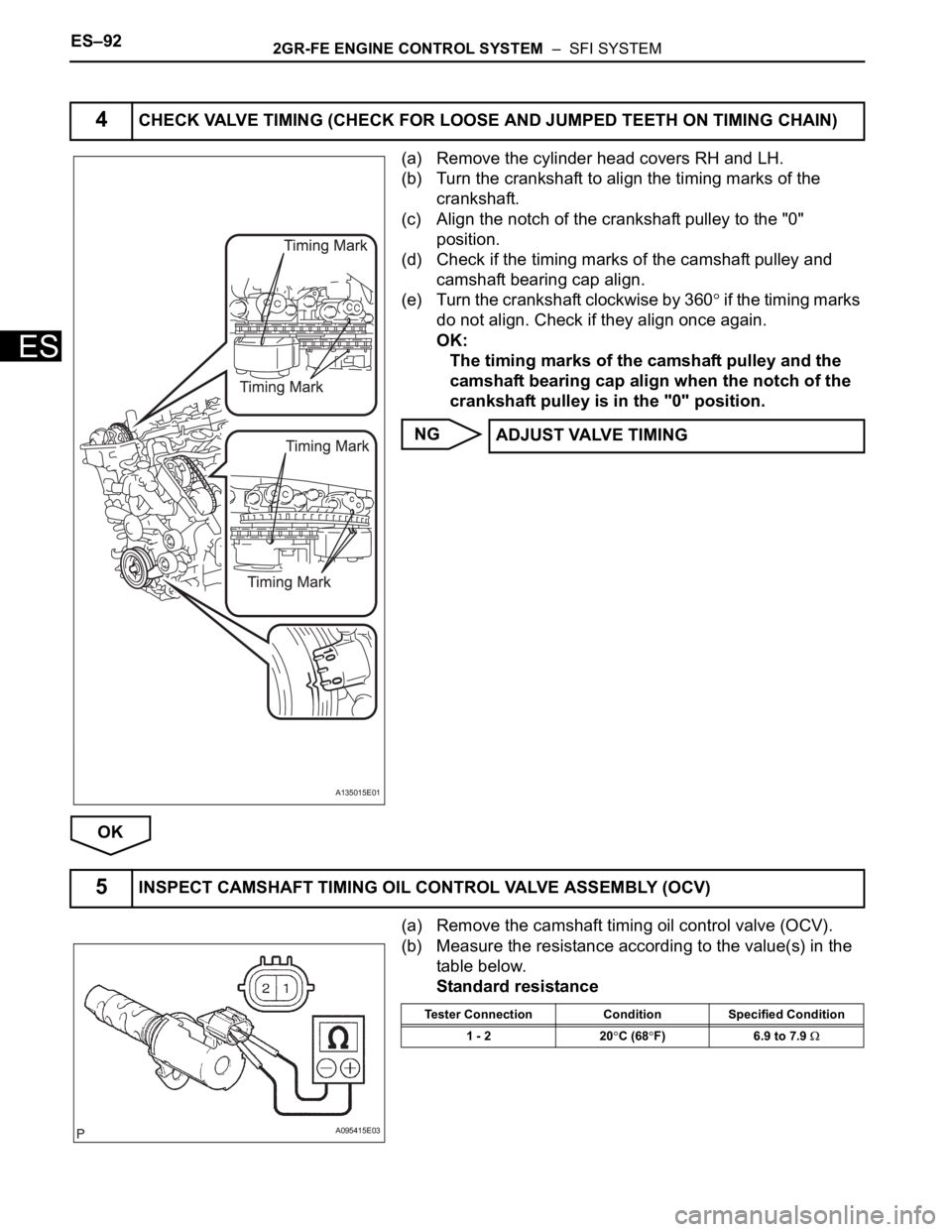
(a) Remove the cylinder head covers RH and LH.
(b) Turn the crankshaft to align the timing marks of the
crankshaft.
(c) Align the notch of the crankshaft pulley to the "0"
position.
(d) Check if the timing marks of the camshaft pulley and
camshaft bearing cap align.
(e) Turn the crankshaft clockwise by 360
if the timing marks
do not align. Check if they align once again.
OK:
The timing marks of the camshaft pulley and the
camshaft bearing cap align when the notch of the
crankshaft pulley is in the "0" position.
NG
OK
(a) Remove the camshaft timing oil control valve (OCV).
(b) Measure the resistance according to the value(s) in the
table below.
Standard resistance
4CHECK VALVE TIMING (CHECK FOR LOOSE AND JUMPED TEETH ON TIMING CHAIN)
A135015E01
ADJUST VALVE TIMING
5INSPECT CAMSHAFT TIMING OIL CONTROL VALVE ASSEMBLY (OCV)
A095415E03
Tester Connection Condition Specified Condition
1 - 2 20
C (68F) 6.9 to 7.9
Page 399 of 3000
2GR-FE ENGINE CONTROL SYSTEM – SFI SYSTEMES–93
ES
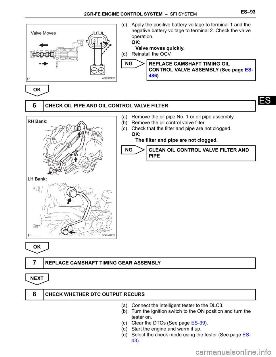
(c) Apply the positive battery voltage to terminal 1 and the
negative battery voltage to terminal 2. Check the valve
operation.
OK:
Valve moves quickly.
(d) Reinstall the OCV.
NG
OK
(a) Remove the oil pipe No. 1 or oil pipe assembly.
(b) Remove the oil control valve filter.
(c) Check that the filter and pipe are not clogged.
OK:
The filter and pipe are not clogged.
NG
OK
NEXT
(a) Connect the intelligent tester to the DLC3.
(b) Turn the ignition switch to the ON position and turn the
tester on.
(c) Clear the DTCs (See page ES-39).
(d) Start the engine and warm it up.
(e) Select the check mode using the tester (See page ES-
43).
A097066E08
REPLACE CAMSHAFT TIMING OIL
CONTROL VALVE ASSEMBLY (See page ES-
486)
6CHECK OIL PIPE AND OIL CONTROL VALVE FILTER
G042497E01
CLEAN OIL CONTROL VALVE FILTER AND
PIPE
7REPLACE CAMSHAFT TIMING GEAR ASSEMBLY
8CHECK WHETHER DTC OUTPUT RECURS
Page 404 of 3000
ES–982GR-FE ENGINE CONTROL SYSTEM – SFI SYSTEM
ES
OK
NG
OK
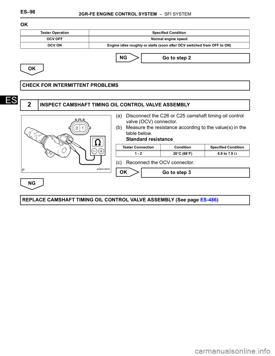
(a) Disconnect the C26 or C25 camshaft timing oil control
valve (OCV) connector.
(b) Measure the resistance according to the value(s) in the
table below.
Standard resistance
(c) Reconnect the OCV connector.
OK
NG
Tester Operation Specified Condition
OCV OFF Normal engine speed
OCV ON Engine idles roughly or stalls (soon after OCV switched from OFF to ON)
Go to step 2
CHECK FOR INTERMITTENT PROBLEMS
2INSPECT CAMSHAFT TIMING OIL CONTROL VALVE ASSEMBLY
A095415E03
Tester Connection Condition Specified Condition
1 - 2 20
C (68F) 6.9 to 7.9
Go to step 3
REPLACE CAMSHAFT TIMING OIL CONTROL VALVE ASSEMBLY (See page ES-486)
Page 406 of 3000
ES–1002GR-FE ENGINE CONTROL SYSTEM – SFI SYSTEM
ES
HINT:
If DTC P0014, P0015, P0024 or P0025 is present, check the VVT (Variable Valve Timing) system.
DESCRIPTION
Refer to DTC P0013 (See page ES-87).
MONITOR DESCRIPTION
DTC P0014 and P0024
The ECM compares current valve timing with target valve timing, while the engine is running and after
being warmed up, in order to monitor the VVT system on the exhaust side. Valve timing is calculated from
the positions of the camshaft and crankshaft. The ECM controls the engine so that current valve timing
meets target valve timing. If these timings are not met, the ECM determines this as a malfunction.
DTC P0015 and P0025
The ECM compares current valve timing with target valve timing, while the engine is running and after
being warmed up, in order to monitor the VVT system on the exhaust side. Valve timing is calculated from
the positions of the camshaft and crankshaft. The ECM controls the engine so that current valve timing
meets target valve timing. If these timings are not met, the ECM determines this as a malfunction.
DTC P0014Camshaft Position "B" - Timing Over-Advanced
or System Performance (Bank 1)
DTC P0015Camshaft Position "B" - Timing Over-Retarded
(Bank 1)
DTC P0024Camshaft Position "B" - Timing Over-Advanced
or System Performance (Bank 2)
DTC P0025Camshaft Position "B" - Timing Over-Retarded
(Bank 2)
DTC No. DTC Detection Condition Trouble Area
P0014
P0024Advanced cam timing:
With warm engine and engine speed of between 500
rpm and 4,000 rpm, all conditions (a), (b) and (c) are
met
(2 trip detection logic):
(a) Difference between target and actual exhaust valve
timing is more than 5
CA (Crankshaft Angle) for 4.5
seconds
(b) Current exhaust valve timing is fixed (timing
changes less than 5
CA in 5 seconds)
(c) Variations in VVT controller timing are more than
19
CA of maximum delayed timing (advanced)• Valve timing
• OCV for exhaust camshaft
• OCV filter
• Exhaust camshaft timing gear assembly
•ECM
P0015
P0025Retarded cam timing:
With warm engine and engine speed of between 500
rpm and 4,000 rpm, all conditions (a), (b) and (c) are
met
(1 trip detection logic):
(a) Difference between target and actual exhaust valve
timing is more than 5
CA (Crankshaft Angle) for 4.5
seconds
(b) Current exhaust valve timing is fixed (timing
changes less than 5
CA in 5 seconds)
(c) Variations in VVT controller timing are more than
19
CA or less of maximum delayed timing (retarded)• Valve timing
• OCV for exhaust camshaft
• OCV filter
• Exhaust camshaft timing gear assembly
•ECM