Page 69 of 3000

INTRODUCTION – HOW TO TROUBLESHOOT ECU CONTROLLED SYSTEMSIN–39
IN
• In the DTC check, it is very important to determine
whether the problem indicated by the DTC either: 1)
still occurs, or 2) occurred in the past but has returned
to normal. In addition, the DTC should be compared
to the problem symptom to see if they are related. For
this reason, DTCs should be checked before and after
confirmation of symptoms (i.e., whether or not
problem symptoms exist) to determine current system
conditions, as shown in the flowchart below.
• Never skip the DTC check. Failing to check DTCs
may, depending on the case, result in unnecessary
troubleshooting for systems operating normally or
lead to repairs not related to the problem. Follow the
procedures listed in the flowchart in the correct order.
Theft Deterrent System XXXXX
Engine Immobiliser System
XX
Cruise Control SystemXXX
Dynamic Laser Cruise Control System
XXX
Lighting System
XX
Wiper and Washer SystemXXXXX
Power Door Lock Control System X X X
Wireless Door Lock Control SystemXX
Key Reminder Warning System X X XX
Meter / Gauge System X X X
Audio and Visual SystemXXXX
Rear Seat Entertainment System XXXXX
Navigation System
XXXX
Clearance Sonar SystemXXXXX
Rear View Monitor System XXXXX
Power Window Control System (with Jam
Protection Function)XXX
Power Window Control System (without Jam
Protection Function)XXXXX
Power Mirror Control System (with Memory) X X X
Power Mirror Control System (without Memory)XXXXX
Front Power Seat Control System X X X
Rear No. 2 Seat Assembly (with Power Stowing
Function)XXXXX
Window Deogger SystemXXXXX
Power Slide Door System
XX
Slide Door Closer System X X X
Back Door Closer SystemXX
Power Back Door SystemXX
Sliding Roof System XXXXX
Multiplex Communication System XXXXX
CAN Communication System XXXXXSystemSYMPTOM CONFIRMATION AND DIAGNOSTIC TROUBLE CODE
DTC Check
(Normal Mode)DTC Check
(Check Mode)Sensor Check/
Test Mode
(Input Signal
Check)Data List Active Test
Page 78 of 3000
2GR-FE LUBRICATION – OIL PUMPLU–11
LU
REMOVAL
1. REMOVE ENGINE ASSEMBLY WITH TRANSAXLE
HINT:
See page EM-26
2. REMOVE OIL LEVEL GAUGE GUIDE SUB-
ASSEMBLY (See page EM-39)
3. REMOVE NO. 1 OIL PIPE (See page EM-77)
4. REMOVE OIL PIPE (See page EM-77)
5. REMOVE CRANKSHAFT PULLEY (See page EM-79)
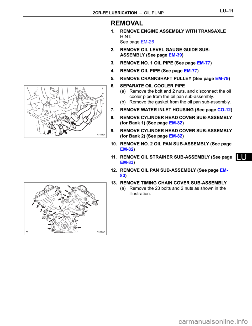
6. SEPARATE OIL COOLER PIPE
(a) Remove the bolt and 2 nuts, and disconnect the oil
cooler pipe from the oil pan sub-assembly.
(b) Remove the gasket from the oil pan sub-assembly.
7. REMOVE WATER INLET HOUSING (See page CO-12)
8. REMOVE CYLINDER HEAD COVER SUB-ASSEMBLY
(for Bank 1) (See page EM-82)
9. REMOVE CYLINDER HEAD COVER SUB-ASSEMBLY
(for Bank 2) (See page EM-82)
10. REMOVE NO. 2 OIL PAN SUB-ASSEMBLY (See page
EM-82)
11. REMOVE OIL STRAINER SUB-ASSEMBLY (See page
EM-83)
12. REMOVE OIL PAN SUB-ASSEMBLY (See page EM-
83)
13. REMOVE TIMING CHAIN COVER SUB-ASSEMBLY
(a) Remove the 23 bolts and 2 nuts as shown in the
illustration.
A141494
A128004
Page 80 of 3000

IG–62GR-FE IGNITION – IGNITION COIL AND SPARK PLUG
IG
ON-VEHICLE INSPECTION
NOTICE:
In this section, the terms "cold" and "hot" refer to the
temperature of the coils. "Cold" means approximately -
10
C (14F) to 50C (122F). "Hot" means approximately
50
C (122F) to 100C (212F).
1. INSPECT IGNITION COIL ASSEMBLY
(a) Check for DTCs.
NOTICE:
If any DTC is present, perform troubleshooting
in accordance with the procedures for that DTC.
(b) Remove the ignition coil assembly and spark plug.
(See page IG-8).
(c) Check that sparks occur.
(1) Disconnect the 6 fuel injector connectors.
(2) Install the spark plugs to each ignition coil, and
connect the ignition coil connectors.
(3) Ground the spark plugs.
(4) Check if a spark occurs at each spark plug
while the engine is being cranked.
NOTICE:
• Be sure to ground the spark plugs when
checking.
• Replace the ignition coil if it receives an
impact.
• Do not crank the engine for more than 2
seconds.
(d) Perform the spark test according to the flowchart
below.
(1) Check that the ignition coil connector is
securely connected.
Result
(2) Perform a spark test on each ignition coil.
1. Replace the ignition coil with a normal one.
2. Perform the spark test again.
Result
A133895
A133897
Result Proceed to
NG Connect securely
OK Go to next step
Result Proceed to
NG Go to next step
OK Replace ignition coil
Page 81 of 3000

2GR-FE IGNITION – IGNITION COIL AND SPARK PLUGIG–7
IG
(3) Check the spark plug (See page EM-1).
Result
(4) Check the power supply to the ignition coil.
1. Turn the ignition switch to the ON position.
2. Check that there is battery voltage at the
ignition coil positive (+) terminal.
Result
(5) Measure the resistance of the crankshaft
position sensor (See page ES-514).
Result
(6) Check the IGT signal from the ECM (See page
ES-233)
Result
(e) Using a 16 mm (0.63 in.) plug wrench, install the
spark plugs.
Torque: 18 N*m (184 kgf*cm, 13 ft.*lbf)
(f) Connect the 6 fuel injector connectors.
(g) Install the ignition coil assembly (See page IG-10).
2. INSPECT SPARK PLUG
NOTICE:
• Never use a wire brush for cleaning.
• Never attempt to adjust the electrode gap on a
used spark plug.
(a) Check the electrode.
(1) Using a megohmmeter, measure the insulation
resistance.
Standard insulation resistance:
10 M
or higher
HINT:
• If the result is 10 M
or less, clean the plug
and measure the resistance again.
• If a megohmmeter is not available, perform
the following simple inspection instead.
(b) Alternative inspection method:
(1) Quickly accelerate the engine to 4000 rpm 5
times.
Result Proceed to
NG Replace spark plug
OK Go to next step
Result Proceed to
NGCheck wiring between ignition
switch and ignition coil
OK Go to next step
Result Proceed to
NG Replace crankshaft position sensor
OK Go to next step
Result Proceed to
NG Check ECM
OKRepair wiring between ignition coil
and ECM
I039522E10
Page 82 of 3000

IG–82GR-FE IGNITION – IGNITION COIL AND SPARK PLUG
IG
(2) Remove the spark plugs.
(3) Visually check the spark plug.
If the electrode is dry, the spark plug is
functioning properly. If the electrode is damp,
proceed to the next step.
(c) Check the spark plug for any damage to its threads
and insulator. If there is damage, replace the spark
plug.
Recommended spark plug
NOTICE:
Use only the listed spark plug or equivalent to
ensure engine performance and smooth
driveability.
(d) Check the spark plug electrode gap.
Maximum electrode gap for used spark plug:
1.4 mm (0.055 in.)
If the gap is greater than the maximum, replace the
spark plug.
Electrode gap for new spark plug:
1.0 to 1.1 mm (0.039 to 0.043 in.)
(e) Clean the spark plugs.
If the electrode has traces of wet carbon, clean the
electrode with a spark plug cleaner and then dry it.
Standard air pressure:
588 kPa (6 kgf*cm
2, 85 psi)
Standard duration:
20 seconds or less
HINT:
Only use the spark plug cleaner when the electrode
is free of oil. If the electrode has traces of oil, use
gasoline to clean off the oil before using the spark
plug cleaner.
(f) Install the ignition coil assembly and spark plug.
(See page IG-10).
Manufacturer Spark Plug Type
DENSO FK20HR11
A163282E01
B062019
Page 87 of 3000
2GR-FE CHARGING – CHARGING SYSTEMCH–5
CH
PROBLEM SYMPTOMS TABLE
Result
Symptom Suspected Area See page
Charge Warning Light Comes ON while DrivingClutch pulley
CH-8
Generator assembly
Noise Occurs from Generator while Engine is RunningV-ribbed belt
CH-9 Clutch pulley
Generator assembly
Page 90 of 3000
U151E AUTOMATIC TRANSAXLE – AUTOMATIC TRANSAXLE ASSEMBLYAX–163
AX
REMOVAL
1. REMOVE ENGINE ASSEMBLY WITH TRANSAXLE
HINT:
(See page EM-26)
2. REMOVE FRONT DRIVE SHAFT ASSEMBLY LH
HINT:
(See page DS-6)
3. REMOVE FRONT DRIVE SHAFT ASSEMBLY RH
HINT:
(See page DS-6)
4. REMOVE TRANSMISSION CONTROL CABLE CLAMP
(a) Remove the bolt and the transmission control cable
clamp.
5. REMOVE WIRE HARNESS CLAMP
(a) Disconnect the wire harnesses from the clamp.
(b) Remove the 3 bolts and 2 clamps.
6. DISCONNECT WIRE HARNESS
(a) Remove the bolt and disconnect the wire harness.
C083203
D030465
G025456
Page 92 of 3000
U151E AUTOMATIC TRANSAXLE – AUTOMATIC TRANSAXLE ASSEMBLYAX–165
AX
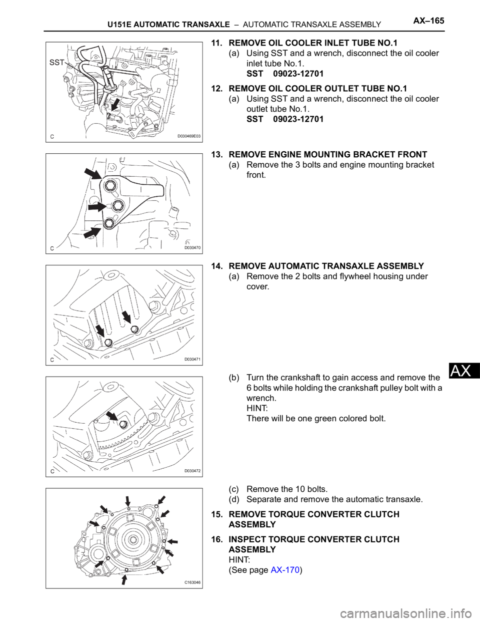
11. REMOVE OIL COOLER INLET TUBE NO.1
(a) Using SST and a wrench, disconnect the oil cooler
inlet tube No.1.
SST 09023-12701
12. REMOVE OIL COOLER OUTLET TUBE NO.1
(a) Using SST and a wrench, disconnect the oil cooler
outlet tube No.1.
SST 09023-12701
13. REMOVE ENGINE MOUNTING BRACKET FRONT
(a) Remove the 3 bolts and engine mounting bracket
front.
14. REMOVE AUTOMATIC TRANSAXLE ASSEMBLY
(a) Remove the 2 bolts and flywheel housing under
cover.
(b) Turn the crankshaft to gain access and remove the
6 bolts while holding the crankshaft pulley bolt with a
wrench.
HINT:
There will be one green colored bolt.
(c) Remove the 10 bolts.
(d) Separate and remove the automatic transaxle.
15. REMOVE TORQUE CONVERTER CLUTCH
ASSEMBLY
16. INSPECT TORQUE CONVERTER CLUTCH
ASSEMBLY
HINT:
(See page AX-170)
D030469E03
D030470
D030471
D030472
C163046