Page 726 of 3000
ES–4402GR-FE ENGINE CONTROL SYSTEM – SFI SYSTEM
ES
HINT:
When installing the fuel tank cap, tighten it until a few click
sounds are heard.
NEXT
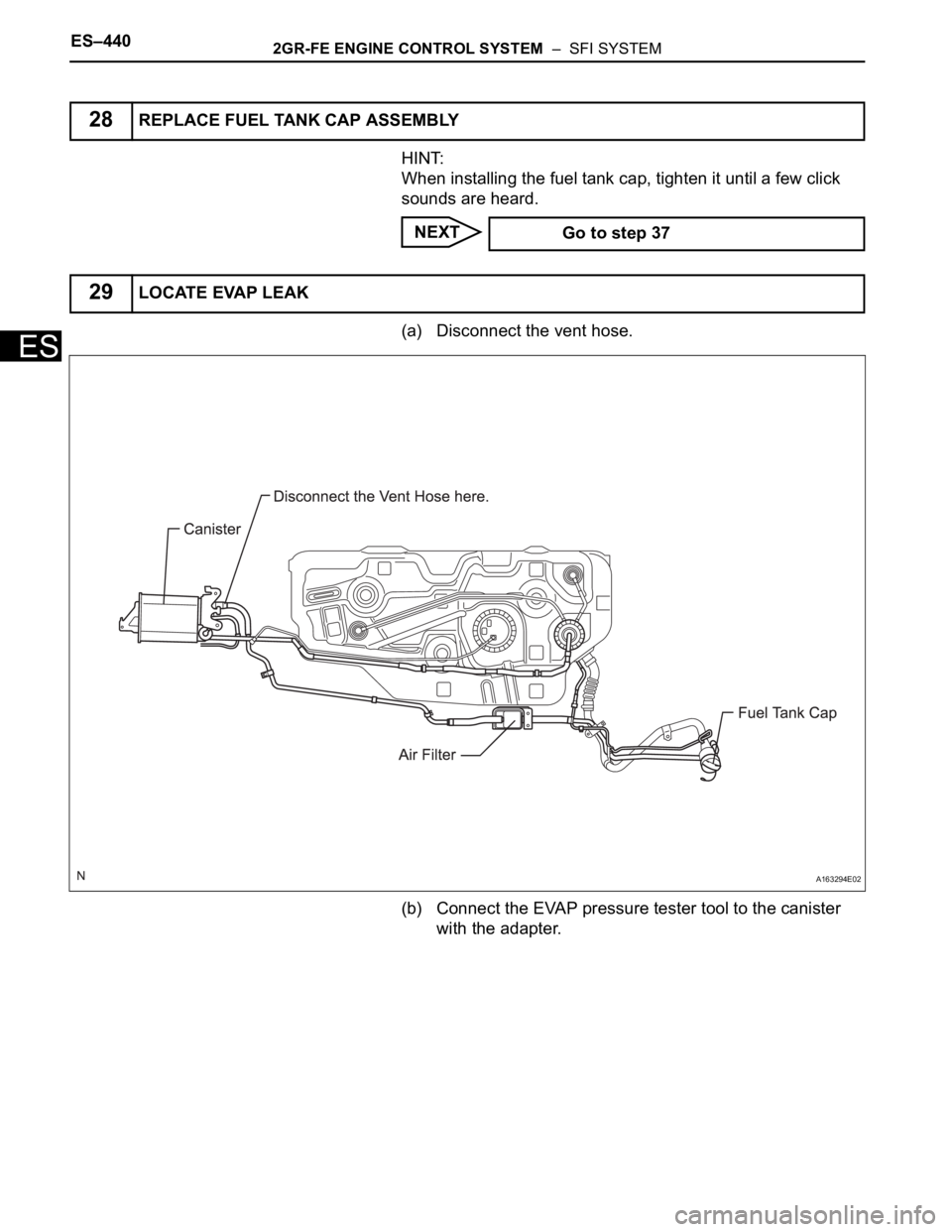
(a) Disconnect the vent hose.
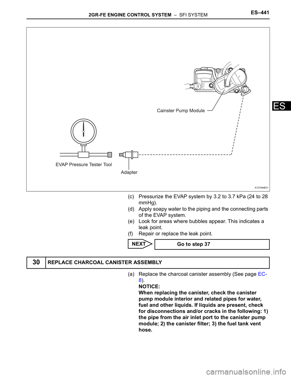
(b) Connect the EVAP pressure tester tool to the canister
with the adapter.
28REPLACE FUEL TANK CAP ASSEMBLY
Go to step 37
29LOCATE EVAP LEAK
A163294E02
Page 727 of 3000
2GR-FE ENGINE CONTROL SYSTEM – SFI SYSTEMES–441
ES
(c) Pressurize the EVAP system by 3.2 to 3.7 kPa (24 to 28
mmHg).
(d) Apply soapy water to the piping and the connecting parts
of the EVAP system.
(e) Look for areas where bubbles appear. This indicates a
leak point.
(f) Repair or replace the leak point.
NEXT
(a) Replace the charcoal canister assembly (See page EC-
8).
NOTICE:
When replacing the canister, check the canister
pump module interior and related pipes for water,
fuel and other liquids. If liquids are present, check
for disconnections and/or cracks in the following: 1)
the pipe from the air inlet port to the canister pump
module; 2) the canister filter; 3) the fuel tank vent
hose.
A137044E01
Go to step 37
30REPLACE CHARCOAL CANISTER ASSEMBLY
Page 733 of 3000
2GR-FE ENGINE CONTROL SYSTEM – SFI SYSTEMES–447
ES
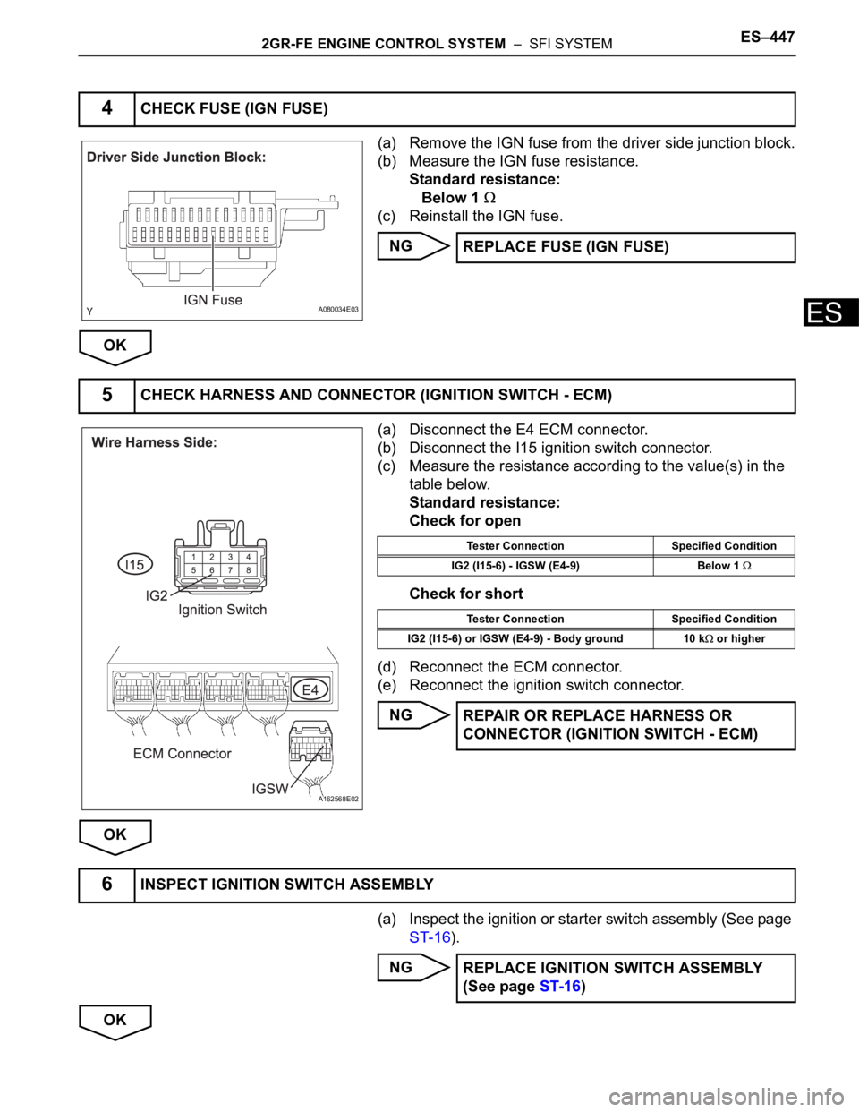
(a) Remove the IGN fuse from the driver side junction block.
(b) Measure the IGN fuse resistance.
Standard resistance:
Below 1
(c) Reinstall the IGN fuse.
NG
OK
(a) Disconnect the E4 ECM connector.
(b) Disconnect the I15 ignition switch connector.
(c) Measure the resistance according to the value(s) in the
table below.
Standard resistance:
Check for open
Check for short
(d) Reconnect the ECM connector.
(e) Reconnect the ignition switch connector.
NG
OK
(a) Inspect the ignition or starter switch assembly (See page
ST-16).
NG
OK
4CHECK FUSE (IGN FUSE)
A080034E03
REPLACE FUSE (IGN FUSE)
5CHECK HARNESS AND CONNECTOR (IGNITION SWITCH - ECM)
A162568E02
Tester Connection Specified Condition
IG2 (I15-6) - IGSW (E4-9) Below 1
Tester Connection Specified Condition
IG2 (I15-6) or IGSW (E4-9) - Body ground 10 k
or higher
REPAIR OR REPLACE HARNESS OR
CONNECTOR (IGNITION SWITCH - ECM)
6INSPECT IGNITION SWITCH ASSEMBLY
REPLACE IGNITION SWITCH ASSEMBLY
(See page ST-16)
Page 743 of 3000
2GR-FE ENGINE CONTROL SYSTEM – SFI SYSTEMES–457
ES
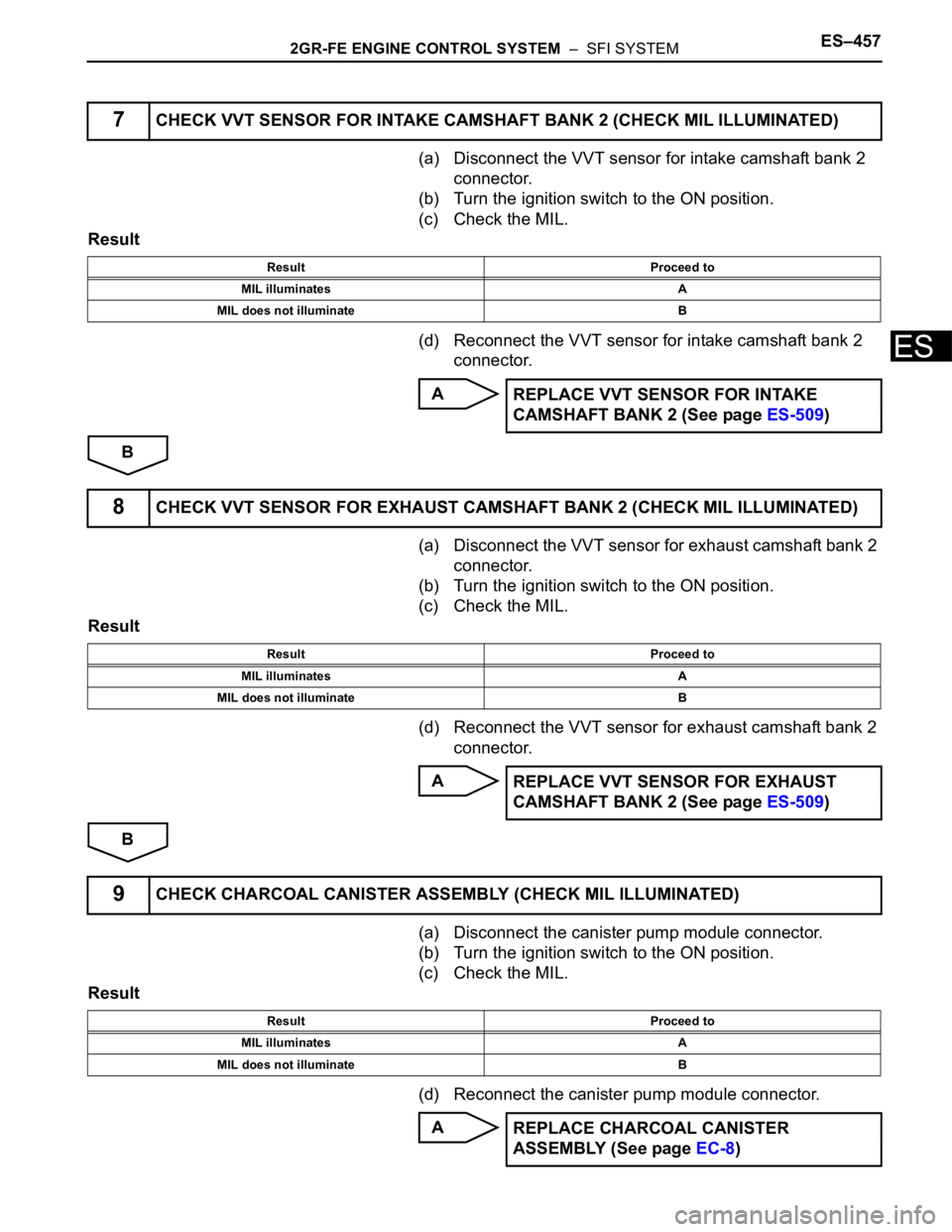
(a) Disconnect the VVT sensor for intake camshaft bank 2
connector.
(b) Turn the ignition switch to the ON position.
(c) Check the MIL.
Result
(d) Reconnect the VVT sensor for intake camshaft bank 2
connector.
A
B
(a) Disconnect the VVT sensor for exhaust camshaft bank 2
connector.
(b) Turn the ignition switch to the ON position.
(c) Check the MIL.
Result
(d) Reconnect the VVT sensor for exhaust camshaft bank 2
connector.
A
B
(a) Disconnect the canister pump module connector.
(b) Turn the ignition switch to the ON position.
(c) Check the MIL.
Result
(d) Reconnect the canister pump module connector.
A
7CHECK VVT SENSOR FOR INTAKE CAMSHAFT BANK 2 (CHECK MIL ILLUMINATED)
Result Proceed to
MIL illuminates A
MIL does not illuminate B
REPLACE VVT SENSOR FOR INTAKE
CAMSHAFT BANK 2 (See page ES-509)
8CHECK VVT SENSOR FOR EXHAUST CAMSHAFT BANK 2 (CHECK MIL ILLUMINAT E D )
Result Proceed to
MIL illuminates A
MIL does not illuminate B
REPLACE VVT SENSOR FOR EXHAUST
CAMSHAFT BANK 2 (See page ES-509)
9CHECK CHARCOAL CANISTER ASSEMBLY (CHECK MIL ILLUMINATED)
Result Proceed to
MIL illuminates A
MIL does not illuminate B
REPLACE CHARCOAL CANISTER
ASSEMBLY (See page EC-8)
Page 750 of 3000
ES–4642GR-FE ENGINE CONTROL SYSTEM – SFI SYSTEM
ES
NG
OK
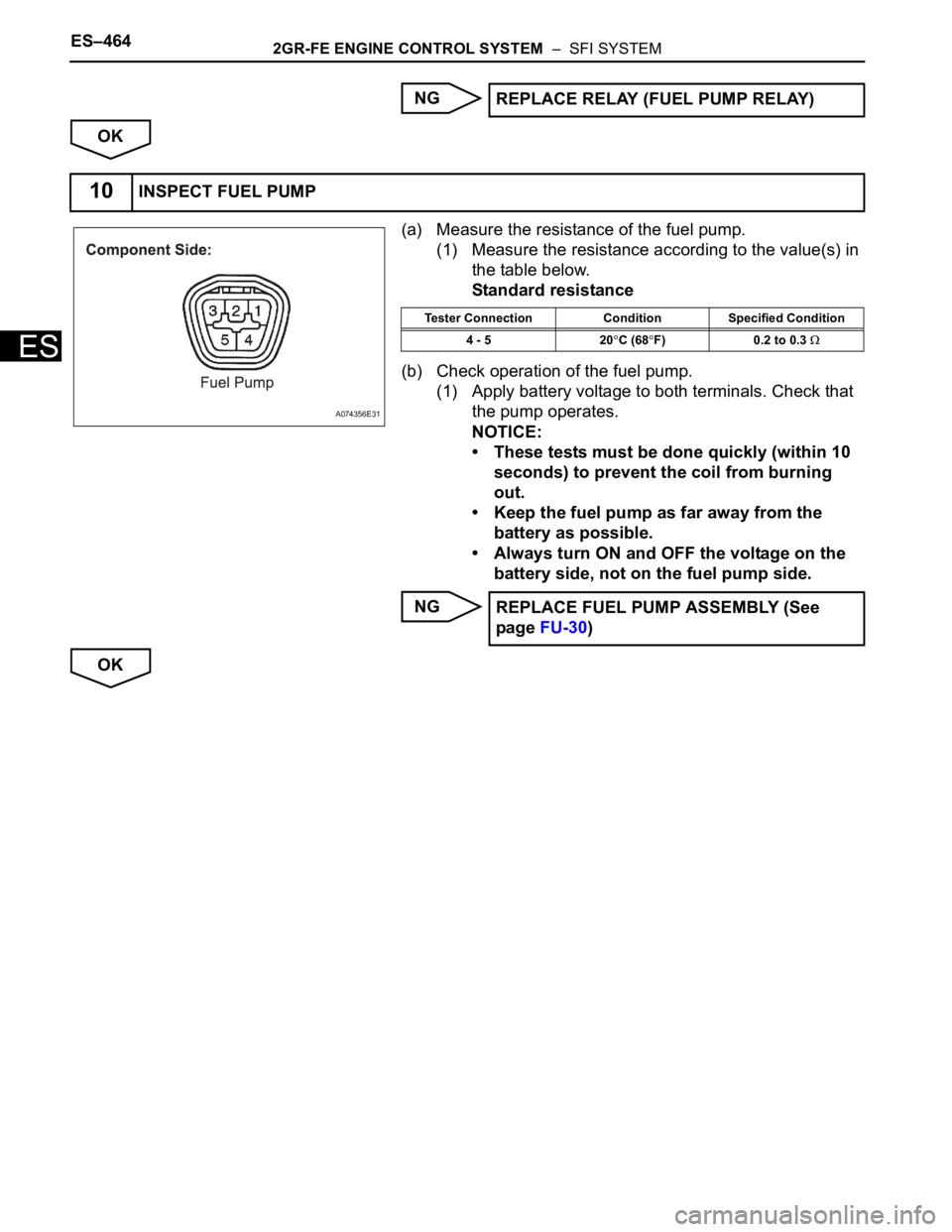
(a) Measure the resistance of the fuel pump.
(1) Measure the resistance according to the value(s) in
the table below.
Standard resistance
(b) Check operation of the fuel pump.
(1) Apply battery voltage to both terminals. Check that
the pump operates.
NOTICE:
• These tests must be done quickly (within 10
seconds) to prevent the coil from burning
out.
• Keep the fuel pump as far away from the
battery as possible.
• Always turn ON and OFF the voltage on the
battery side, not on the fuel pump side.
NG
OKREPLACE RELAY (FUEL PUMP RELAY)
10INSPECT FUEL PUMP
A074356E31
Tester Connection Condition Specified Condition
4 - 5 20
C (68F) 0.2 to 0.3
REPLACE FUEL PUMP ASSEMBLY (See
page FU-30)
Page 757 of 3000
2GR-FE ENGINE CONTROL SYSTEM – SFI SYSTEMES–471
ES
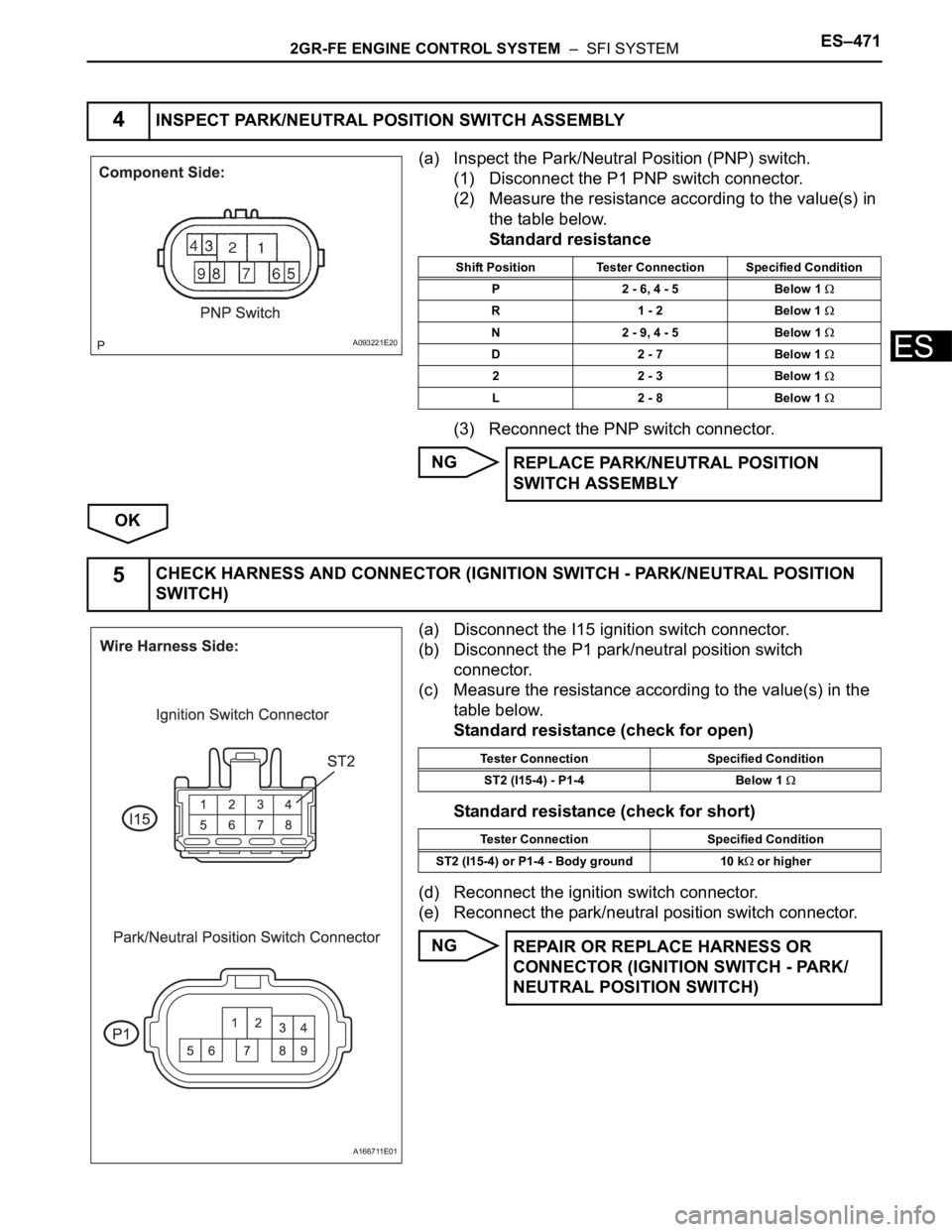
(a) Inspect the Park/Neutral Position (PNP) switch.
(1) Disconnect the P1 PNP switch connector.
(2) Measure the resistance according to the value(s) in
the table below.
Standard resistance
(3) Reconnect the PNP switch connector.
NG
OK
(a) Disconnect the I15 ignition switch connector.
(b) Disconnect the P1 park/neutral position switch
connector.
(c) Measure the resistance according to the value(s) in the
table below.
Standard resistance (check for open)
Standard resistance (check for short)
(d) Reconnect the ignition switch connector.
(e) Reconnect the park/neutral position switch connector.
NG
4INSPECT PARK/NEUTRAL POSITION SWITCH ASSEMBLY
A093221E20
Shift Position Tester Connection Specified Condition
P 2 - 6, 4 - 5 Below 1
R 1 - 2 Below 1
N 2 - 9, 4 - 5 Below 1
D 2 - 7 Below 1
2 2 - 3 Below 1
L 2 - 8 Below 1
REPLACE PARK/NEUTRAL POSITION
SWITCH ASSEMBLY
5CHECK HARNESS AND CONNECTOR (IGNITION SWITCH - PARK/NEUTRAL POSITION
SWITCH)
A166711E01
Tester Connection Specified Condition
ST2 (I15-4) - P1-4 Below 1
Tester Connection Specified Condition
ST2 (I15-4) or P1-4 - Body ground 10 k
or higher
REPAIR OR REPLACE HARNESS OR
CONNECTOR (IGNITION SWITCH - PARK/
NEUTRAL POSITION SWITCH)
Page 760 of 3000
ES–4742GR-FE ENGINE CONTROL SYSTEM – SFI SYSTEM
ES
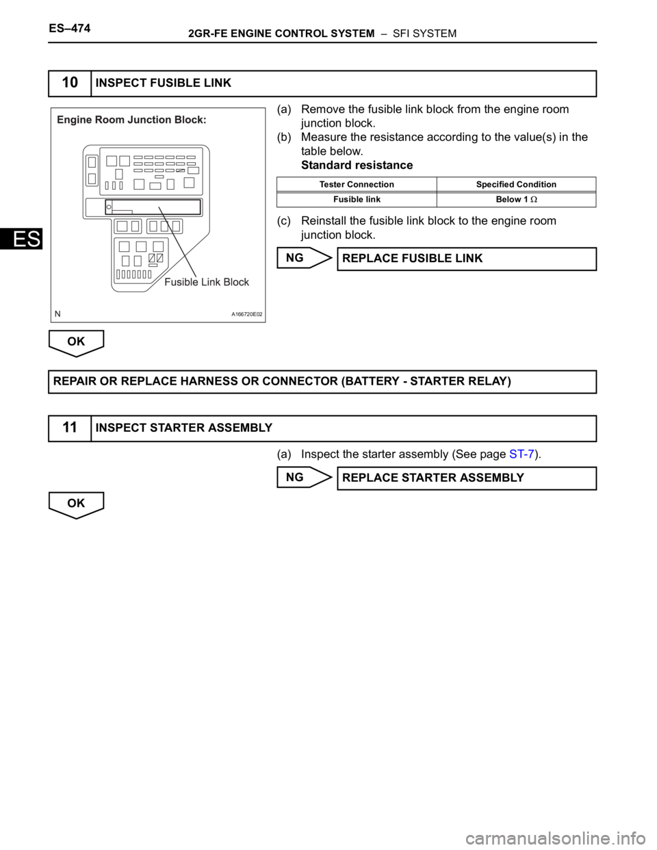
(a) Remove the fusible link block from the engine room
junction block.
(b) Measure the resistance according to the value(s) in the
table below.
Standard resistance
(c) Reinstall the fusible link block to the engine room
junction block.
NG
OK
(a) Inspect the starter assembly (See page ST-7).
NG
OK
10INSPECT FUSIBLE LINK
A166720E02
Tester Connection Specified Condition
Fusible link Below 1
REPLACE FUSIBLE LINK
REPAIR OR REPLACE HARNESS OR CONNECTOR (BATTERY - STARTER RELAY)
11INSPECT STARTER ASSEMBLY
REPLACE STARTER ASSEMBLY
Page 761 of 3000
2GR-FE ENGINE CONTROL SYSTEM – SFI SYSTEMES–475
ES
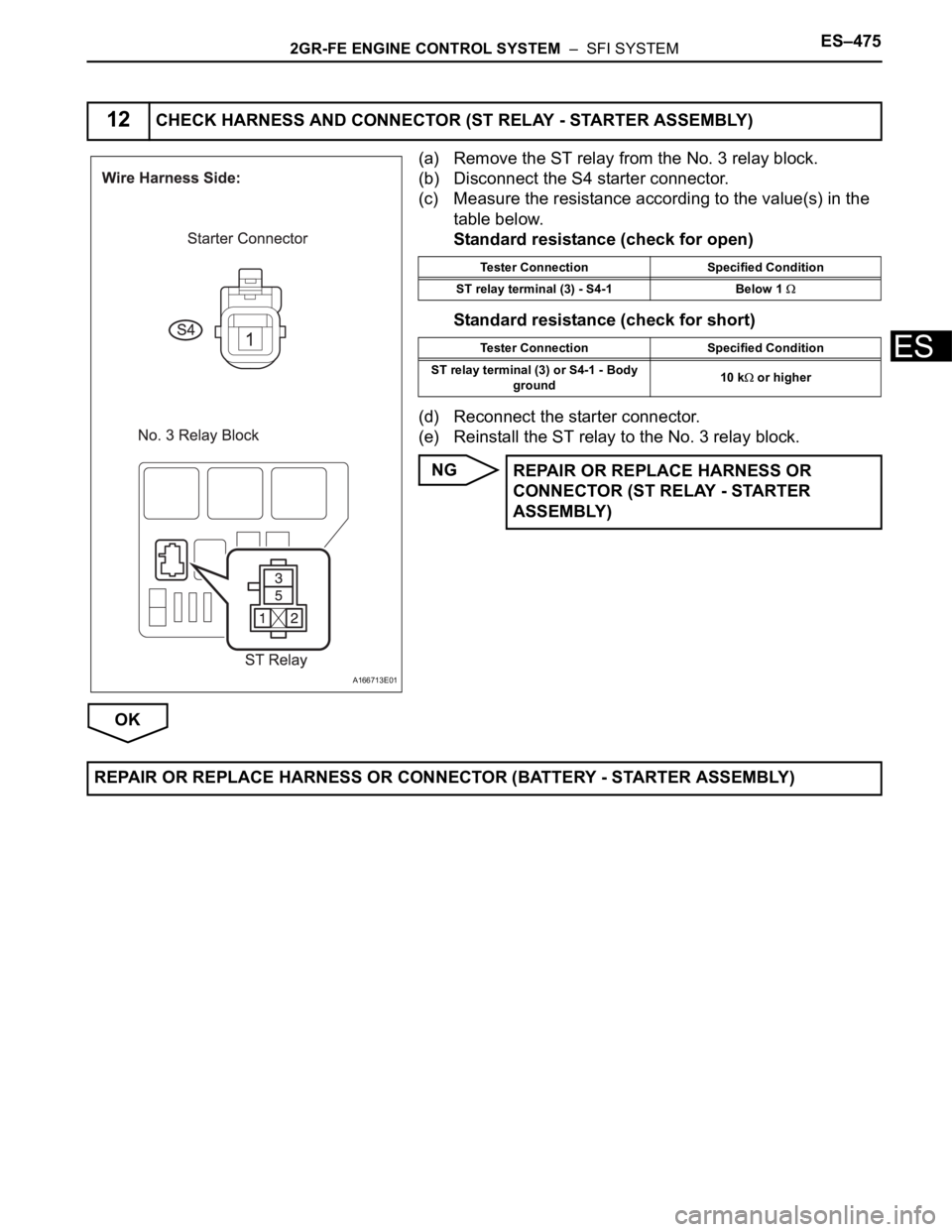
(a) Remove the ST relay from the No. 3 relay block.
(b) Disconnect the S4 starter connector.
(c) Measure the resistance according to the value(s) in the
table below.
Standard resistance (check for open)
Standard resistance (check for short)
(d) Reconnect the starter connector.
(e) Reinstall the ST relay to the No. 3 relay block.
NG
OK
12CHECK HARNESS AND CONNECTOR (ST RELAY - STARTER ASSEMBLY)
A166713E01
Tester Connection Specified Condition
ST relay terminal (3) - S4-1 Below 1
Tester Connection Specified Condition
ST relay terminal (3) or S4-1 - Body
ground10 k
or higher
REPAIR OR REPLACE HARNESS OR
CONNECTOR (ST RELAY - STARTER
ASSEMBLY)
REPAIR OR REPLACE HARNESS OR CONNECTOR (BATTERY - STARTER ASSEMBLY)