Page 781 of 3000
ES–4882GR-FE ENGINE CONTROL SYSTEM – CAMSHAFT TIMING OIL CONTROL VALVE
ASSEMBLY
ES
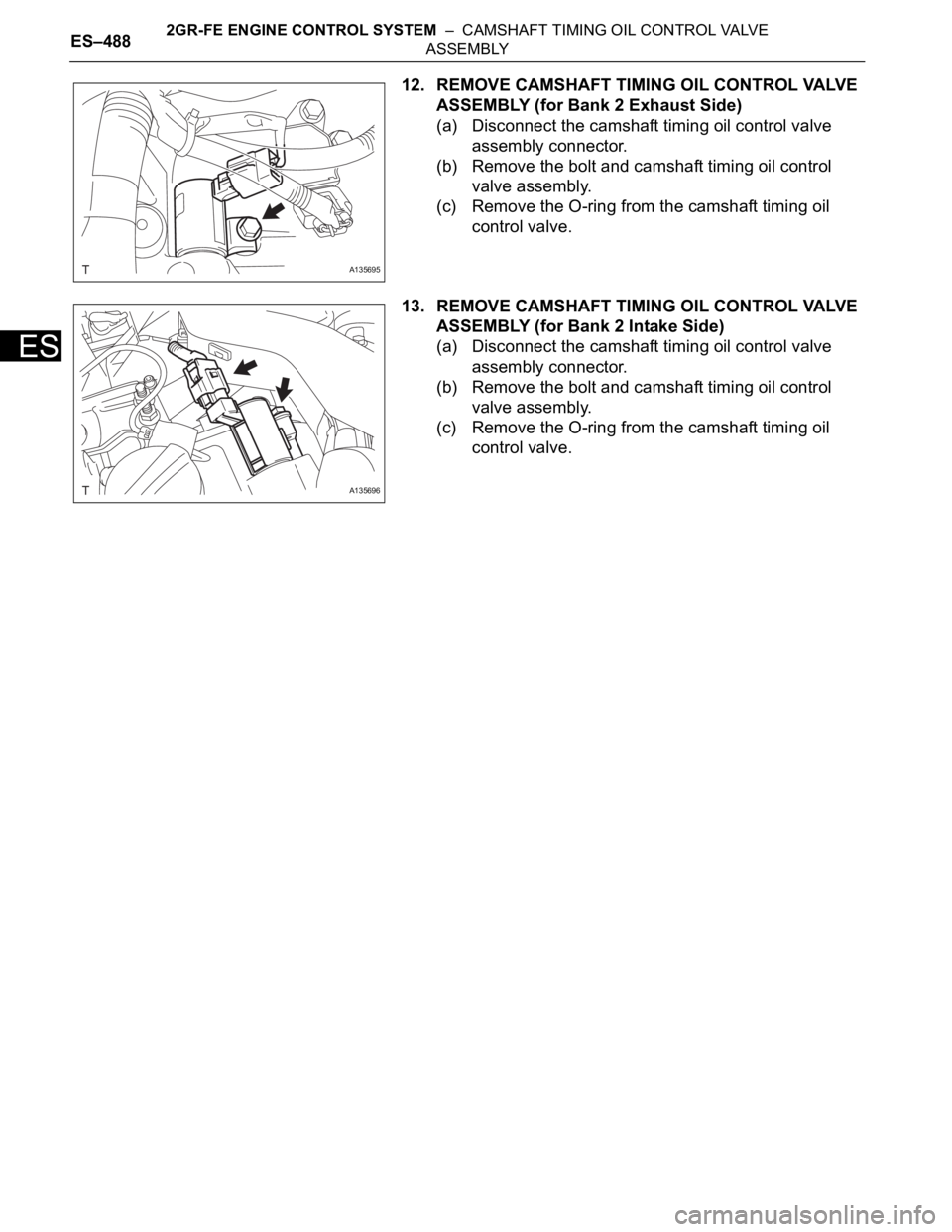
12. REMOVE CAMSHAFT TIMING OIL CONTROL VALVE
ASSEMBLY (for Bank 2 Exhaust Side)
(a) Disconnect the camshaft timing oil control valve
assembly connector.
(b) Remove the bolt and camshaft timing oil control
valve assembly.
(c) Remove the O-ring from the camshaft timing oil
control valve.
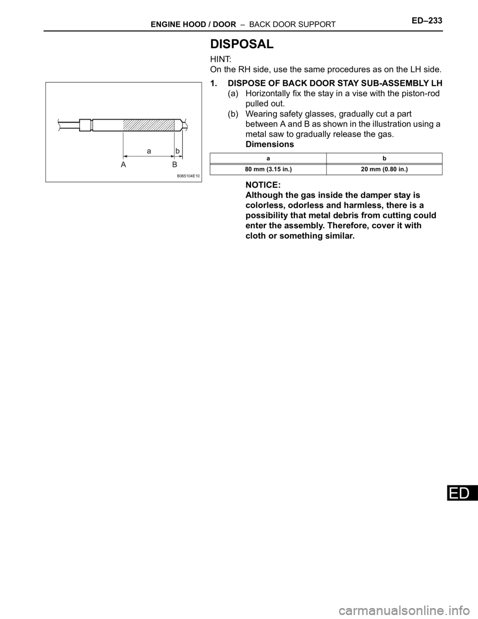
13. REMOVE CAMSHAFT TIMING OIL CONTROL VALVE
ASSEMBLY (for Bank 2 Intake Side)
(a) Disconnect the camshaft timing oil control valve
assembly connector.
(b) Remove the bolt and camshaft timing oil control
valve assembly.
(c) Remove the O-ring from the camshaft timing oil
control valve.
A135695
A135696
Page 782 of 3000
ED–232ENGINE HOOD / DOOR – BACK DOOR SUPPORT
ED
INSTALLATION
1. REMOVE BACK DOOR STAY SUB-ASSEMBLY LH
(a) Install the stay with the bolts to the door panel.
Torque: 19.5 N*m (200 kgf*cm, 14 ft.*lbf) for
door side
(b) Install the stay with the 2 bolts to the body panel.
Torque: 17.5 N*m (180 kgf*cm, 13 ft.*lbf) for
body side
Page 783 of 3000
ENGINE HOOD / DOOR – BACK DOOR SUPPORTED–233
ED
DISPOSAL
HINT:
On the RH side, use the same procedures as on the LH side.
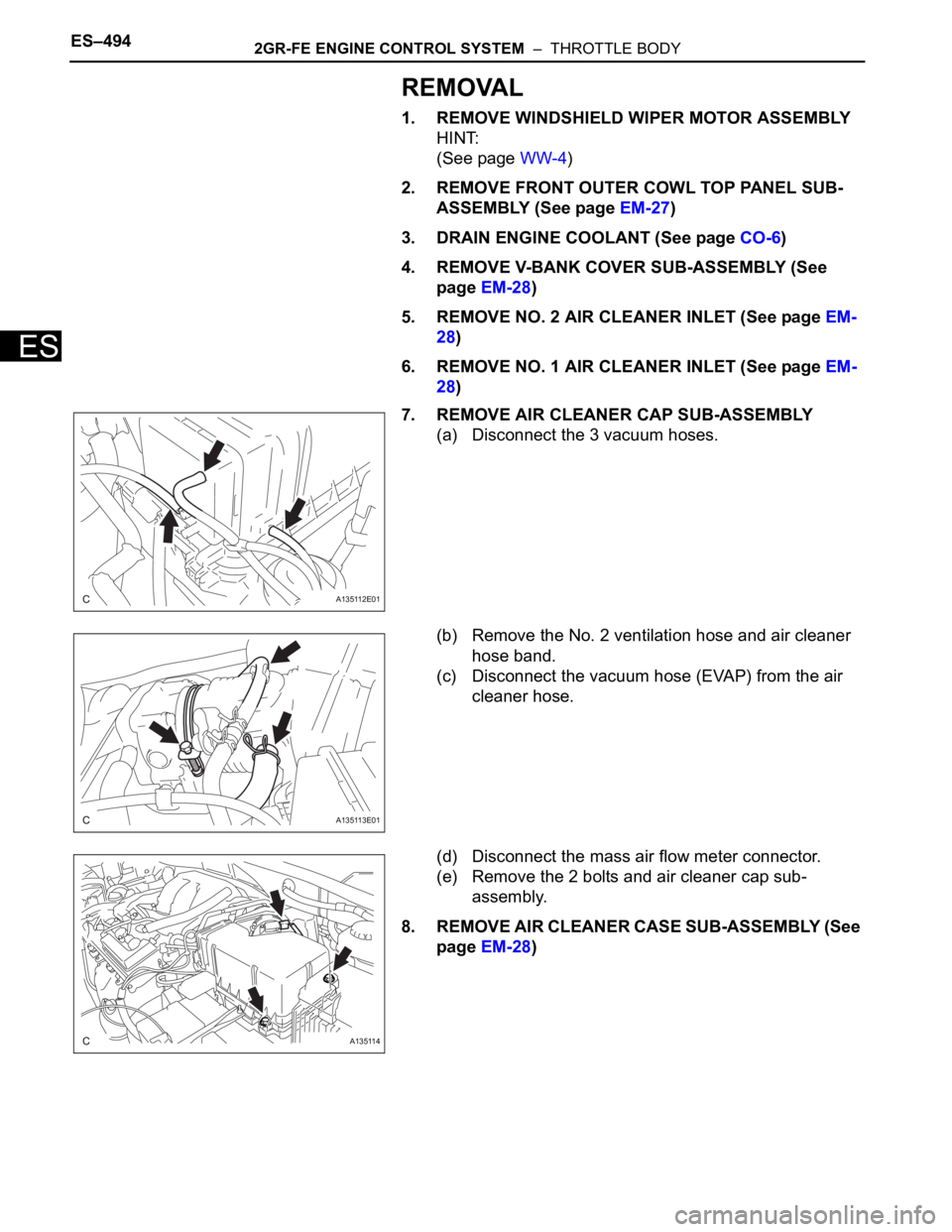
1. DISPOSE OF BACK DOOR STAY SUB-ASSEMBLY LH
(a) Horizontally fix the stay in a vise with the piston-rod
pulled out.
(b) Wearing safety glasses, gradually cut a part
between A and B as shown in the illustration using a
metal saw to gradually release the gas.
Dimensions
NOTICE:
Although the gas inside the damper stay is
colorless, odorless and harmless, there is a
possibility that metal debris from cutting could
enter the assembly. Therefore, cover it with
cloth or something similar.
B065104E10
ab
80 mm (3.15 in.) 20 mm (0.80 in.)
Page 790 of 3000
ES–4942GR-FE ENGINE CONTROL SYSTEM – THROTTLE BODY
ES
REMOVAL
1. REMOVE WINDSHIELD WIPER MOTOR ASSEMBLY
HINT:
(See page WW-4)
2. REMOVE FRONT OUTER COWL TOP PANEL SUB-
ASSEMBLY (See page EM-27)
3. DRAIN ENGINE COOLANT (See page CO-6)
4. REMOVE V-BANK COVER SUB-ASSEMBLY (See
page EM-28)
5. REMOVE NO. 2 AIR CLEANER INLET (See page EM-
28)
6. REMOVE NO. 1 AIR CLEANER INLET (See page EM-
28)
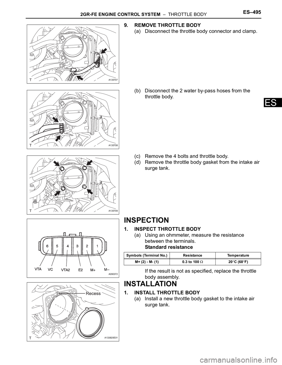
7. REMOVE AIR CLEANER CAP SUB-ASSEMBLY
(a) Disconnect the 3 vacuum hoses.
(b) Remove the No. 2 ventilation hose and air cleaner
hose band.
(c) Disconnect the vacuum hose (EVAP) from the air
cleaner hose.
(d) Disconnect the mass air flow meter connector.
(e) Remove the 2 bolts and air cleaner cap sub-
assembly.
8. REMOVE AIR CLEANER CASE SUB-ASSEMBLY (See
page EM-28)
A135112E01
A135113E01
A135114
Page 791 of 3000
2GR-FE ENGINE CONTROL SYSTEM – THROTTLE BODYES–495
ES
9. REMOVE THROTTLE BODY
(a) Disconnect the throttle body connector and clamp.
(b) Disconnect the 2 water by-pass hoses from the
throttle body.
(c) Remove the 4 bolts and throttle body.
(d) Remove the throttle body gasket from the intake air
surge tank.
INSPECTION
1. INSPECT THROTTLE BODY
(a) Using an ohmmeter, measure the resistance
between the terminals.
Standard resistance
If the result is not as specified, replace the throttle
body assembly.
INSTALLATION
1. INSTALL THROTTLE BODY
(a) Install a new throttle body gasket to the intake air
surge tank.
A135707
A135708
A135709
A090372
Symbols (Terminal No.) Resistance Temperature
M+ (2) - M- (1) 0.3 to 100
20C (68F)
A133820E01
Page 792 of 3000
ES–4962GR-FE ENGINE CONTROL SYSTEM – THROTTLE BODY
ES
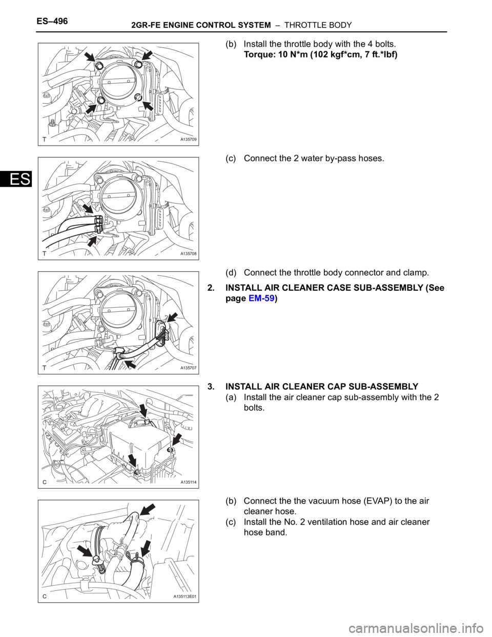
(b) Install the throttle body with the 4 bolts.
Torque: 10 N*m (102 kgf*cm, 7 ft.*lbf)
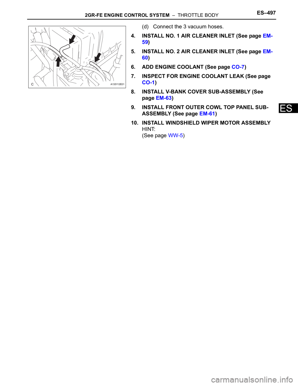
(c) Connect the 2 water by-pass hoses.
(d) Connect the throttle body connector and clamp.
2. INSTALL AIR CLEANER CASE SUB-ASSEMBLY (See
page EM-59)
3. INSTALL AIR CLEANER CAP SUB-ASSEMBLY
(a) Install the air cleaner cap sub-assembly with the 2
bolts.
(b) Connect the the vacuum hose (EVAP) to the air
cleaner hose.
(c) Install the No. 2 ventilation hose and air cleaner
hose band.
A135709
A135708
A135707
A135114
A135113E01
Page 793 of 3000
2GR-FE ENGINE CONTROL SYSTEM – THROTTLE BODYES–497
ES
(d) Connect the 3 vacuum hoses.
4. INSTALL NO. 1 AIR CLEANER INLET (See page EM-
59)
5. INSTALL NO. 2 AIR CLEANER INLET (See page EM-
60)
6. ADD ENGINE COOLANT (See page CO-7)
7. INSPECT FOR ENGINE COOLANT LEAK (See page
CO-1)
8. INSTALL V-BANK COVER SUB-ASSEMBLY (See
page EM-63)
9. INSTALL FRONT OUTER COWL TOP PANEL SUB-
ASSEMBLY (See page EM-61)
10. INSTALL WINDSHIELD WIPER MOTOR ASSEMBLY
HINT:
(See page WW-5)
A135112E01
Page 799 of 3000
ES–4982GR-FE ENGINE CONTROL SYSTEM – ECM
ES
REMOVAL
1. REMOVE GLOVE COMPARTMENT DOOR
ASSEMBLY
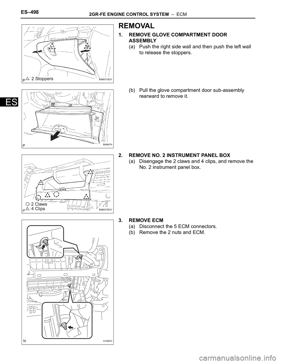
(a) Push the right side wall and then push the left wall
to release the stoppers.
(b) Pull the glove compartment door sub-assembly
rearward to remove it.
2. REMOVE NO. 2 INSTRUMENT PANEL BOX
(a) Disengage the 2 claws and 4 clips, and remove the
No. 2 instrument panel box.
3. REMOVE ECM
(a) Disconnect the 5 ECM connectors.
(b) Remove the 2 nuts and ECM.
B066073E01
B066074
B066075E01
A162672