Page 876 of 3000
2GR-FE ENGINE MECHANICAL – ENGINE ASSEMBLYEM–59
EM
81. INSTALL AIR CLEANER BRACKET
(a) Remove the 2 bolts and air cleaner bracket.
Torque: 12 N*m (122 kgf*cm, 9 ft.*lbf)
82. INSTALL BATTERY
(a) Install the battery and battery tray.
(b) Install the battery clamp with the bolt and nut.
Torque: Bolt
9.0 N*m (92 kgf*cm, 80 in.*lbf)
Nut
3.5 N*m (36 kgf*cm, 31 in.*lbf)
(c) Connect the positive battery terminal.
(d) Connect the negative battery terminal.
83. INSTALL AIR CLEANER CASE SUB-ASSEMBLY
(a) Install the air cleaner case with the 3 bolts.
Torque: 5.0 N*m (51 kgf*cm, 44 in.*lbf)
(b) Connect the vacuum hose.
(c) Connect the vacuum switching valve connector.
84. INSTALL AIR CLEANER FILTER ELEMENT SUB-
ASSEMBLY
(a) Install the air cleaner filter element sub-assembly.
85. INSTALL AIR CLEANER CAP SUB-ASSEMBLY (See
page IT-5)
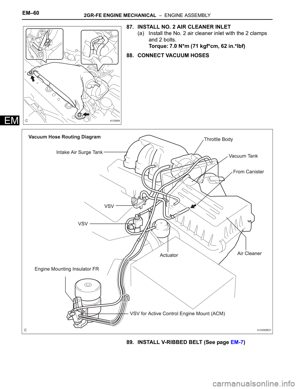
86. INSTALL NO. 1 AIR CLEANER INLET
(a) Install the No. 1 air cleaner inlet with the bolt.
Torque: 7.0 N*m (71 kgf*cm, 62 in.*lbf)
A155041
A155033
A155039
A155040
Page 877 of 3000
EM–602GR-FE ENGINE MECHANICAL – ENGINE ASSEMBLY
EM
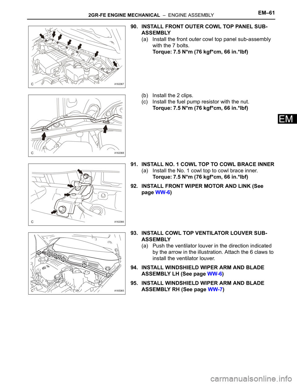
87. INSTALL NO. 2 AIR CLEANER INLET
(a) Install the No. 2 air cleaner inlet with the 2 clamps
and 2 bolts.
Torque: 7.0 N*m (71 kgf*cm, 62 in.*lbf)
88. CONNECT VACUUM HOSES
89. INSTALL V-RIBBED BELT (See page EM-7)
A133004
A133002E01
Page 878 of 3000
2GR-FE ENGINE MECHANICAL – ENGINE ASSEMBLYEM–61
EM
90. INSTALL FRONT OUTER COWL TOP PANEL SUB-
ASSEMBLY
(a) Install the front outer cowl top panel sub-assembly
with the 7 bolts.
Torque: 7.5 N*m (76 kgf*cm, 66 in.*lbf)
(b) Install the 2 clips.
(c) Install the fuel pump resistor with the nut.
Torque: 7.5 N*m (76 kgf*cm, 66 in.*lbf)
91. INSTALL NO. 1 COWL TOP TO COWL BRACE INNER
(a) Install the No. 1 cowl top to cowl brace inner.
Torque: 7.5 N*m (76 kgf*cm, 66 in.*lbf)
92. INSTALL FRONT WIPER MOTOR AND LINK (See
page WW-6)
93. INSTALL COWL TOP VENTILATOR LOUVER SUB-
ASSEMBLY
(a) Push the ventilator louver in the direction indicated
by the arrow in the illustration. Attach the 6 claws to
install the ventilator louver.
94. INSTALL WINDSHIELD WIPER ARM AND BLADE
ASSEMBLY LH (See page WW-6)
95. INSTALL WINDSHIELD WIPER ARM AND BLADE
ASSEMBLY RH (See page WW-7)
A162367
A162368
A162366
A165365
Page 879 of 3000
EM–622GR-FE ENGINE MECHANICAL – ENGINE ASSEMBLY
EM
96. INSTALL FRONT WIPER ARM HEAD CAP
(a) Install the front wiper arm head caps.
97. INSTALL FRONT WHEELS
Torque: 103 N*m (1050 kgf*cm, 76 ft.*lbf)
98. ADD ENGINE OIL (See page LU-6)
99. ADD ENGINE COOLANT (See page CO-7)
100. ADD AUTOMATIC TRANSAXLE FLUID
101. CHECK AUTOMATIC TRANSAXLE FLUID (See page
AX-123)
102. ADD POWER STEERING FLUID
103. BLEED POWER STEERING FLUID (See page PS-6)
104. INSPECT FOR FUEL LEAK (See page FU-7)
105. INSPECT FOR ENGINE OIL LEAK
106. INSPECT FOR ENGINE COOLANT LEAK (See page
CO-1)
107. INSPECT FOR EXHAUST GAS LEAK
108. CHECK SHIFT LEVER POSITION (See page AX-127)
109. CHECK AND ADJUST FRONT WHEEL ALIGNMENT
HINT:
(See page SP-4).
110. CHECK IGNITION TIMING (See page EM-1)
111. CHECK ENGINE IDLE SPEED (See page EM-2)
112. CHECK CO/HC (See page EM-4)
113. CHECK FUNCTION OF THROTTLE BODY
ASSEMBLY (See page ES-493)
114. INSTALL FRONT FENDER APRON SEAL RH
(a) Install the front fender apron seal RH with the 2
bolts and clip.
115. INSTALL FRONT FENDER APRON SEAL LH
(a) Install the front fender apron seal LH with the 2 bolts
and clip.
A165364E01
A162371
A162370
Page 880 of 3000
2GR-FE ENGINE MECHANICAL – ENGINE ASSEMBLYEM–63
EM
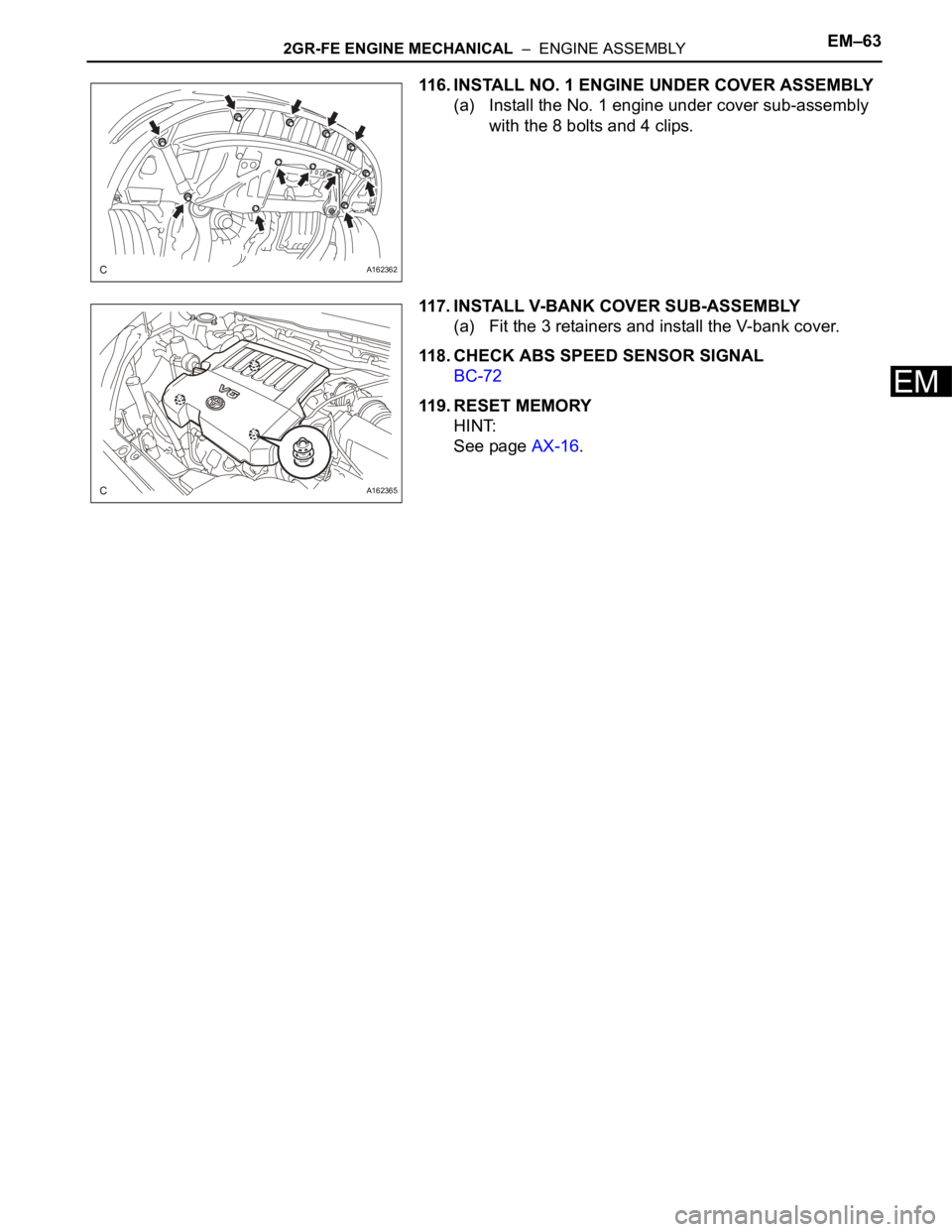
116. INSTALL NO. 1 ENGINE UNDER COVER ASSEMBLY
(a) Install the No. 1 engine under cover sub-assembly
with the 8 bolts and 4 clips.
117. INSTALL V-BANK COVER SUB-ASSEMBLY
(a) Fit the 3 retainers and install the V-bank cover.
118. CHECK ABS SPEED SENSOR SIGNAL
BC-72
119. RESET MEMORY
HINT:
See page AX-16.
A162362
A162365
Page 881 of 3000
EM–762GR-FE ENGINE MECHANICAL – ENGINE UNIT
EM
DISASSEMBLY
1. REMOVE OIL FILLER CAP SUB-ASSEMBLY
(a) Remove the oil filler cap sub-assembly and oil filler
gasket.
2. REMOVE SPARK PLUG
(a) Remove the spark plugs.
3. REMOVE OIL PAN DRAIN PLUG
(a) Remove the oil pan drain plug and oil pan drain plug
gasket.
4. REMOVE VENTILATION VALVE SUB-ASSEMBLY
(a) Remove the ventilation valve sub-assembly.
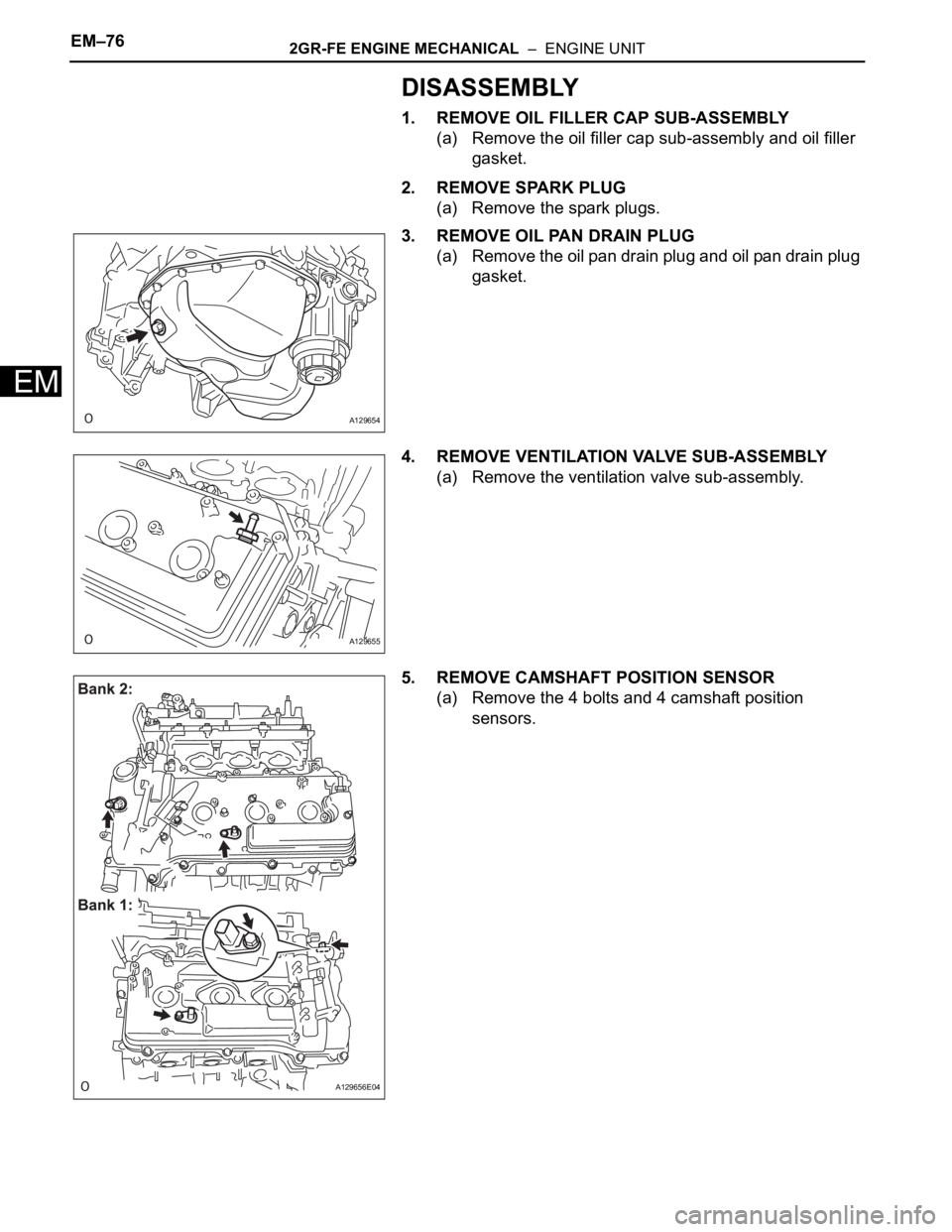
5. REMOVE CAMSHAFT POSITION SENSOR
(a) Remove the 4 bolts and 4 camshaft position
sensors.
A129654
A129655
A129656E04
Page 882 of 3000
2GR-FE ENGINE MECHANICAL – ENGINE UNITEM–77
EM
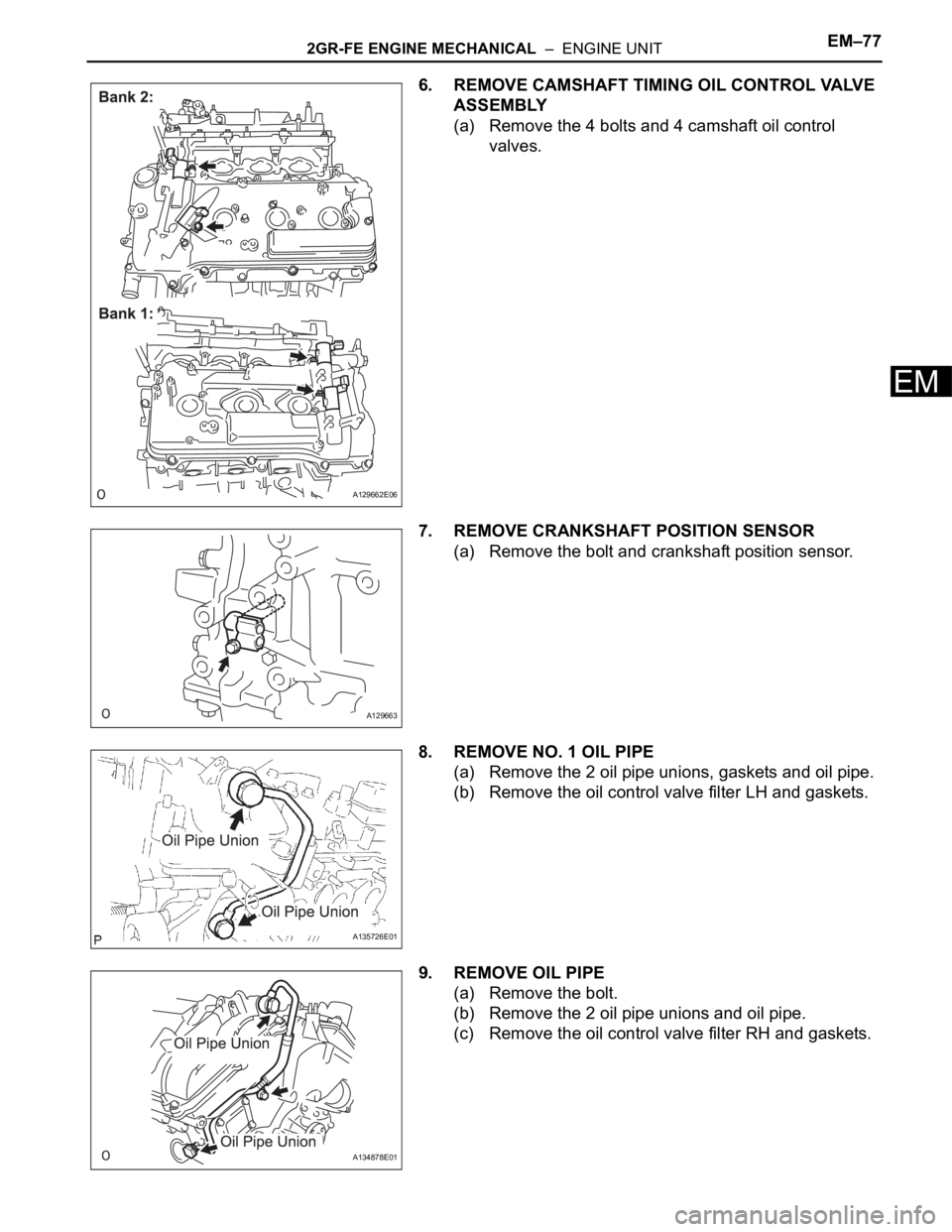
6. REMOVE CAMSHAFT TIMING OIL CONTROL VALVE
ASSEMBLY
(a) Remove the 4 bolts and 4 camshaft oil control
valves.
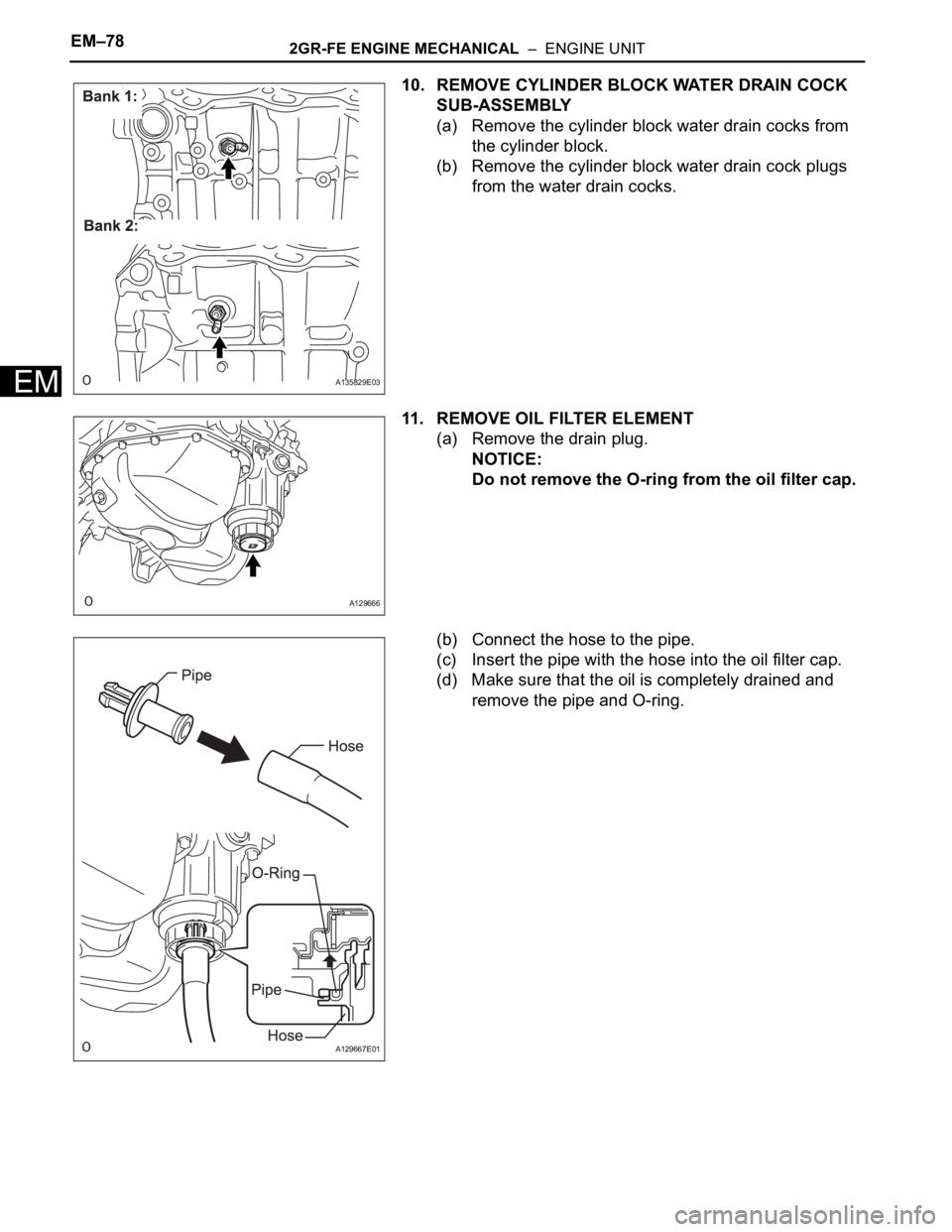
7. REMOVE CRANKSHAFT POSITION SENSOR
(a) Remove the bolt and crankshaft position sensor.
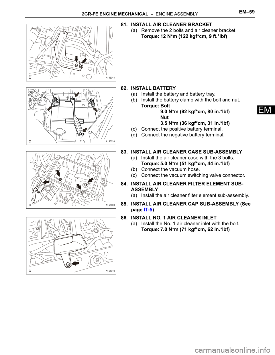
8. REMOVE NO. 1 OIL PIPE
(a) Remove the 2 oil pipe unions, gaskets and oil pipe.
(b) Remove the oil control valve filter LH and gaskets.
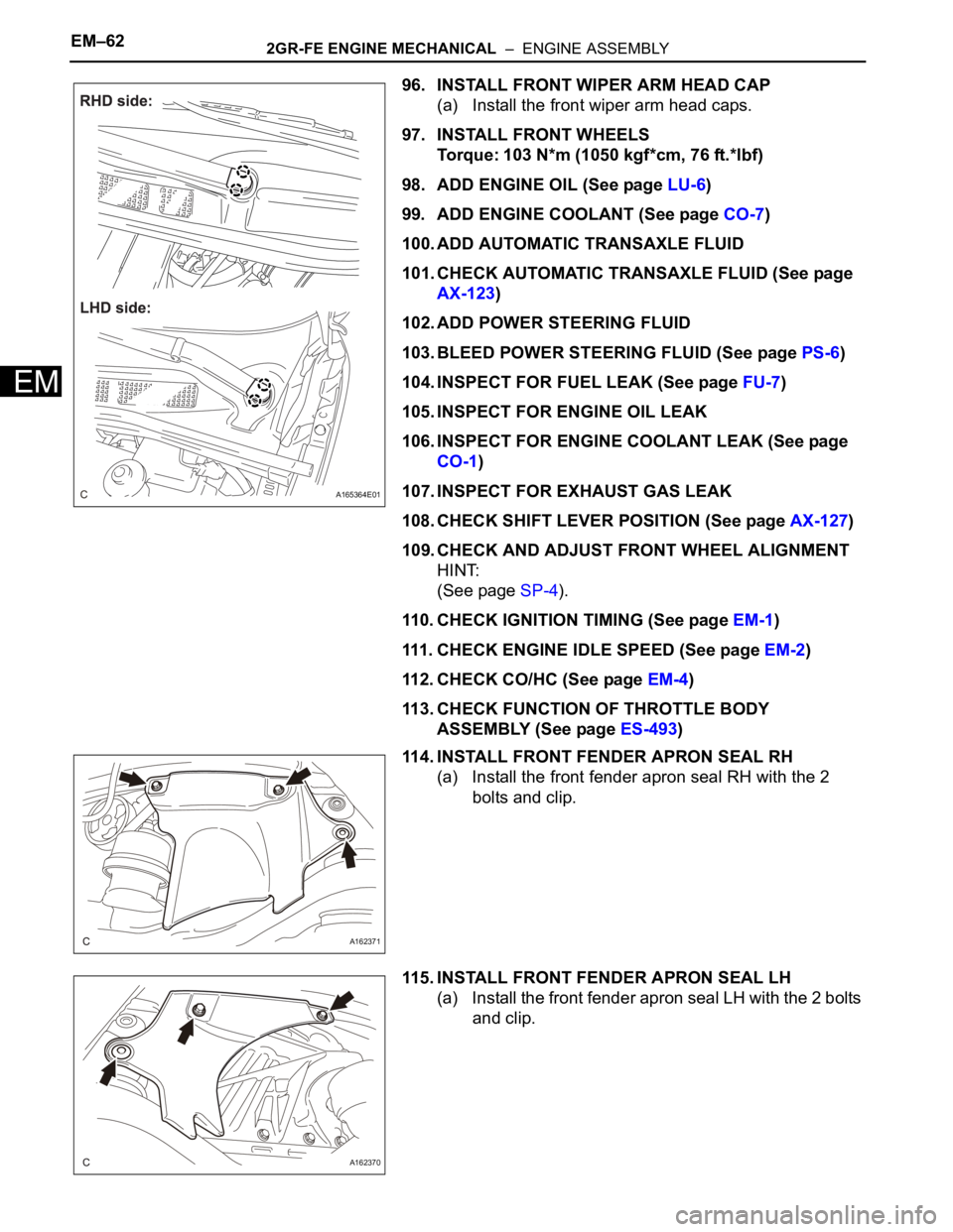
9. REMOVE OIL PIPE
(a) Remove the bolt.
(b) Remove the 2 oil pipe unions and oil pipe.
(c) Remove the oil control valve filter RH and gaskets.
A129662E06
A129663
A135726E01
A134878E01
Page 883 of 3000
EM–782GR-FE ENGINE MECHANICAL – ENGINE UNIT
EM
10. REMOVE CYLINDER BLOCK WATER DRAIN COCK
SUB-ASSEMBLY
(a) Remove the cylinder block water drain cocks from
the cylinder block.
(b) Remove the cylinder block water drain cock plugs
from the water drain cocks.
11. REMOVE OIL FILTER ELEMENT
(a) Remove the drain plug.
NOTICE:
Do not remove the O-ring from the oil filter cap.
(b) Connect the hose to the pipe.
(c) Insert the pipe with the hose into the oil filter cap.
(d) Make sure that the oil is completely drained and
remove the pipe and O-ring.
A135829E03
A129666
A129667E01