Page 762 of 3000
ES–4762GR-FE ENGINE CONTROL SYSTEM – SFI SYSTEM
ES
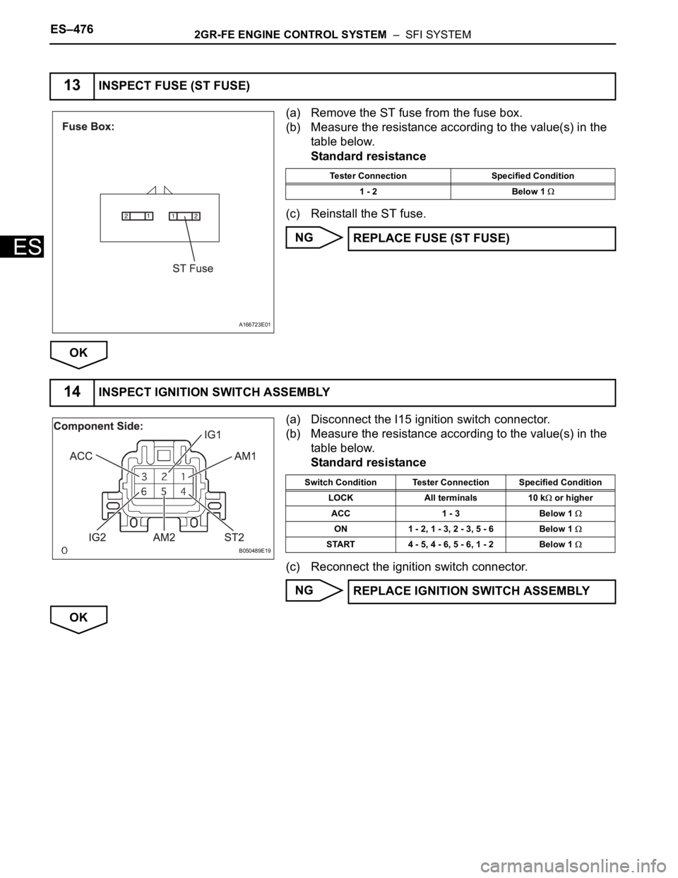
(a) Remove the ST fuse from the fuse box.
(b) Measure the resistance according to the value(s) in the
table below.
Standard resistance
(c) Reinstall the ST fuse.
NG
OK
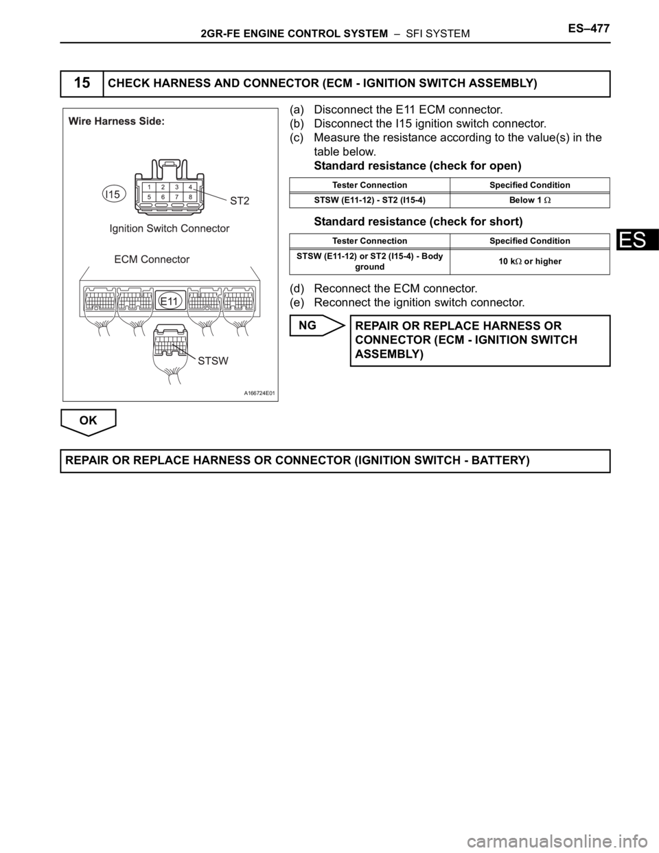
(a) Disconnect the I15 ignition switch connector.
(b) Measure the resistance according to the value(s) in the
table below.
Standard resistance
(c) Reconnect the ignition switch connector.
NG
OK
13INSPECT FUSE (ST FUSE)
A166723E01
Tester Connection Specified Condition
1 - 2 Below 1
REPLACE FUSE (ST FUSE)
14INSPECT IGNITION SWITCH ASSEMBLY
B050489E19
Switch Condition Tester Connection Specified Condition
LOCK All terminals 10 k
or higher
ACC 1 - 3 Below 1
ON 1 - 2, 1 - 3, 2 - 3, 5 - 6 Below 1
START 4 - 5, 4 - 6, 5 - 6, 1 - 2 Below 1
REPLACE IGNITION SWITCH ASSEMBLY
Page 763 of 3000
2GR-FE ENGINE CONTROL SYSTEM – SFI SYSTEMES–477
ES
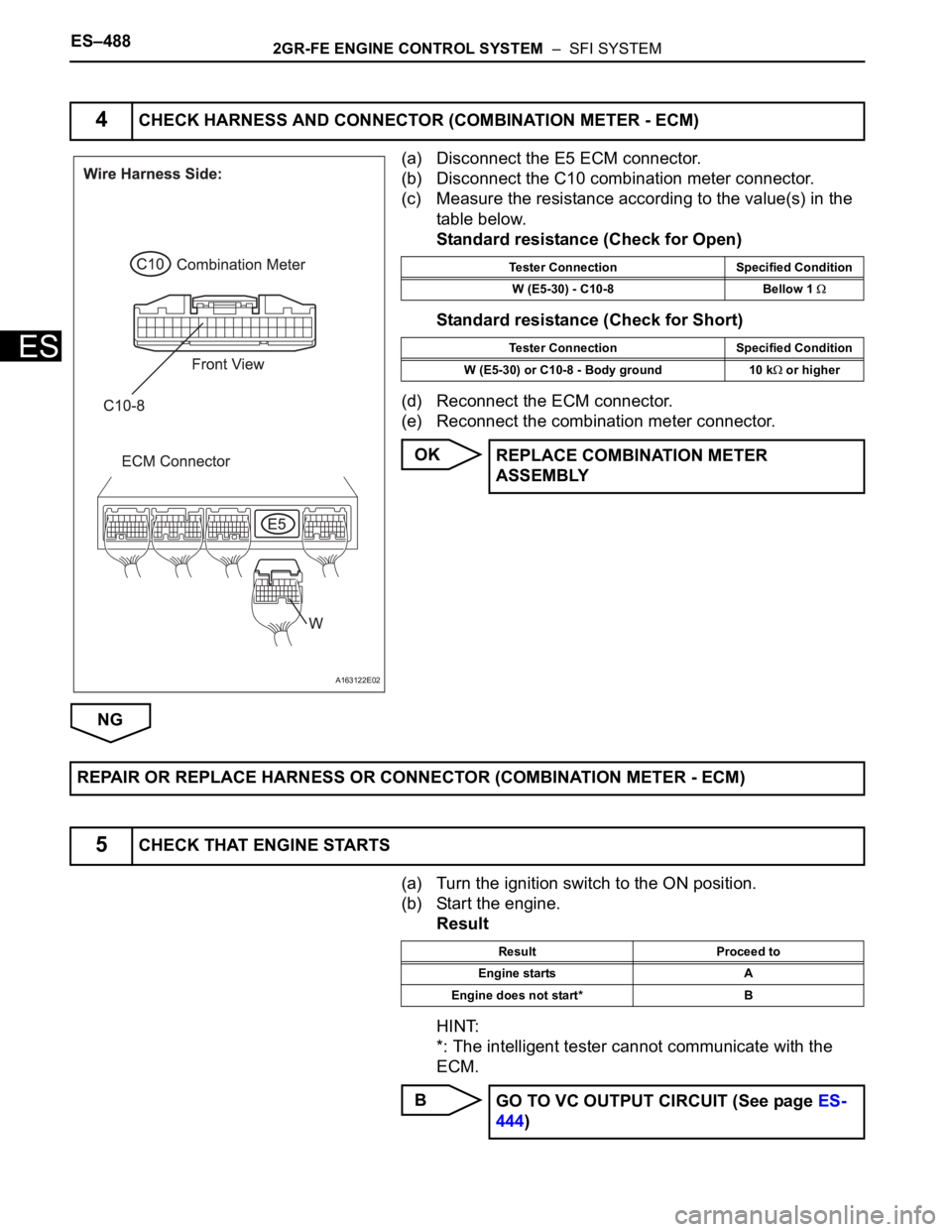
(a) Disconnect the E11 ECM connector.
(b) Disconnect the I15 ignition switch connector.
(c) Measure the resistance according to the value(s) in the
table below.
Standard resistance (check for open)
Standard resistance (check for short)
(d) Reconnect the ECM connector.
(e) Reconnect the ignition switch connector.
NG
OK
15CHECK HARNESS AND CONNECTOR (ECM - IGNITION SWITCH ASSEMBLY)
A166724E01
Tester Connection Specified Condition
STSW (E11-12) - ST2 (I15-4) Below 1
Tester Connection Specified Condition
STSW (E11-12) or ST2 (I15-4) - Body
ground10 k
or higher
REPAIR OR REPLACE HARNESS OR
CONNECTOR (ECM - IGNITION SWITCH
ASSEMBLY)
REPAIR OR REPLACE HARNESS OR CONNECTOR (IGNITION SWITCH - BATTERY)
Page 770 of 3000
ES–4882GR-FE ENGINE CONTROL SYSTEM – SFI SYSTEM
ES
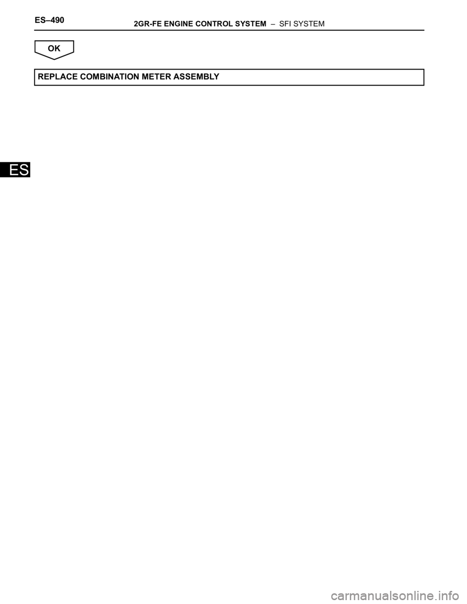
(a) Disconnect the E5 ECM connector.
(b) Disconnect the C10 combination meter connector.
(c) Measure the resistance according to the value(s) in the
table below.
Standard resistance (Check for Open)
Standard resistance (Check for Short)
(d) Reconnect the ECM connector.
(e) Reconnect the combination meter connector.
OK
NG
(a) Turn the ignition switch to the ON position.
(b) Start the engine.
Result
HINT:
*: The intelligent tester cannot communicate with the
ECM.
B
4CHECK HARNESS AND CONNECTOR (COMBINATION METER - ECM)
A163122E02
Tester Connection Specified Condition
W (E5-30) - C10-8 Bellow 1
Tester Connection Specified Condition
W (E5-30) or C10-8 - Body ground 10 k
or higher
REPLACE COMBINATION METER
ASSEMBLY
REPAIR OR REPLACE HARNESS OR CONNECTOR (COMBINATION METER - ECM)
5CHECK THAT ENGINE STARTS
Result Proceed to
Engine starts A
Engine does not start* B
GO TO VC OUTPUT CIRCUIT (See page ES-
444)
Page 772 of 3000
ES–4902GR-FE ENGINE CONTROL SYSTEM – SFI SYSTEM
ES
OK
REPLACE COMBINATION METER ASSEMBLY
Page 773 of 3000
ED–214ENGINE HOOD / DOOR – BACK DOOR
ED
DISASSEMBLY
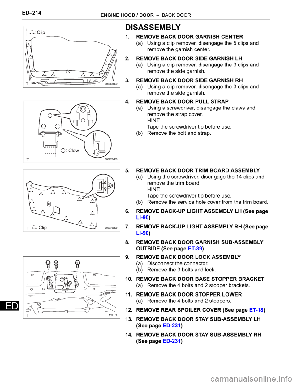
1. REMOVE BACK DOOR GARNISH CENTER
(a) Using a clip remover, disengage the 5 clips and
remove the garnish center.
2. REMOVE BACK DOOR SIDE GARNISH LH
(a) Using a clip remover, disengage the 3 clips and
remove the side garnish.
3. REMOVE BACK DOOR SIDE GARNISH RH
(a) Using a clip remover, disengage the 3 clips and
remove the side garnish.
4. REMOVE BACK DOOR PULL STRAP
(a) Using a screwdriver, disengage the claws and
remove the strap cover.
HINT:
Tape the screwdriver tip before use.
(b) Remove the bolt and strap.
5. REMOVE BACK DOOR TRIM BOARD ASSEMBLY
(a) Using the screwdriver, disengage the 14 clips and
remove the trim board.
HINT:
Tape the screwdriver tip before use.
(b) Remove the service hole cover from the trim board.
6. REMOVE BACK-UP LIGHT ASSEMBLY LH (See page
LI-90)
7. REMOVE BACK-UP LIGHT ASSEMBLY RH (See page
LI-90)
8. REMOVE BACK DOOR GARNISH SUB-ASSEMBLY
OUTSIDE (See page ET-39)
9. REMOVE BACK DOOR LOCK ASSEMBLY
(a) Disconnect the connector.
(b) Remove the 3 bolts and lock.
10. REMOVE BACK DOOR BASE STOPPER BRACKET
(a) Remove the 4 bolts and 2 stopper brackets.
11. REMOVE BACK DOOR STOPPER LOWER
(a) Remove the 4 bolts and 2 stoppers.
12. REMOVE REAR SPOILER COVER (See page ET-18)
13. REMOVE BACK DOOR STAY SUB-ASSEMBLY LH
(See page ED-231)
14. REMOVE BACK DOOR STAY SUB-ASSEMBLY RH
(See page ED-231)
B069688E01
B067784E01
B067783E01
B067787
Page 774 of 3000
ENGINE HOOD / DOOR – BACK DOORED–215
ED
ADJUSTMENT
HINT:
• On the RH side, use the same procedures as on the LH
side.
• Since a centering bolt is used as door hinge mounting
bolts on the body side and the door side, the door cannot
be adjusted with them on. Substitute a bolt with a washer
for the centering bolt.
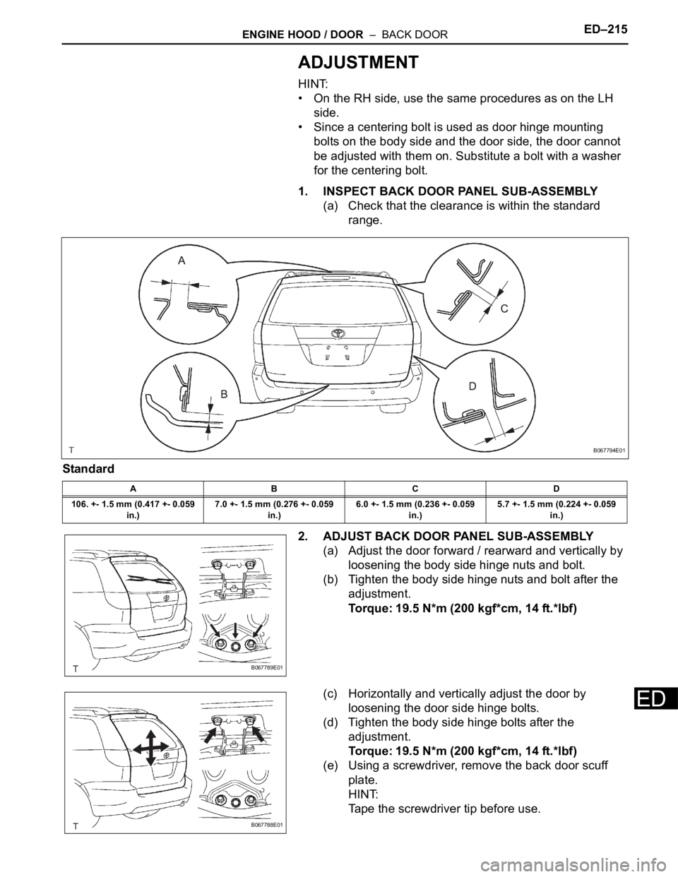
1. INSPECT BACK DOOR PANEL SUB-ASSEMBLY
(a) Check that the clearance is within the standard
range.
Standard
2. ADJUST BACK DOOR PANEL SUB-ASSEMBLY
(a) Adjust the door forward / rearward and vertically by
loosening the body side hinge nuts and bolt.
(b) Tighten the body side hinge nuts and bolt after the
adjustment.
Torque: 19.5 N*m (200 kgf*cm, 14 ft.*lbf)
(c) Horizontally and vertically adjust the door by
loosening the door side hinge bolts.
(d) Tighten the body side hinge bolts after the
adjustment.
Torque: 19.5 N*m (200 kgf*cm, 14 ft.*lbf)
(e) Using a screwdriver, remove the back door scuff
plate.
HINT:
Tape the screwdriver tip before use.
ABCD
106. +- 1.5 mm (0.417 +- 0.059
in.)7.0 +- 1.5 mm (0.276 +- 0.059
in.)6.0 +- 1.5 mm (0.236 +- 0.059
in.)5.7 +- 1.5 mm (0.224 +- 0.059
in.)
B067794E01
B067789E01
B067788E01
Page 779 of 3000
ES–4862GR-FE ENGINE CONTROL SYSTEM – CAMSHAFT TIMING OIL CONTROL VALVE
ASSEMBLY
ES
ON-VEHICLE INSPECTION
1. INSPECT CAMSHAFT TIMING CONTROL VALVE
ASSEMBLY
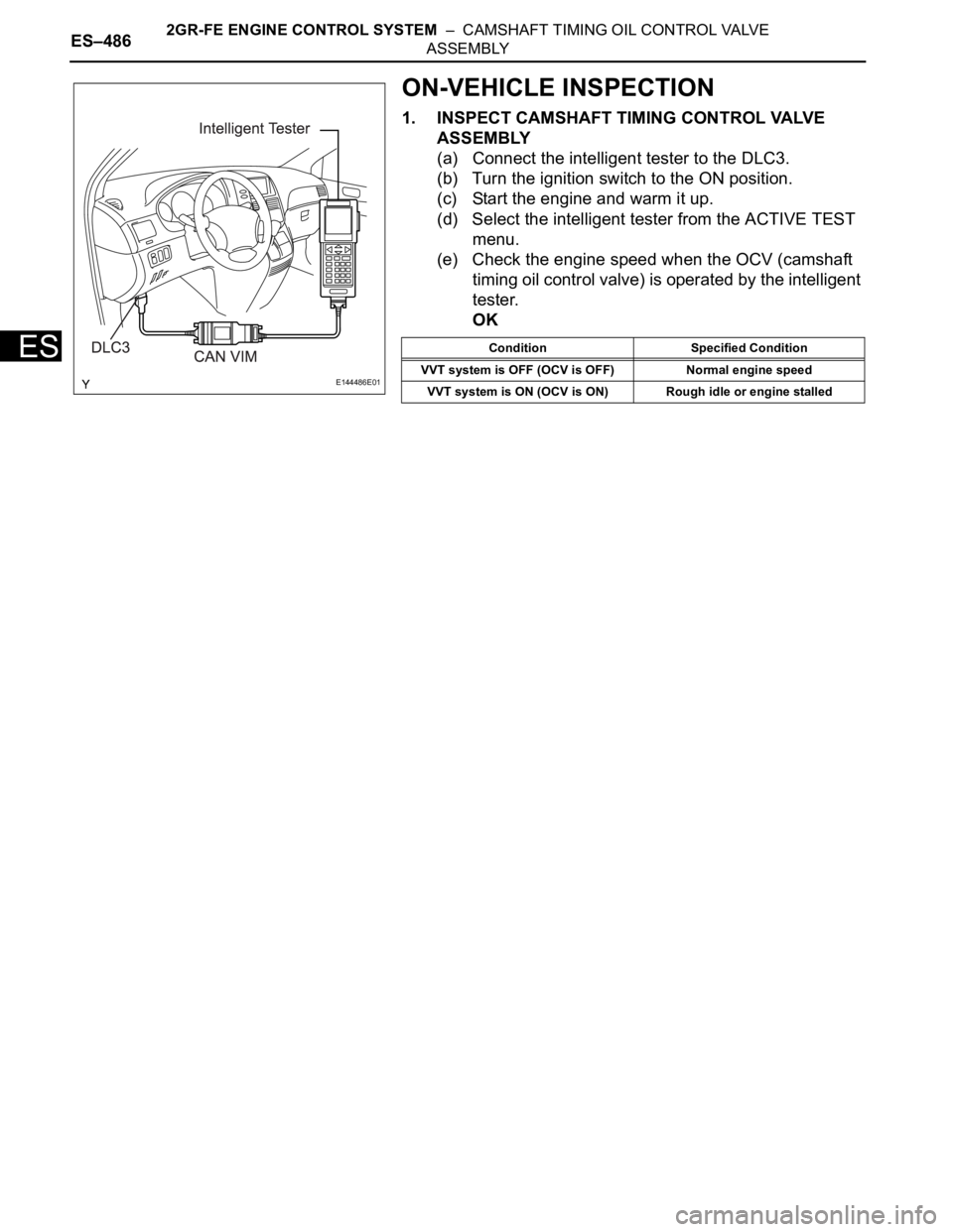
(a) Connect the intelligent tester to the DLC3.
(b) Turn the ignition switch to the ON position.
(c) Start the engine and warm it up.
(d) Select the intelligent tester from the ACTIVE TEST
menu.
(e) Check the engine speed when the OCV (camshaft
timing oil control valve) is operated by the intelligent
tester.
OK
E144486E01
Condition Specified Condition
VVT system is OFF (OCV is OFF) Normal engine speed
VVT system is ON (OCV is ON) Rough idle or engine stalled
Page 780 of 3000
2GR-FE ENGINE CONTROL SYSTEM – CAMSHAFT TIMING OIL CONTROL VALVE
ASSEMBLYES–487
ES
REMOVAL
1. REMOVE WINDSHIELD WIPER MOTOR ASSEMBLY
HINT:
(See page WW-4)
2. REMOVE FRONT OUTER COWL TOP PANEL SUB-
ASSEMBLY (See page EM-27)
3. DRAIN ENGINE COOLANT (See page CO-6)
4. REMOVE V-BANK COVER SUB-ASSEMBLY (See
page EM-28)
5. REMOVE NO. 2 AIR CLEANER INLET (See page EM-
28)
6. REMOVE NO. 1 AIR CLEANER INLET (See page EM-
28)
7. REMOVE AIR CLEANER CAP SUB-ASSEMBLY (See
page ES-493)
8. REMOVE AIR CLEANER CASE SUB-ASSEMBLY (See
page EM-28)
9. REMOVE INTAKE AIR SURGE TANK ASSEMBLY
(See page ES-521)
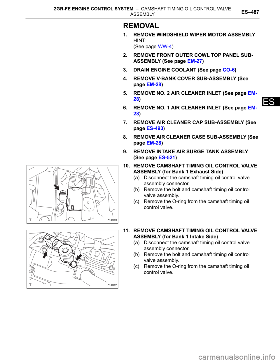
10. REMOVE CAMSHAFT TIMING OIL CONTROL VALVE
ASSEMBLY (for Bank 1 Exhaust Side)
(a) Disconnect the camshaft timing oil control valve
assembly connector.
(b) Remove the bolt and camshaft timing oil control
valve assembly.
(c) Remove the O-ring from the camshaft timing oil
control valve.
11. REMOVE CAMSHAFT TIMING OIL CONTROL VALVE
ASSEMBLY (for Bank 1 Intake Side)
(a) Disconnect the camshaft timing oil control valve
assembly connector.
(b) Remove the bolt and camshaft timing oil control
valve assembly.
(c) Remove the O-ring from the camshaft timing oil
control valve.
A135698
A135697