Page 2474 of 3000

BC–112BRAKE CONTROL – VEHICLE STABILITY CONTROL SYSTEM
BC
OK
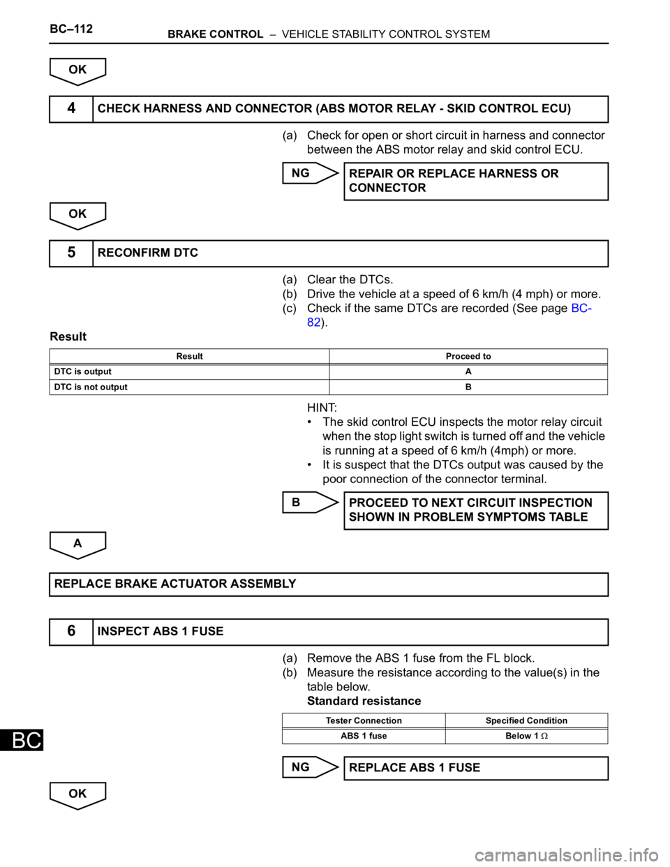
(a) Check for open or short circuit in harness and connector
between the ABS motor relay and skid control ECU.
NG
OK
(a) Clear the DTCs.
(b) Drive the vehicle at a speed of 6 km/h (4 mph) or more.
(c) Check if the same DTCs are recorded (See page BC-
82).
Result
HINT:
• The skid control ECU inspects the motor relay circuit
when the stop light switch is turned off and the vehicle
is running at a speed of 6 km/h (4mph) or more.
• It is suspect that the DTCs output was caused by the
poor connection of the connector terminal.
B
A
(a) Remove the ABS 1 fuse from the FL block.
(b) Measure the resistance according to the value(s) in the
table below.
Standard resistance
NG
OK
4CHECK HARNESS AND CONNECTOR (ABS MOTOR RELAY - SKID CONTROL ECU)
REPAIR OR REPLACE HARNESS OR
CONNECTOR
5RECONFIRM DTC
Result Proceed to
DTC is outputA
DTC is not outputB
PROCEED TO NEXT CIRCUIT INSPECTION
SHOWN IN PROBLEM SYMPTOMS TABLE
REPLACE BRAKE ACTUATOR ASSEMBLY
6INSPECT ABS 1 FUSE
Tester Connection Specified Condition
ABS 1 fuse Below 1
REPLACE ABS 1 FUSE
Page 2492 of 3000
BC–130BRAKE CONTROL – VEHICLE STABILITY CONTROL SYSTEM
BC
OK
(a) Disconnect the skid control ECU connector.
(b) Measure the resistance according to the value(s) in the
table below.
Standard resistance
NG
OK REPLACE BRAKE ACTUATOR ASSEMBLY
4INSPECT SKID CONTROL ECU (GND TERMINAL)
G024767E43
Tester Connection Specified Condition
S3-32 (GND1) - Body ground Below 1
S3-1 (GND2) - Body ground Below 1
REPAIR OR REPLACE HARNESS OR
CONNECTOR (GND CIRCUIT)
REPAIR OR REPLACE HARNESS OR CONNECTOR (IG1 CIRCUIT)
Page 2498 of 3000
BC–136BRAKE CONTROL – VEHICLE STABILITY CONTROL SYSTEM
BC
A
(a) Disconnect the stop light switch assembly connector.
(b) Measure the resistance according to the value(s) in the
table below.
Standard resistance
NG
OK
(a) Disconnect the stop light switch connector and skid
control ECU connector.
(b) Measure the resistance according to the value(s) in the
table below.
Standard resistance
NOTICE:
When replacing the brake actuator assembly,
perform zero point calibration (See page BC-70).
NG REPLACE BRAKE ACTUATOR ASSEMBLY
4INSPECT STOP LIGHT SWITCH
C146625E04
Tester connection Switch condition Specified condition
1 - 2 Switch pin free Below 1
1 - 2 Switch pin pushed in 10 k or higher
REPLACE STOP LIGHT SWITCH
5CHECK HARNESS AND CONNECTOR (STOP LIGHT SWITCH - SKID CONTROL ECU)
G026188E08
Tester Connection Specified Condition
S3-27 (STP1) - S12-1 (STP) Below 1
REPAIR OR REPLACE HARNESS OR
CONNECTOR
Page 2501 of 3000

BRAKE CONTROL – VEHICLE STABILITY CONTROL SYSTEMBC–139
BC
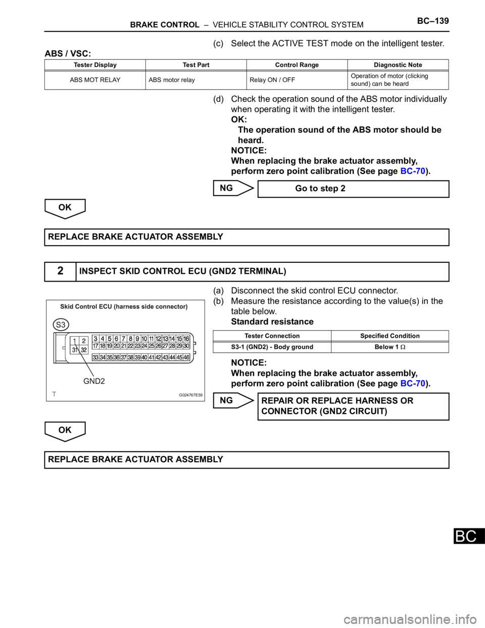
(c) Select the ACTIVE TEST mode on the intelligent tester.
ABS / VSC:
(d) Check the operation sound of the ABS motor individually
when operating it with the intelligent tester.
OK:
The operation sound of the ABS motor should be
heard.
NOTICE:
When replacing the brake actuator assembly,
perform zero point calibration (See page BC-70).
NG
OK
(a) Disconnect the skid control ECU connector.
(b) Measure the resistance according to the value(s) in the
table below.
Standard resistance
NOTICE:
When replacing the brake actuator assembly,
perform zero point calibration (See page BC-70).
NG
OK
Tester Display Test Part Control Range Diagnostic Note
ABS MOT RELAY ABS motor relay Relay ON / OFFOperation of motor (clicking
sound) can be heard
Go to step 2
REPLACE BRAKE ACTUATOR ASSEMBLY
2INSPECT SKID CONTROL ECU (GND2 TERMINAL)
G024767E59
Tester Connection Specified Condition
S3-1 (GND2) - Body ground Below 1
REPAIR OR REPLACE HARNESS OR
CONNECTOR (GND2 CIRCUIT)
REPLACE BRAKE ACTUATOR ASSEMBLY
Page 2505 of 3000
BRAKE CONTROL – VEHICLE STABILITY CONTROL SYSTEMBC–143
BC
DESCRIPTION
If any of the following is detected, the ABS warning light remains on.
• The skid control ECU connectors are disconnected from the skid control ECU.
• There is a malfunction in the skid control ECU internal circuit.
• There is an open in the harness between the combination meter and the skid control ECU.
HINT:
In some cases, the intelligent tester cannot be used when the skid control ECU is abnormal.
WIRING DIAGRAM
ABS Warning Light Remains ON
C160965E03
Page 2507 of 3000

BRAKE CONTROL – VEHICLE STABILITY CONTROL SYSTEMBC–145
BC
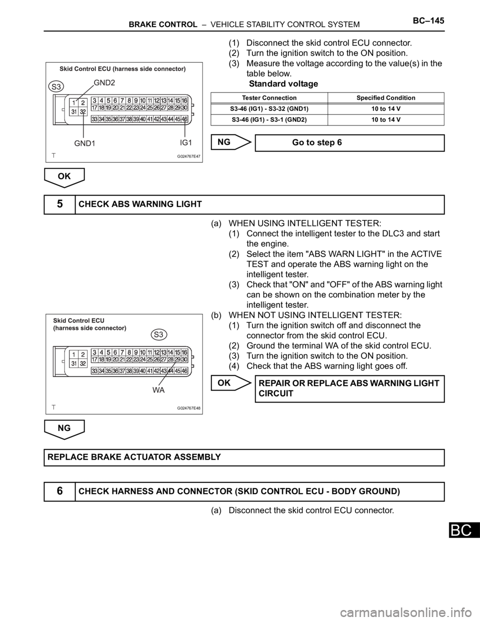
(1) Disconnect the skid control ECU connector.
(2) Turn the ignition switch to the ON position.
(3) Measure the voltage according to the value(s) in the
table below.
Standard voltage
NG
OK
(a) WHEN USING INTELLIGENT TESTER:
(1) Connect the intelligent tester to the DLC3 and start
the engine.
(2) Select the item "ABS WARN LIGHT" in the ACTIVE
TEST and operate the ABS warning light on the
intelligent tester.
(3) Check that "ON" and "OFF" of the ABS warning light
can be shown on the combination meter by the
intelligent tester.
(b) WHEN NOT USING INTELLIGENT TESTER:
(1) Turn the ignition switch off and disconnect the
connector from the skid control ECU.
(2) Ground the terminal WA of the skid control ECU.
(3) Turn the ignition switch to the ON position.
(4) Check that the ABS warning light goes off.
OK
NG
(a) Disconnect the skid control ECU connector.
G024767E47
Tester Connection Specified Condition
S3-46 (IG1) - S3-32 (GND1) 10 to 14 V
S3-46 (IG1) - S3-1 (GND2) 10 to 14 V
Go to step 6
5CHECK ABS WARNING LIGHT
G024767E48
REPAIR OR REPLACE ABS WARNING LIGHT
CIRCUIT
REPLACE BRAKE ACTUATOR ASSEMBLY
6CHECK HARNESS AND CONNECTOR (SKID CONTROL ECU - BODY GROUND)
Page 2509 of 3000
BRAKE CONTROL – VEHICLE STABILITY CONTROL SYSTEMBC–147
BC
WIRING DIAGRAM
Refer to ABS Warning Light Remains ON (See page BC-141).
INSPECTION PROCEDURE
(a) Disconnect the skid control ECU connector.
(b) Turn the ignition switch to the ON position.
(c) Check that the ABS warning light comes on.
OK:
ABS warning light comes on.
HINT:
If troubleshooting has been carried out according to the
PROBLEM SYMPTOMS TABLE, refer back to the table
and proceed to the next step (See page BC-79).
NG
OK
(a) Turn the ignition switch off.
(b) Disconnect the combination meter connector.
ABS Warning Light does not Come ON
1CHECK ABS WARNING LIGHT
Go to step 2
REPLACE BRAKE ACTUATOR ASSEMBLY
2CHECK HARNESS AND CONNECTOR (SKID CONTROL ECU - COMBINATION METER)
Page 2518 of 3000

BC–156BRAKE CONTROL – VEHICLE STABILITY CONTROL SYSTEM
BC
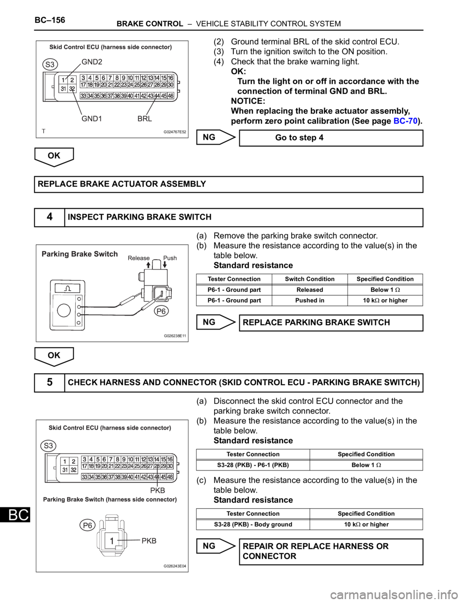
(2) Ground terminal BRL of the skid control ECU.
(3) Turn the ignition switch to the ON position.
(4) Check that the brake warning light.
OK:
Turn the light on or off in accordance with the
connection of terminal GND and BRL.
NOTICE:
When replacing the brake actuator assembly,
perform zero point calibration (See page BC-70).
NG
OK
(a) Remove the parking brake switch connector.
(b) Measure the resistance according to the value(s) in the
table below.
Standard resistance
NG
OK
(a) Disconnect the skid control ECU connector and the
parking brake switch connector.
(b) Measure the resistance according to the value(s) in the
table below.
Standard resistance
(c) Measure the resistance according to the value(s) in the
table below.
Standard resistance
NG
G024767E52 Go to step 4
REPLACE BRAKE ACTUATOR ASSEMBLY
4INSPECT PARKING BRAKE SWITCH
G026238E11
Tester Connection Switch Condition Specified Condition
P6-1 - Ground part Released Below 1
P6-1 - Ground part Pushed in 10 k or higher
REPLACE PARKING BRAKE SWITCH
5CHECK HARNESS AND CONNECTOR (SKID CONTROL ECU - PARKING BRAKE SWITCH)
G026243E04
Tester Connection Specified Condition
S3-28 (PKB) - P6-1 (PKB) Below 1
Tester Connection Specified Condition
S3-28 (PKB) - Body ground 10 k
or higher
REPAIR OR REPLACE HARNESS OR
CONNECTOR