Page 2420 of 3000
BRAKE CONTROL – ANTI-LOCK BRAKE SYSTEMBC–59
BC
(b) Measure the resistance according to the value(s) in the
table below.
Standard resistance
NG
OK
(a) Turn the ignition switch off.
(b) Disconnect the combination meter connector.
C119429E03
Tester Connection Specified Condition
C10-13 - B1-1 Below 1
C10-13 - Body ground 10 k or higher
B1-2 - Body ground Below 1
REPAIR OR REPLACE HARNESS OR
CONNECTOR (BRAKE FLUID LEVEL
WARNING SWITCH CIRCUIT)
10CHECK HARNESS AND CONNECTOR (BETWEEN SKID CONTROL ECU AND
COMBINATION METER ASSEMBLY)
Page 2422 of 3000
BRAKE CONTROL – ANTI-LOCK BRAKE SYSTEMBC–61
BC
WIRING DIAGRAM
See page BC-52.
INSPECTION PROCEDURE
(a) Disconnect the skid control ECU connector.
(b) Turn the ignition switch to the on position.
(c) Check that the BRAKE warning light comes on.
OK:
BRAKE warning light comes on.
HINT:
If troubleshooting has been carried out according to the
PROBLEM SYMPTOMS TABLE, refer back to the table and
proceed to the next step before replacing the part (See page
BC-7).
NG
OK
(a) Turn the ignition switch off.
(b) Disconnect the combination meter connector.
Brake Warning Light does not Come ON
1INSPECT BRAKE WARNING LIGHT
Go to step 2
REPLACE BRAKE ACTUATOR ASSEMBLY
2CHECK HARNESS AND CONNECTOR (BETWEEN SKID CONTROL ECU AND
COMBINATION METER ASSEMBLY)
Page 2425 of 3000
BC–64BRAKE CONTROL – ANTI-LOCK BRAKE SYSTEM
BC
(a) Turn the ignition switch off.
(b) Disconnect the skid control ECU connector.
(c) Measure the resistance according to the value(s) in the
table below.
Standard resistance
NG
OK
(a) Turn the ignition switch off.
(b) Measure the resistance according to the value(s) in the
table below.
Standard resistance
NG
OK
2CHECK HARNESS AND CONNECTOR (BETWEEN SKID CONTROL ECU AND TC of DLC3)
C127347E05
Tester Connection Specified Condition
S3-8 (TC) - D1-13 (TC) Below 1
S3-8 (TC) - Body ground 10 k or higher
REPAIR OR REPLACE HARNESS OR
CONNECTOR
REPLACE BRAKE ACTUATOR ASSEMBLY
3CHECK HARNESS AND CONNECTOR (BETWEEN CG of DLC3 AND BODY GROUND)
E106867E27
Tester Connection Specified Condition
D1-4 (CG) - Body ground Below 1
REPAIR OR REPLACE HARNESS OR
CONNECTOR
Page 2426 of 3000
BRAKE CONTROL – ANTI-LOCK BRAKE SYSTEMBC–65
BC
(a) Disconnect the skid control ECU connector.
(b) Measure the resistance according to the value(s) in the
table below.
Standard resistance
NG
OK
4CHECK HARNESS AND CONNECTOR (BETWEEN SKID CONTROL ECU AND TC of DLC3)
C127347E06
Tester Connection Specified Condition
S3-8 (TC) - D1-13 (TC) Below 1
S3-8 (TC) - Body ground 10 k or higher
REPAIR OR REPLACE HARNESS OR
CONNECTOR
REPLACE BRAKE ACTUATOR ASSEMBLY
Page 2428 of 3000
BRAKE CONTROL – ANTI-LOCK BRAKE SYSTEMBC–67
BC
INSPECTION PROCEDURE
(a) Turn the ignition switch off.
(b) Disconnect the skid control ECU connector.
(c) Measure the resistance according to the value(s) in the
table below.
Standard resistance
NG
OK
(a) Measure the resistance according to the value(s) in the
table below.
Standard resistance
NG
OK
1CHECK HARNESS AND CONNECTOR (BETWEEN SKID CONTROL ECU AND TS of DLC3)
C127347E07
Tester Connection Specified Condition
S3-10 (TS) - D1-12 (TS) Below 1
REPAIR OR REPLACE HARNESS OR
CONNECTOR
2CHECK HARNESS AND CONNECTOR (BETWEEN CG of DLC3 AND BODY GROUND)
E106867E28
Tester Connection Specified Condition
D1-4 (CG) - Body ground Below 1
REPAIR OR REPLACE HARNESS OR
CONNECTOR
Page 2437 of 3000

BRAKE CONTROL – VEHICLE STABILITY CONTROL SYSTEMBC–73
BC
TEST MODE PROCEDURE
1. WARNING LIGHT AND INDICATOR LIGHT BULB
CHECK
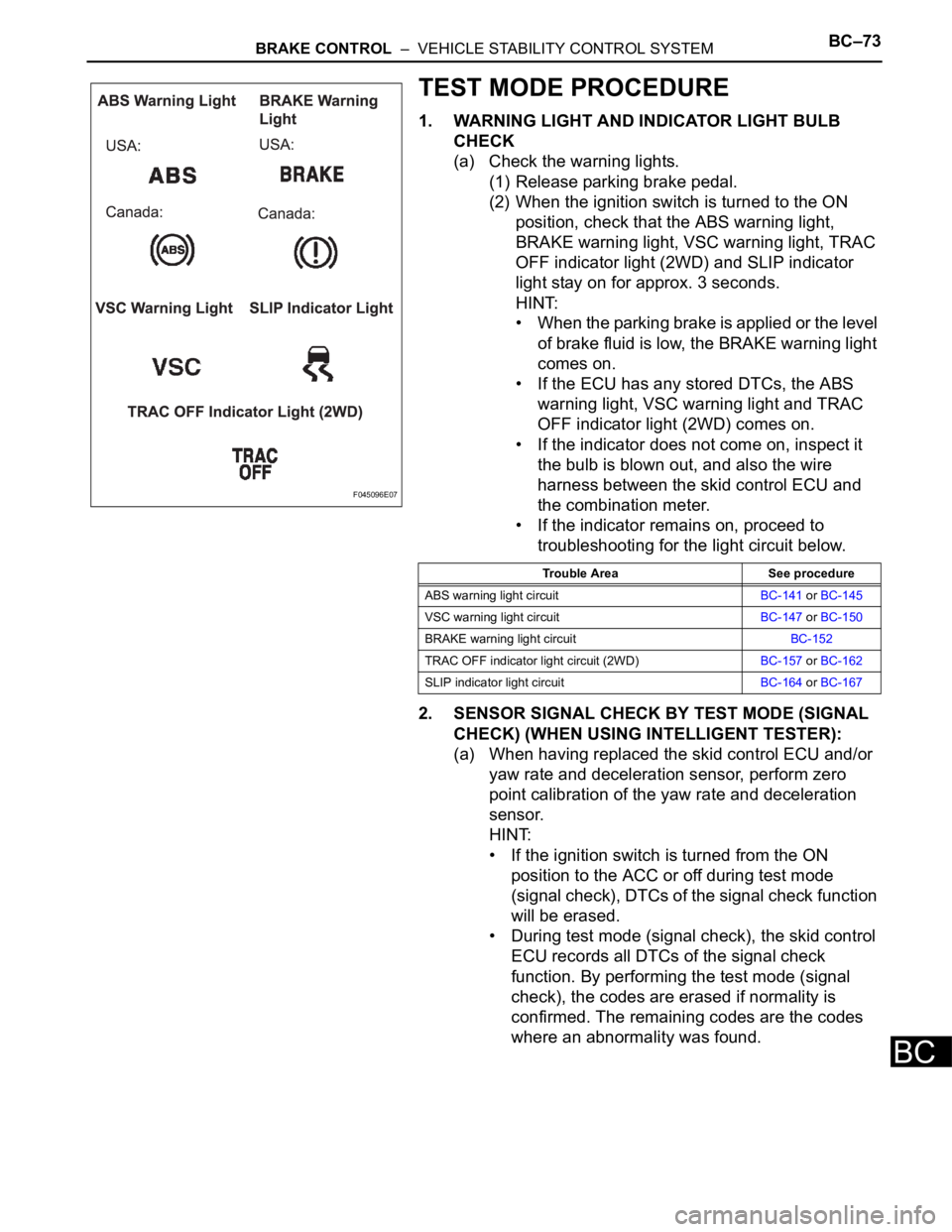
(a) Check the warning lights.
(1) Release parking brake pedal.
(2) When the ignition switch is turned to the ON
position, check that the ABS warning light,
BRAKE warning light, VSC warning light, TRAC
OFF indicator light (2WD) and SLIP indicator
light stay on for approx. 3 seconds.
HINT:
• When the parking brake is applied or the level
of brake fluid is low, the BRAKE warning light
comes on.
• If the ECU has any stored DTCs, the ABS
warning light, VSC warning light and TRAC
OFF indicator light (2WD) comes on.
• If the indicator does not come on, inspect it
the bulb is blown out, and also the wire
harness between the skid control ECU and
the combination meter.
• If the indicator remains on, proceed to
troubleshooting for the light circuit below.
2. SENSOR SIGNAL CHECK BY TEST MODE (SIGNAL
CHECK) (WHEN USING INTELLIGENT TESTER):
(a) When having replaced the skid control ECU and/or
yaw rate and deceleration sensor, perform zero
point calibration of the yaw rate and deceleration
sensor.
HINT:
• If the ignition switch is turned from the ON
position to the ACC or off during test mode
(signal check), DTCs of the signal check function
will be erased.
• During test mode (signal check), the skid control
ECU records all DTCs of the signal check
function. By performing the test mode (signal
check), the codes are erased if normality is
confirmed. The remaining codes are the codes
where an abnormality was found.
F045096E07
Trouble Area See procedure
ABS warning light circuitBC-141 or BC-145
VSC warning light circuitBC-147 or BC-150
BRAKE warning light circuitBC-152
TRAC OFF indicator light circuit (2WD)BC-157 or BC-162
SLIP indicator light circuitBC-164 or BC-167
Page 2459 of 3000

BRAKE CONTROL – VEHICLE STABILITY CONTROL SYSTEMBC–97
BC
RH
NOTICE:
Check the speed sensor signal after replacement
(See page BC-72).
NG
OK
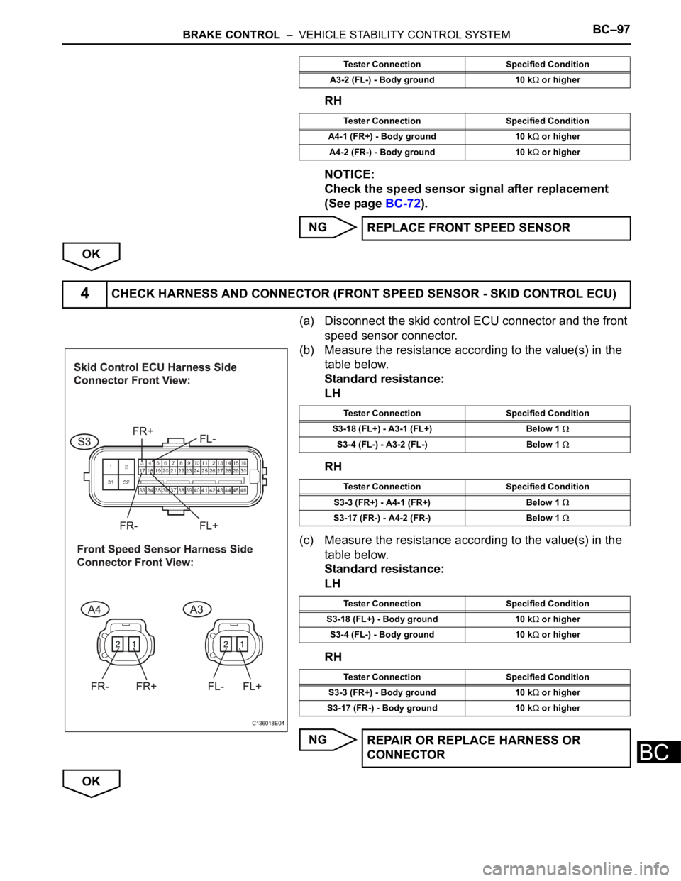
(a) Disconnect the skid control ECU connector and the front
speed sensor connector.
(b) Measure the resistance according to the value(s) in the
table below.
Standard resistance:
LH
RH
(c) Measure the resistance according to the value(s) in the
table below.
Standard resistance:
LH
RH
NG
OK
A3-2 (FL-) - Body ground 10 k or higher
Tester Connection Specified Condition
A4-1 (FR+) - Body ground 10 k
or higher
A4-2 (FR-) - Body ground 10 k
or higher
REPLACE FRONT SPEED SENSOR
Tester Connection Specified Condition
4CHECK HARNESS AND CONNECTOR (FRONT SPEED SENSOR - SKID CONTROL ECU)
C136018E04
Tester Connection Specified Condition
S3-18 (FL+) - A3-1 (FL+) Below 1
S3-4 (FL-) - A3-2 (FL-) Below 1
Tester Connection Specified Condition
S3-3 (FR+) - A4-1 (FR+) Below 1
S3-17 (FR-) - A4-2 (FR-) Below 1
Tester Connection Specified Condition
S3-18 (FL+) - Body ground 10 k
or higher
S3-4 (FL-) - Body ground 10 k
or higher
Tester Connection Specified Condition
S3-3 (FR+) - Body ground 10 k
or higher
S3-17 (FR-) - Body ground 10 k
or higher
REPAIR OR REPLACE HARNESS OR
CONNECTOR
Page 2465 of 3000

BRAKE CONTROL – VEHICLE STABILITY CONTROL SYSTEMBC–103
BC
Standard resistance:
LH
RH
NOTICE:
Check the speed sensor signal after the
replacement. (See page BC-72)
NG
OK
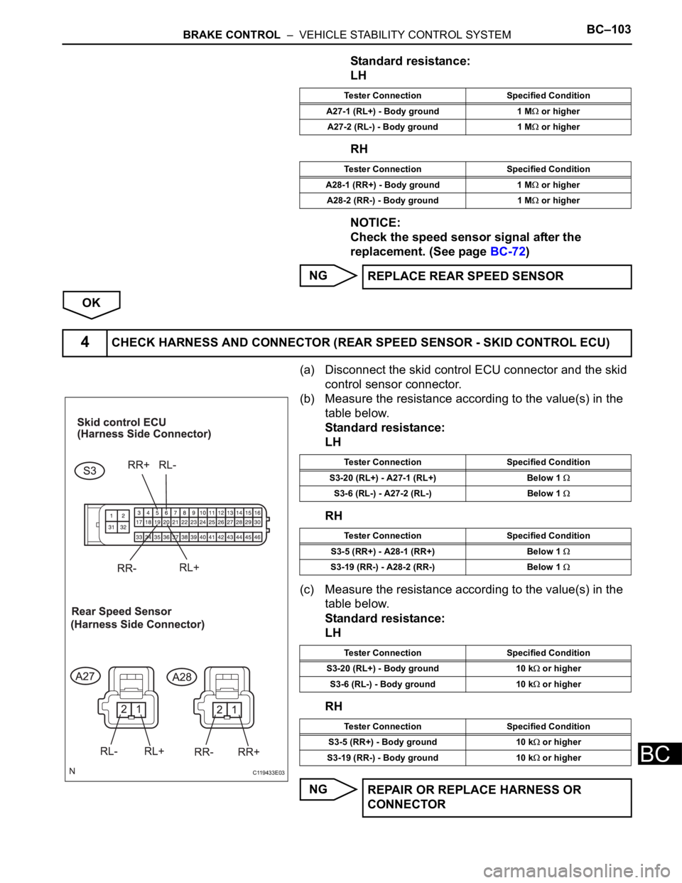
(a) Disconnect the skid control ECU connector and the skid
control sensor connector.
(b) Measure the resistance according to the value(s) in the
table below.
Standard resistance:
LH
RH
(c) Measure the resistance according to the value(s) in the
table below.
Standard resistance:
LH
RH
NG
Tester Connection Specified Condition
A27-1 (RL+) - Body ground 1 M
or higher
A27-2 (RL-) - Body ground 1 M
or higher
Tester Connection Specified Condition
A28-1 (RR+) - Body ground 1 M
or higher
A28-2 (RR-) - Body ground 1 M
or higher
REPLACE REAR SPEED SENSOR
4CHECK HARNESS AND CONNECTOR (REAR SPEED SENSOR - SKID CONTROL ECU)
C119433E03
Tester Connection Specified Condition
S3-20 (RL+) - A27-1 (RL+) Below 1
S3-6 (RL-) - A27-2 (RL-) Below 1
Tester Connection Specified Condition
S3-5 (RR+) - A28-1 (RR+) Below 1
S3-19 (RR-) - A28-2 (RR-) Below 1
Tester Connection Specified Condition
S3-20 (RL+) - Body ground 10 k
or higher
S3-6 (RL-) - Body ground 10 k
or higher
Tester Connection Specified Condition
S3-5 (RR+) - Body ground 10 k
or higher
S3-19 (RR-) - Body ground 10 k
or higher
REPAIR OR REPLACE HARNESS OR
CONNECTOR