2007 TOYOTA SIENNA ecu harness
[x] Cancel search: ecu harnessPage 2325 of 3000
TIRE AND WHEEL – TIRE PRESSURE WARNING SYSTEMTW–83
TW
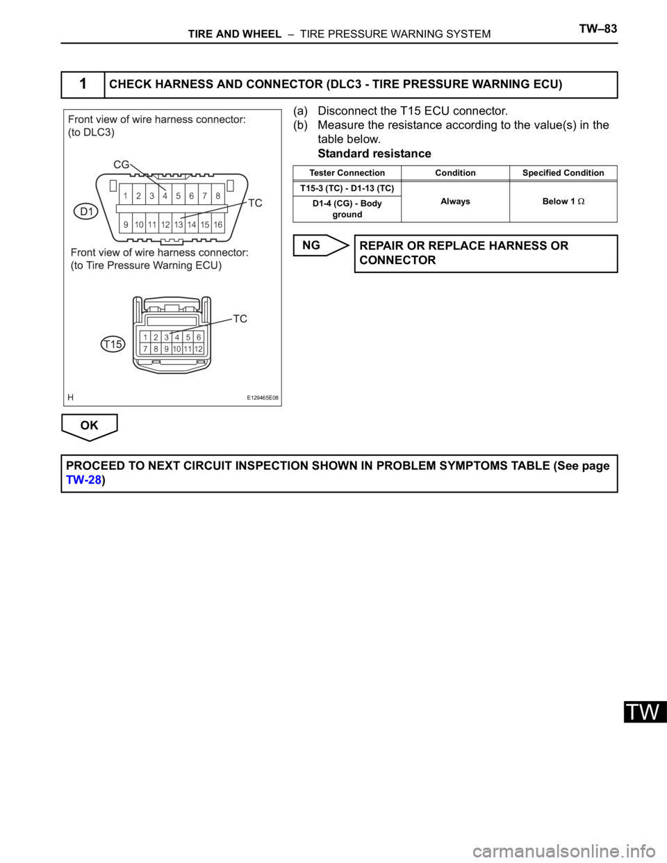
(a) Disconnect the T15 ECU connector.
(b) Measure the resistance according to the value(s) in the
table below.
Standard resistance
NG
OK
1CHECK HARNESS AND CONNECTOR (DLC3 - TIRE PRESSURE WARNING ECU)
E129465E08
Tester Connection Condition Specified Condition
T15-3 (TC) - D1-13 (TC)
Always Below 1
D1-4 (CG) - Body
ground
REPAIR OR REPLACE HARNESS OR
CONNECTOR
PROCEED TO NEXT CIRCUIT INSPECTION SHOWN IN PROBLEM SYMPTOMS TABLE (See page
TW-28)
Page 2342 of 3000
TW–30TIRE AND WHEEL – TIRE PRESSURE WARNING SYSTEM
TW
(2) Check the tire pressure warning indicator light.
(i) Result
HINT:
After the signal check is completed, check for a
signal check DTC to confirm the system status.
(j) End of SIGNAL CHECK
After completing the test mode (SIGNAL CHECK),
turn the ignition switch off and disconnect the tester.
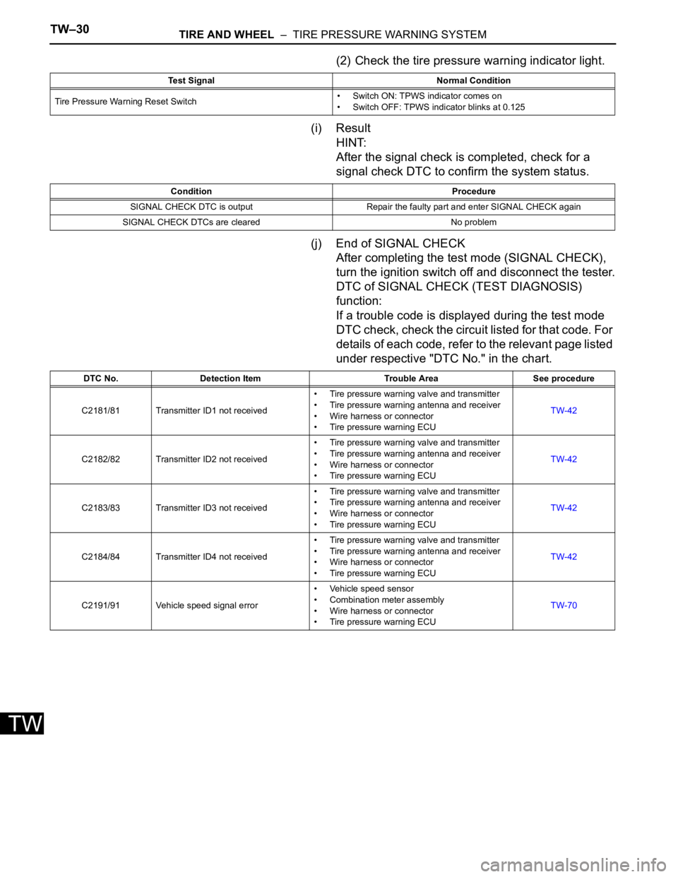
DTC of SIGNAL CHECK (TEST DIAGNOSIS)
function:
If a trouble code is displayed during the test mode
DTC check, check the circuit listed for that code. For
details of each code, refer to the relevant page listed
under respective "DTC No." in the chart.
Test Signal Normal Condition
Tire Pressure Warning Reset Switch• Switch ON: TPWS indicator comes on
• Switch OFF: TPWS indicator blinks at 0.125
Condition Procedure
SIGNAL CHECK DTC is output Repair the faulty part and enter SIGNAL CHECK again
SIGNAL CHECK DTCs are cleared No problem
DTC No. Detection Item Trouble Area See procedure
C2181/81 Transmitter ID1 not received• Tire pressure warning valve and transmitter
• Tire pressure warning antenna and receiver
• Wire harness or connector
• Tire pressure warning ECUTW-42
C2182/82 Transmitter ID2 not received• Tire pressure warning valve and transmitter
• Tire pressure warning antenna and receiver
• Wire harness or connector
• Tire pressure warning ECUTW-42
C2183/83 Transmitter ID3 not received• Tire pressure warning valve and transmitter
• Tire pressure warning antenna and receiver
• Wire harness or connector
• Tire pressure warning ECUTW-42
C2184/84 Transmitter ID4 not received• Tire pressure warning valve and transmitter
• Tire pressure warning antenna and receiver
• Wire harness or connector
• Tire pressure warning ECUTW-42
C2191/91 Vehicle speed signal error• Vehicle speed sensor
• Combination meter assembly
• Wire harness or connector
• Tire pressure warning ECUTW-70
Page 2352 of 3000
TW–34TIRE AND WHEEL – TIRE PRESSURE WARNING SYSTEM
TW
DIAGNOSIS SYSTEM
1. CHECK BATTERY VOLTAGE
Standard voltage:
11 to 14 V
If the voltage is below 11 V, recharge the battery before
proceeding.
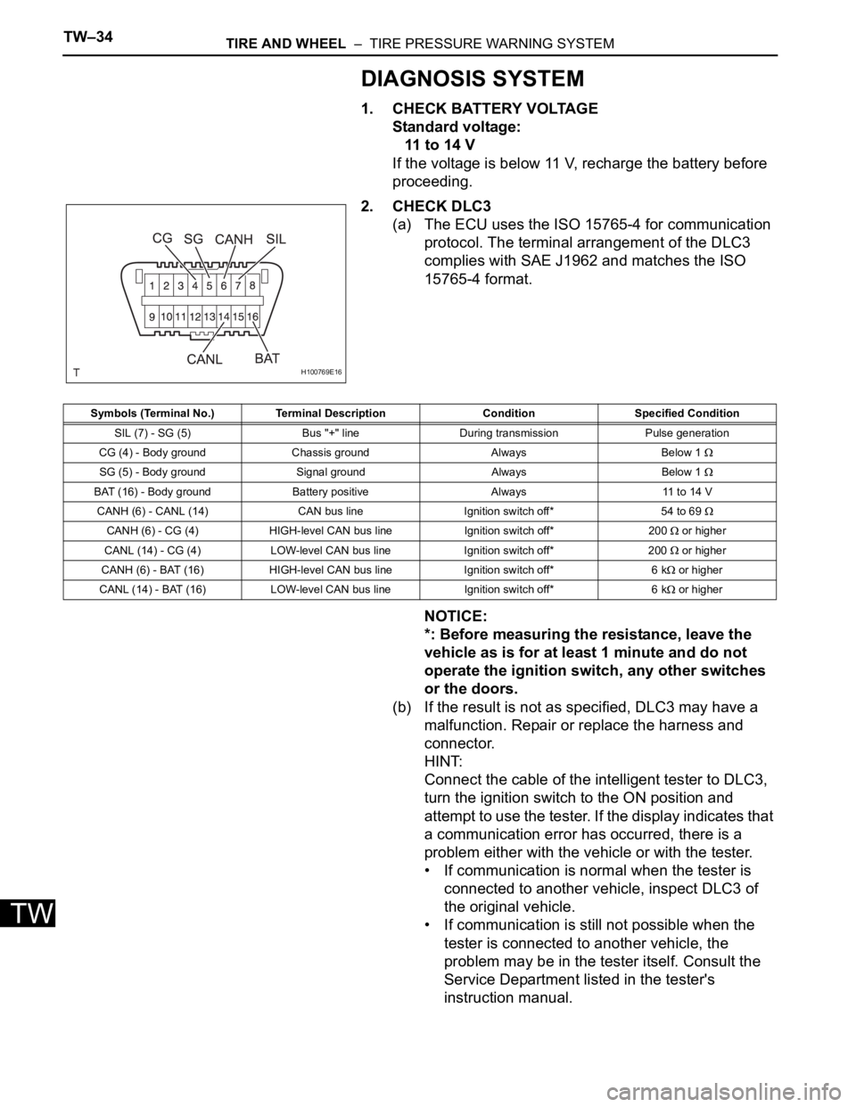
2. CHECK DLC3
(a) The ECU uses the ISO 15765-4 for communication
protocol. The terminal arrangement of the DLC3
complies with SAE J1962 and matches the ISO
15765-4 format.
NOTICE:
*: Before measuring the resistance, leave the
vehicle as is for at least 1 minute and do not
operate the ignition switch, any other switches
or the doors.
(b) If the result is not as specified, DLC3 may have a
malfunction. Repair or replace the harness and
connector.
HINT:
Connect the cable of the intelligent tester to DLC3,
turn the ignition switch to the ON position and
attempt to use the tester. If the display indicates that
a communication error has occurred, there is a
problem either with the vehicle or with the tester.
• If communication is normal when the tester is
connected to another vehicle, inspect DLC3 of
the original vehicle.
• If communication is still not possible when the
tester is connected to another vehicle, the
problem may be in the tester itself. Consult the
Service Department listed in the tester's
instruction manual.
H100769E16
Symbols (Terminal No.) Terminal Description Condition Specified Condition
SIL (7) - SG (5) Bus "+" line During transmission Pulse generation
CG (4) - Body ground Chassis ground Always Below 1
SG (5) - Body ground Signal ground Always Below 1
BAT (16) - Body ground Battery positive Always 11 to 14 V
CANH (6) - CANL (14) CAN bus line Ignition switch off* 54 to 69
CANH (6) - CG (4) HIGH-level CAN bus line Ignition switch off* 200 or higher
CANL (14) - CG (4) LOW-level CAN bus line Ignition switch off* 200
or higher
CANH (6) - BAT (16) HIGH-level CAN bus line Ignition switch off* 6 k
or higher
CANL (14) - BAT (16) LOW-level CAN bus line Ignition switch off* 6 k
or higher
Page 2358 of 3000
TW–40TIRE AND WHEEL – TIRE PRESSURE WARNING SYSTEM
TW
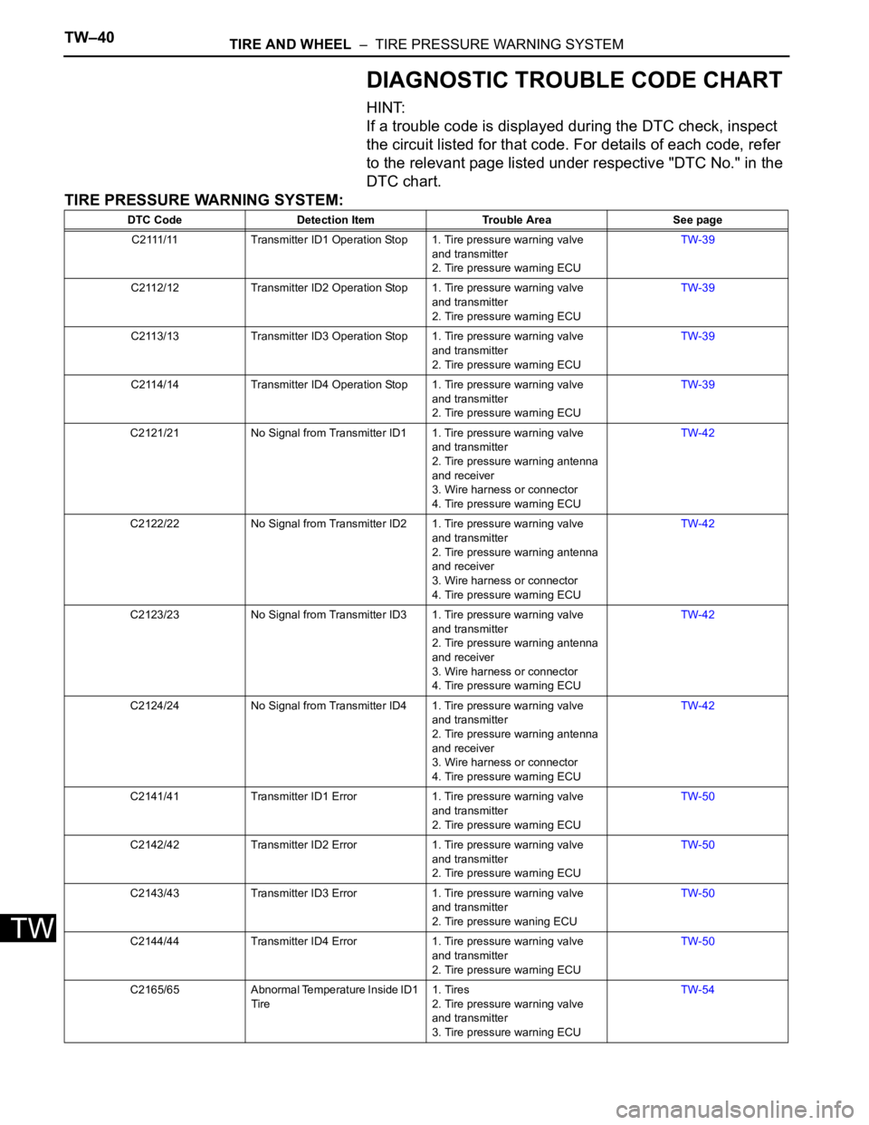
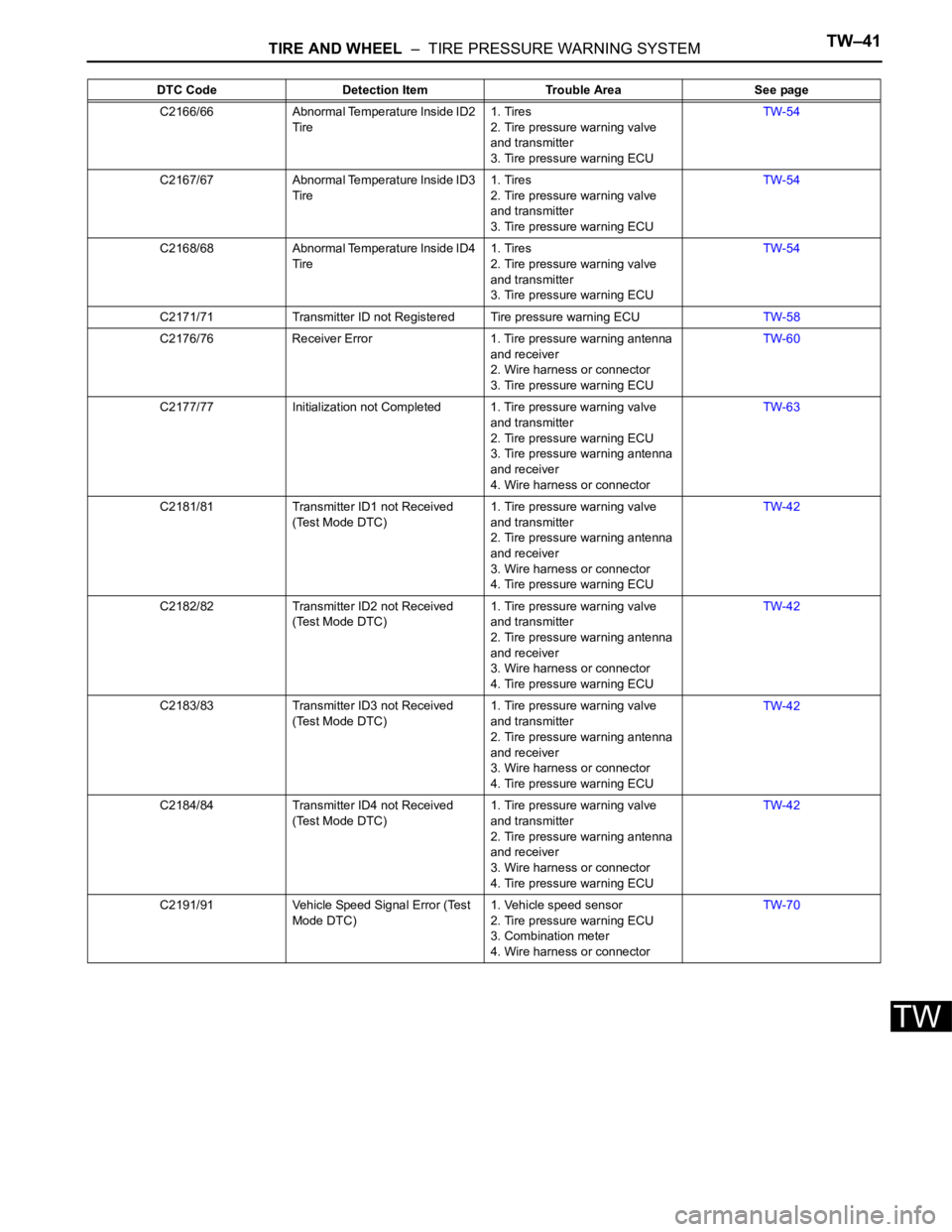
DIAGNOSTIC TROUBLE CODE CHART
HINT:
If a trouble code is displayed during the DTC check, inspect
the circuit listed for that code. For details of each code, refer
to the relevant page listed under respective "DTC No." in the
DTC chart.
TIRE PRESSURE WARNING SYSTEM:
DTC Code Detection Item Trouble Area See page
C2111/11 Transmitter ID1 Operation Stop 1. Tire pressure warning valve
and transmitter
2. Tire pressure warning ECUTW-39
C2112/12 Transmitter ID2 Operation Stop 1. Tire pressure warning valve
and transmitter
2. Tire pressure warning ECUTW-39
C2113/13 Transmitter ID3 Operation Stop 1. Tire pressure warning valve
and transmitter
2. Tire pressure warning ECUTW-39
C2114/14 Transmitter ID4 Operation Stop 1. Tire pressure warning valve
and transmitter
2. Tire pressure warning ECUTW-39
C2121/21 No Signal from Transmitter ID1 1. Tire pressure warning valve
and transmitter
2. Tire pressure warning antenna
and receiver
3. Wire harness or connector
4. Tire pressure warning ECUTW-42
C2122/22 No Signal from Transmitter ID2 1. Tire pressure warning valve
and transmitter
2. Tire pressure warning antenna
and receiver
3. Wire harness or connector
4. Tire pressure warning ECUTW-42
C2123/23 No Signal from Transmitter ID3 1. Tire pressure warning valve
and transmitter
2. Tire pressure warning antenna
and receiver
3. Wire harness or connector
4. Tire pressure warning ECUTW-42
C2124/24 No Signal from Transmitter ID4 1. Tire pressure warning valve
and transmitter
2. Tire pressure warning antenna
and receiver
3. Wire harness or connector
4. Tire pressure warning ECUTW-42
C2141/41 Transmitter ID1 Error 1. Tire pressure warning valve
and transmitter
2. Tire pressure warning ECUTW-50
C2142/42 Transmitter ID2 Error 1. Tire pressure warning valve
and transmitter
2. Tire pressure warning ECUTW-50
C2143/43 Transmitter ID3 Error 1. Tire pressure warning valve
and transmitter
2. Tire pressure waning ECUTW-50
C2144/44 Transmitter ID4 Error 1. Tire pressure warning valve
and transmitter
2. Tire pressure warning ECUTW-50
C2165/65 Abnormal Temperature Inside ID1
Tire1. Tires
2. Tire pressure warning valve
and transmitter
3. Tire pressure warning ECUTW-54
Page 2359 of 3000
TIRE AND WHEEL – TIRE PRESSURE WARNING SYSTEMTW–41
TW
C2166/66 Abnormal Temperature Inside ID2
Tire1. Tires
2. Tire pressure warning valve
and transmitter
3. Tire pressure warning ECUTW-54
C2167/67 Abnormal Temperature Inside ID3
Tire1. Tires
2. Tire pressure warning valve
and transmitter
3. Tire pressure warning ECUTW-54
C2168/68 Abnormal Temperature Inside ID4
Tire1. Tires
2. Tire pressure warning valve
and transmitter
3. Tire pressure warning ECUTW-54
C2171/71 Transmitter ID not Registered Tire pressure warning ECUTW-58
C2176/76 Receiver Error 1. Tire pressure warning antenna
and receiver
2. Wire harness or connector
3. Tire pressure warning ECUTW-60
C2177/77 Initialization not Completed 1. Tire pressure warning valve
and transmitter
2. Tire pressure warning ECU
3. Tire pressure warning antenna
and receiver
4. Wire harness or connectorTW-63
C2181/81 Transmitter ID1 not Received
(Test Mode DTC)1. Tire pressure warning valve
and transmitter
2. Tire pressure warning antenna
and receiver
3. Wire harness or connector
4. Tire pressure warning ECUTW-42
C2182/82 Transmitter ID2 not Received
(Test Mode DTC)1. Tire pressure warning valve
and transmitter
2. Tire pressure warning antenna
and receiver
3. Wire harness or connector
4. Tire pressure warning ECUTW-42
C2183/83 Transmitter ID3 not Received
(Test Mode DTC)1. Tire pressure warning valve
and transmitter
2. Tire pressure warning antenna
and receiver
3. Wire harness or connector
4. Tire pressure warning ECUTW-42
C2184/84 Transmitter ID4 not Received
(Test Mode DTC)1. Tire pressure warning valve
and transmitter
2. Tire pressure warning antenna
and receiver
3. Wire harness or connector
4. Tire pressure warning ECUTW-42
C2191/91 Vehicle Speed Signal Error (Test
Mode DTC)1. Vehicle speed sensor
2. Tire pressure warning ECU
3. Combination meter
4. Wire harness or connectorTW-70 DTC Code Detection Item Trouble Area See page
Page 2377 of 3000
BRAKE CONTROL – ANTI-LOCK BRAKE SYSTEMBC–29
BC
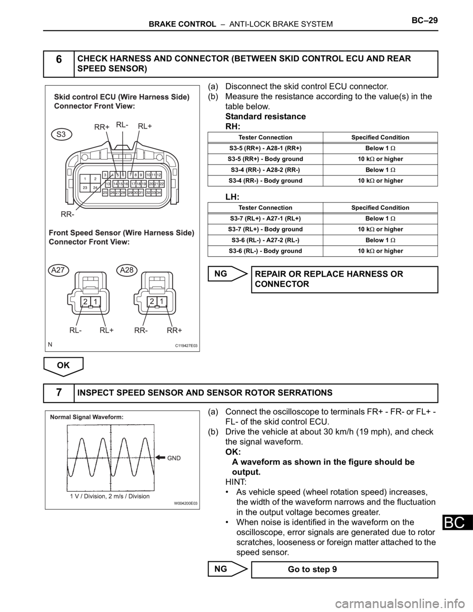
(a) Disconnect the skid control ECU connector.
(b) Measure the resistance according to the value(s) in the
table below.
Standard resistance
RH:
LH:
NG
OK
(a) Connect the oscilloscope to terminals FR+ - FR- or FL+ -
FL- of the skid control ECU.
(b) Drive the vehicle at about 30 km/h (19 mph), and check
the signal waveform.
OK:
A waveform as shown in the figure should be
output.
HINT:
• As vehicle speed (wheel rotation speed) increases,
the width of the waveform narrows and the fluctuation
in the output voltage becomes greater.
• When noise is identified in the waveform on the
oscilloscope, error signals are generated due to rotor
scratches, looseness or foreign matter attached to the
speed sensor.
NG
6CHECK HARNESS AND CONNECTOR (BETWEEN SKID CONTROL ECU AND REAR
SPEED SENSOR)
C119427E03
Tester Connection Specified Condition
S3-5 (RR+) - A28-1 (RR+) Below 1
S3-5 (RR+) - Body ground 10 k or higher
S3-4 (RR-) - A28-2 (RR-) Below 1
S3-4 (RR-) - Body ground 10 k or higher
Tester Connection Specified Condition
S3-7 (RL+) - A27-1 (RL+) Below 1
S3-7 (RL+) - Body ground 10 k or higher
S3-6 (RL-) - A27-2 (RL-) Below 1
S3-6 (RL-) - Body ground 10 k or higher
REPAIR OR REPLACE HARNESS OR
CONNECTOR
7INSPECT SPEED SENSOR AND SENSOR ROTOR SERRATIONS
W004200E03
Go to step 9
Page 2390 of 3000

BRAKE CONTROL – ANTI-LOCK BRAKE SYSTEMBC–23
BC
(a) Disconnect the skid control sensor wire.
(b) Measure the resistance according to the value(s) in the
table below.
Standard resistance
RH:
LH:
NG
OK
(a) Connect the oscilloscope to terminals FR+ - FR- or FL+ -
FL- of the skid control ECU.
(b) Drive the vehicle at about 30 km/h(19 mph), and check
the signal waveform.
OK:
A waveform as shown in the figure should be
output.
HINT:
• As vehicle speed (wheel rotation speed) increases,
the width of the waveform narrows and the fluctuation
in the output voltage becomes greater.
• When noise is identified in the waveform on the
oscilloscope, error signals are generated due to rotor
scratches, looseness or foreign matter attached to the
speed sensor.
NG
6CHECK HARNESS AND CONNECTOR (BETWEEN SKID CONTROL ECU AND FRONT
SPEED SENSOR)
C161174E02
Tester Connection Specified Condition
S3-27 (FR+) - A4-1 (FR+) Below 1
S3-27 (FR+) - Body ground 10 k or higher
S3-28 (FR-) - A4-2 (FR-) Below 1
S3-28 (FR-) - Body ground 10 k or higher
Tester Connection Specified Condition
S3-13 (FL+) - A3-1 (FL+) Below 1
S3-13 (FL+) - Body ground 10 k or higher
S3-26 (FL-) - A3-2 (FL-) Below 1
S3-26 (FL-) - Body ground 10 k or higher
REPAIR OR REPLACE HARNESS OR
CONNECTOR
7INSPECT SPEED SENSOR AND SENSOR ROTOR SERRATIONS
W004200E03
Go to step 9
Page 2393 of 3000
BC–32BRAKE CONTROL – ANTI-LOCK BRAKE SYSTEM
BC
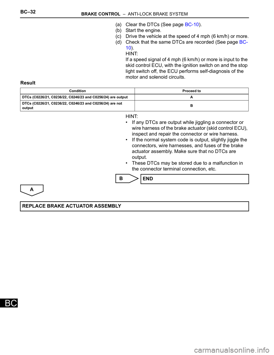
(a) Clear the DTCs (See page BC-10).
(b) Start the engine.
(c) Drive the vehicle at the speed of 4 mph (6 km/h) or more.
(d) Check that the same DTCs are recorded (See page BC-
10).
HINT:
If a speed signal of 4 mph (6 km/h) or more is input to the
skid control ECU, with the ignition switch on and the stop
light switch off, the ECU performs self-diagnosis of the
motor and solenoid circuits.
Result
HINT:
• If any DTCs are output while jiggling a connector or
wire harness of the brake actuator (skid control ECU),
inspect and repair the connector or wire harness.
• If the normal system code is output, slightly jiggle the
connectors, wire harnesses, and fuses of the brake
actuator assembly. Make sure that no DTCs are
output.
• These DTCs may be stored due to a malfunction in
the connector terminal connection, etc.
B
A
Condition Proceed to
DTCs (C0226/21, C0236/22, C0246/23 and C0256/24) are output A
DTCs (C0226/21, C0236/22, C0246/23 and C0256/24) are not
outputB
END
REPLACE BRAKE ACTUATOR ASSEMBLY