2007 TOYOTA SIENNA ecu harness
[x] Cancel search: ecu harnessPage 1717 of 3000

U151F AUTOMATIC TRANSAXLE – AUTOMATIC TRANSAXLE SYSTEMAX–45
AX
DESCRIPTION
The park/neutral position switch detects the shift lever position and sends signals to the ECM.
MONITOR DESCRIPTION
These DTCs indicate a problem with the park/neutral position switch and the wire harness in the park/
neutral position switch circuit.
The park/neutral position switch detects the shift lever position and sends a signal to the ECM.
For security, the park/neutral position switch detects the shift lever position so that engine can be started
only when the shift lever is in the P or N position
The park/neutral position switch sends a signal to the ECM according to the shift position (P, R, N or D).
The ECM determines that there is a problem with the switch or related parts if in receives more than 1
position signal simultaneously. The ECM will turn on the MIL and store the DTC.
MONITOR STRATEGY
DTC P0705Transmission Range Sensor Circuit Malfunc-
tion (PRNDL Input)
DTC No. DTC Detection Condition Trouble Area
P0705(A) Any 2 or more signals of the following are ON
simultaneously (2-trip detection logic)
• P input signal is ON.
• N input signal is ON.
• R input signal is ON.
• D input signal is ON.
• 3 input signal is ON.
• 2 input signal is ON.
(B) Any 2 or more signals of the following are ON
simultaneously (2-trip detection logic)
• NSW (STAR) input signal is ON.
• R input signal is ON.
• D input signal is ON.
• 3 input signal is ON.
• 2 input signal is ON.
(C) All switches are OFF simultaneously for
NSW(STAR), P, R, N, D, 3, 2 positions (2-trip detection
logic).
(D) Both 1 and 2 conditions are met (2-trip detection
logic)
1. One of the following conditions are met
(a) NSW (STAR) input signal is ON.
(b) P input signal is ON.
(c) N input signal is ON.
(d) R input signal is ON.
2. One of the following conditions are met
(a) 4 input signal is ON.
(b) L input signal is ON.• Short in park/neutral position switch circuit
• Park/neutral position switch
•ECM
Related DTCs P0705: Park/neutral position switch/Verify switch input
Required sensors/Components Park/neutral position switch
Frequency of operation Continuous
DurationCondition (A), (B), (D)
2 sec.
Condition (C)
60 sec.
MIL operation 2 driving cycles
Sequence of operation None
Page 1743 of 3000

U151F AUTOMATIC TRANSAXLE – AUTOMATIC TRANSAXLE SYSTEMAX–71
AX
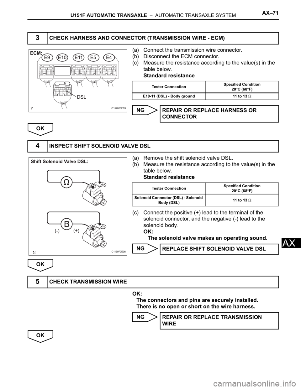
(a) Connect the transmission wire connector.
(b) Disconnect the ECM connector.
(c) Measure the resistance according to the value(s) in the
table below.
Standard resistance
NG
OK
(a) Remove the shift solenoid valve DSL.
(b) Measure the resistance according to the value(s) in the
table below.
Standard resistance
(c) Connect the positive (+) lead to the terminal of the
solenoid connector, and the negative (-) lead to the
solenoid body.
OK:
The solenoid valve makes an operating sound.
NG
OK
OK:
The connectors and pins are securely installed.
There is no open or short on the wire harness.
NG
OK
3CHECK HARNESS AND CONNECTOR (TRANSMISSION WIRE - ECM)
C152056E03
Tester ConnectionSpecified Condition
20C (68F)
E10-11 (DSL) - Body ground 11 to 13
REPAIR OR REPLACE HARNESS OR
CONNECTOR
4INSPECT SHIFT SOLENOID VALVE DSL
C113970E08
Tester ConnectionSpecified Condition
20C (68F)
Solenoid Connector (DSL) - Solenoid
Body (DSL)11 to 13
REPLACE SHIFT SOLENOID VALVE DSL
5CHECK TRANSMISSION WIRE
REPAIR OR REPLACE TRANSMISSION
WIRE
Page 2266 of 3000

TW–40TIRE AND WHEEL – TIRE PRESSURE WARNING SYSTEM
TW
DIAGNOSTIC TROUBLE CODE CHART
HINT:
If a trouble code is displayed during the DTC check, inspect
the circuit listed for that code. For details of each code, refer
to the relevant page listed under respective "DTC No." in the
DTC chart.
TIRE PRESSURE WARNING SYSTEM:
DTC Code Detection Item Trouble Area See page
C2111/11 Transmitter ID1 Operation Stop 1. Tire pressure warning valve
and transmitter
2. Tire pressure warning ECUTW-39
C2112/12 Transmitter ID2 Operation Stop 1. Tire pressure warning valve
and transmitter
2. Tire pressure warning ECUTW-39
C2113/13 Transmitter ID3 Operation Stop 1. Tire pressure warning valve
and transmitter
2. Tire pressure warning ECUTW-39
C2114/14 Transmitter ID4 Operation Stop 1. Tire pressure warning valve
and transmitter
2. Tire pressure warning ECUTW-39
C2121/21 No Signal from Transmitter ID1 1. Tire pressure warning valve
and transmitter
2. Tire pressure warning antenna
and receiver
3. Wire harness or connector
4. Tire pressure warning ECUTW-42
C2122/22 No Signal from Transmitter ID2 1. Tire pressure warning valve
and transmitter
2. Tire pressure warning antenna
and receiver
3. Wire harness or connector
4. Tire pressure warning ECUTW-42
C2123/23 No Signal from Transmitter ID3 1. Tire pressure warning valve
and transmitter
2. Tire pressure warning antenna
and receiver
3. Wire harness or connector
4. Tire pressure warning ECUTW-42
C2124/24 No Signal from Transmitter ID4 1. Tire pressure warning valve
and transmitter
2. Tire pressure warning antenna
and receiver
3. Wire harness or connector
4. Tire pressure warning ECUTW-42
C2141/41 Transmitter ID1 Error 1. Tire pressure warning valve
and transmitter
2. Tire pressure warning ECUTW-50
C2142/42 Transmitter ID2 Error 1. Tire pressure warning valve
and transmitter
2. Tire pressure warning ECUTW-50
C2143/43 Transmitter ID3 Error 1. Tire pressure warning valve
and transmitter
2. Tire pressure waning ECUTW-50
C2144/44 Transmitter ID4 Error 1. Tire pressure warning valve
and transmitter
2. Tire pressure warning ECUTW-50
C2165/65 Abnormal Temperature Inside ID1
Tire1. Tires
2. Tire pressure warning valve
and transmitter
3. Tire pressure warning ECUTW-54
Page 2267 of 3000

TIRE AND WHEEL – TIRE PRESSURE WARNING SYSTEMTW–41
TW
C2166/66 Abnormal Temperature Inside ID2
Tire1. Tires
2. Tire pressure warning valve
and transmitter
3. Tire pressure warning ECUTW-54
C2167/67 Abnormal Temperature Inside ID3
Tire1. Tires
2. Tire pressure warning valve
and transmitter
3. Tire pressure warning ECUTW-54
C2168/68 Abnormal Temperature Inside ID4
Tire1. Tires
2. Tire pressure warning valve
and transmitter
3. Tire pressure warning ECUTW-54
C2171/71 Transmitter ID not Registered Tire pressure warning ECUTW-58
C2176/76 Receiver Error 1. Tire pressure warning antenna
and receiver
2. Wire harness or connector
3. Tire pressure warning ECUTW-60
C2177/77 Initialization not Completed 1. Tire pressure warning valve
and transmitter
2. Tire pressure warning ECU
3. Tire pressure warning antenna
and receiver
4. Wire harness or connectorTW-63
C2181/81 Transmitter ID1 not Received
(Test Mode DTC)1. Tire pressure warning valve
and transmitter
2. Tire pressure warning antenna
and receiver
3. Wire harness or connector
4. Tire pressure warning ECUTW-42
C2182/82 Transmitter ID2 not Received
(Test Mode DTC)1. Tire pressure warning valve
and transmitter
2. Tire pressure warning antenna
and receiver
3. Wire harness or connector
4. Tire pressure warning ECUTW-42
C2183/83 Transmitter ID3 not Received
(Test Mode DTC)1. Tire pressure warning valve
and transmitter
2. Tire pressure warning antenna
and receiver
3. Wire harness or connector
4. Tire pressure warning ECUTW-42
C2184/84 Transmitter ID4 not Received
(Test Mode DTC)1. Tire pressure warning valve
and transmitter
2. Tire pressure warning antenna
and receiver
3. Wire harness or connector
4. Tire pressure warning ECUTW-42
C2191/91 Vehicle Speed Signal Error (Test
Mode DTC)1. Vehicle speed sensor
2. Tire pressure warning ECU
3. Combination meter
4. Wire harness or connectorTW-70 DTC Code Detection Item Trouble Area See page
Page 2277 of 3000

TW–30TIRE AND WHEEL – TIRE PRESSURE WARNING SYSTEM
TW
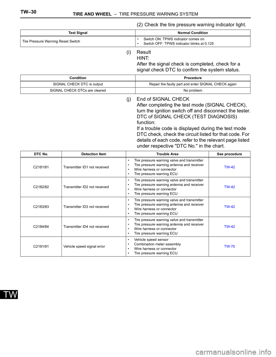
(2) Check the tire pressure warning indicator light.
(i) Result
HINT:
After the signal check is completed, check for a
signal check DTC to confirm the system status.
(j) End of SIGNAL CHECK
After completing the test mode (SIGNAL CHECK),
turn the ignition switch off and disconnect the tester.
DTC of SIGNAL CHECK (TEST DIAGNOSIS)
function:
If a trouble code is displayed during the test mode
DTC check, check the circuit listed for that code. For
details of each code, refer to the relevant page listed
under respective "DTC No." in the chart.
Test Signal Normal Condition
Tire Pressure Warning Reset Switch• Switch ON: TPWS indicator comes on
• Switch OFF: TPWS indicator blinks at 0.125
Condition Procedure
SIGNAL CHECK DTC is output Repair the faulty part and enter SIGNAL CHECK again
SIGNAL CHECK DTCs are cleared No problem
DTC No. Detection Item Trouble Area See procedure
C2181/81 Transmitter ID1 not received• Tire pressure warning valve and transmitter
• Tire pressure warning antenna and receiver
• Wire harness or connector
• Tire pressure warning ECUTW-42
C2182/82 Transmitter ID2 not received• Tire pressure warning valve and transmitter
• Tire pressure warning antenna and receiver
• Wire harness or connector
• Tire pressure warning ECUTW-42
C2183/83 Transmitter ID3 not received• Tire pressure warning valve and transmitter
• Tire pressure warning antenna and receiver
• Wire harness or connector
• Tire pressure warning ECUTW-42
C2184/84 Transmitter ID4 not received• Tire pressure warning valve and transmitter
• Tire pressure warning antenna and receiver
• Wire harness or connector
• Tire pressure warning ECUTW-42
C2191/91 Vehicle speed signal error• Vehicle speed sensor
• Combination meter assembly
• Wire harness or connector
• Tire pressure warning ECUTW-70
Page 2287 of 3000

TIRE AND WHEEL – TIRE PRESSURE WARNING SYSTEMTW–45
TW
DESCRIPTION
The tire pressure warning valve and transmitters that are installed in the tire and wheel assemblies
measure the air pressure of the tires. The measured values are transmitted to the tire pressure warning
antenna and receiver on the body as radio waves and then sent to the tire pressure warning ECU. The
ECU compares the measured air pressure values with the air pressure threshold. When the measured air
pressure value is less than this threshold, the warning light in the combination meter comes on.
The tire pressure warning valve and transmitters constantly send radio waves to the tire pressure warning
antenna and receiver.
Under the following conditions below, the tire pressure warning antenna and receiver is unable to receive
the signals from the tire pressure warning valves and transmitters, and a DTC is stored.
• Facilities or devices that use similar radio frequencies are located in the vicinity of the vehicle.
• Devices using similar radio frequencies are used in the vehicle.
• The goods which obstruct the radio signal of the valve and transmitter, for example, tire chain or
window film.
HINT:
When no signals are received for 20 minutes or more, a DTC is output.
DTCs from C2121/21 to C2124/24 can only be cleared by using the tester. DTCs from C2181/81 to
C2184/84 can be cleared when the transmitter in the tire pressure warning valve and transmitter sends a
forced transmission signal or test mode ends. DTCs from C2181/81 to C2184/84 are output only in test
mode.
HINT:
It is necessary to perform the procedure to identify the tire pressure warning valve and transmitter that is
malfunctioning because it cannot be identified by the output DTC.
DTC C2121/21 No Signal from Transmitter ID1
DTC C2122/22 No Signal from Transmitter ID2
DTC C2123/23 No Signal from Transmitter ID3
DTC C2124/24 No Signal from Transmitter ID4
DTC C2181/81 Transmitter ID1 not Received (Test Mode DTC)
DTC C2182/82 Transmitter ID2 not Received (Test Mode DTC)
DTC C2183/83 Transmitter ID3 not Received (Test Mode DTC)
DTC C2184/84 Transmitter ID4 not Received (Test Mode DTC)
DTC No. DTC Detection Condition Trouble Area
C2121/21
C2122/22
C2123/23
C2124/24These DTCs are detected when no signals are received
for 20 minute drive or more.• Tire pressure warning valve and transmitter
• Tire pressure warning antenna and receiver
• Wire harness or connector
• Tire pressure warning ECU
C2181/81
C2182/82
C2183/83
C2184/84Malfunction in the transmitting/receiving circuit• Tire pressure warning valve and transmitter
• Tire pressure warning antenna and receiver
• Wire harness or connector
• Tire pressure warning ECU
Page 2291 of 3000

TIRE AND WHEEL – TIRE PRESSURE WARNING SYSTEMTW–49
TW
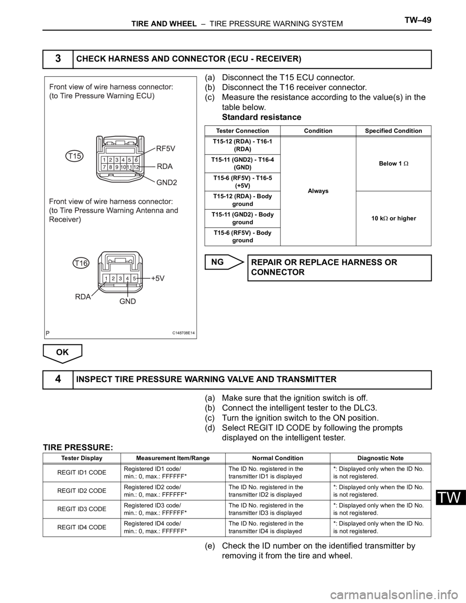
(a) Disconnect the T15 ECU connector.
(b) Disconnect the T16 receiver connector.
(c) Measure the resistance according to the value(s) in the
table below.
Standard resistance
NG
OK
(a) Make sure that the ignition switch is off.
(b) Connect the intelligent tester to the DLC3.
(c) Turn the ignition switch to the ON position.
(d) Select REGIT ID CODE by following the prompts
displayed on the intelligent tester.
TIRE PRESSURE:
(e) Check the ID number on the identified transmitter by
removing it from the tire and wheel.
3CHECK HARNESS AND CONNECTOR (ECU - RECEIVER)
C148708E14
Tester Connection Condition Specified Condition
T15-12 (RDA) - T16-1
(RDA)
AlwaysBelow 1
T15-11 (GND2) - T16-4
(GND)
T15-6 (RF5V) - T16-5
(+5V)
T15-12 (RDA) - Body
ground
10 k
or higher T15-11 (GND2) - Body
ground
T15-6 (RF5V) - Body
ground
REPAIR OR REPLACE HARNESS OR
CONNECTOR
4INSPECT TIRE PRESSURE WARNING VALVE AND TRANSMITTER
Tester Display Measurement Item/Range Normal Condition Diagnostic Note
REGIT ID1 CODERegistered ID1 code/
min.: 0, max.: FFFFFF*The ID No. registered in the
transmitter ID1 is displayed*: Displayed only when the ID No.
is not registered.
REGIT ID2 CODERegistered ID2 code/
min.: 0, max.: FFFFFF*The ID No. registered in the
transmitter ID2 is displayed*: Displayed only when the ID No.
is not registered.
REGIT ID3 CODERegistered ID3 code/
min.: 0, max.: FFFFFF*The ID No. registered in the
transmitter ID3 is displayed*: Displayed only when the ID No.
is not registered.
REGIT ID4 CODERegistered ID4 code/
min.: 0, max.: FFFFFF*The ID No. registered in the
transmitter ID4 is displayed*: Displayed only when the ID No.
is not registered.
Page 2305 of 3000

TIRE AND WHEEL – TIRE PRESSURE WARNING SYSTEMTW–63
TW
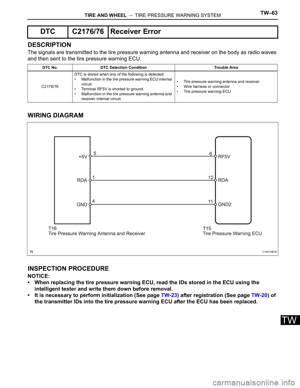
DESCRIPTION
The signals are transmitted to the tire pressure warning antenna and receiver on the body as radio waves
and then sent to the tire pressure warning ECU.
WIRING DIAGRAM
INSPECTION PROCEDURE
NOTICE:
• When replacing the tire pressure warning ECU, read the IDs stored in the ECU using the
intelligent tester and write them down before removal.
• It is necessary to perform initialization (See page TW-23) after registration (See page TW-20) of
the transmitter IDs into the tire pressure warning ECU after the ECU has been replaced.
DTC C2176/76 Receiver Error
DTC No. DTC Detection Condition Trouble Area
C2176/76DTC is stored when any of the following is detected:
• Malfunction in the tire pressure warning ECU internal
circuit.
• Terminal RF5V is shorted to ground.
• Malfunction in the tire pressure warning antenna and
receiver internal circuit.• Tire pressure warning antenna and receiver
• Wire harness or connector
• Tire pressure warning ECU
C148709E08