2007 TOYOTA SIENNA ecu harness
[x] Cancel search: ecu harnessPage 855 of 3000
MP–12MULTIPLEX COMMUNICATION – MULTIPLEX COMMUNICATION SYSTEM
MP
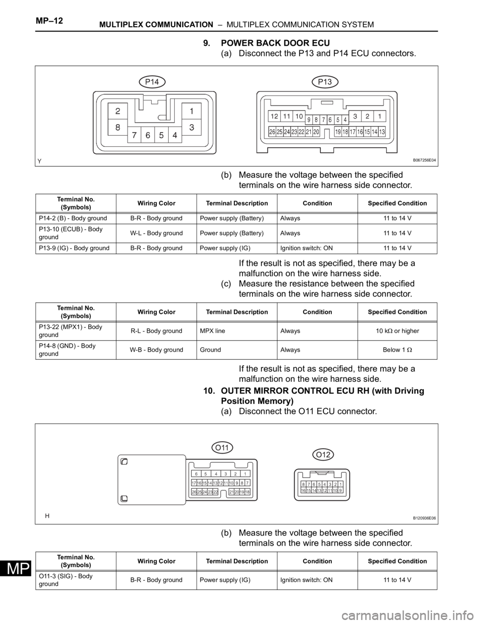
9. POWER BACK DOOR ECU
(a) Disconnect the P13 and P14 ECU connectors.
(b) Measure the voltage between the specified
terminals on the wire harness side connector.
If the result is not as specified, there may be a
malfunction on the wire harness side.
(c) Measure the resistance between the specified
terminals on the wire harness side connector.
If the result is not as specified, there may be a
malfunction on the wire harness side.
10. OUTER MIRROR CONTROL ECU RH (with Driving
Position Memory)
(a) Disconnect the O11 ECU connector.
(b) Measure the voltage between the specified
terminals on the wire harness side connector.
B067256E04
Te r m i n a l N o .
(Symbols)Wiring Color Terminal Description Condition Specified Condition
P14-2 (B) - Body ground B-R - Body ground Power supply (Battery) Always 11 to 14 V
P13-10 (ECUB) - Body
groundW-L - Body ground Power supply (Battery) Always 11 to 14 V
P13-9 (IG) - Body ground B-R - Body ground Power supply (IG) Ignition switch: ON 11 to 14 V
Te r m i n a l N o .
(Symbols)Wiring Color Terminal Description Condition Specified Condition
P13-22 (MPX1) - Body
groundR-L - Body ground MPX line Always 10 k
or higher
P14-8 (GND) - Body
groundW-B - Body ground Ground Always Below 1
B120936E06
Te r m i n a l N o .
(Symbols)Wiring Color Terminal Description Condition Specified Condition
O11-3 (SIG) - Body
groundB-R - Body ground Power supply (IG) Ignition switch: ON 11 to 14 V
Page 856 of 3000
MULTIPLEX COMMUNICATION – MULTIPLEX COMMUNICATION SYSTEMMP–13
MP
If the result is not as specified, there may be a
malfunction on the wire harness side.
(c) Measure the resistance between the specified
terminals on the wire harness side connector.
If the result is not as specified, there may be a
malfunction on the wire harness side.
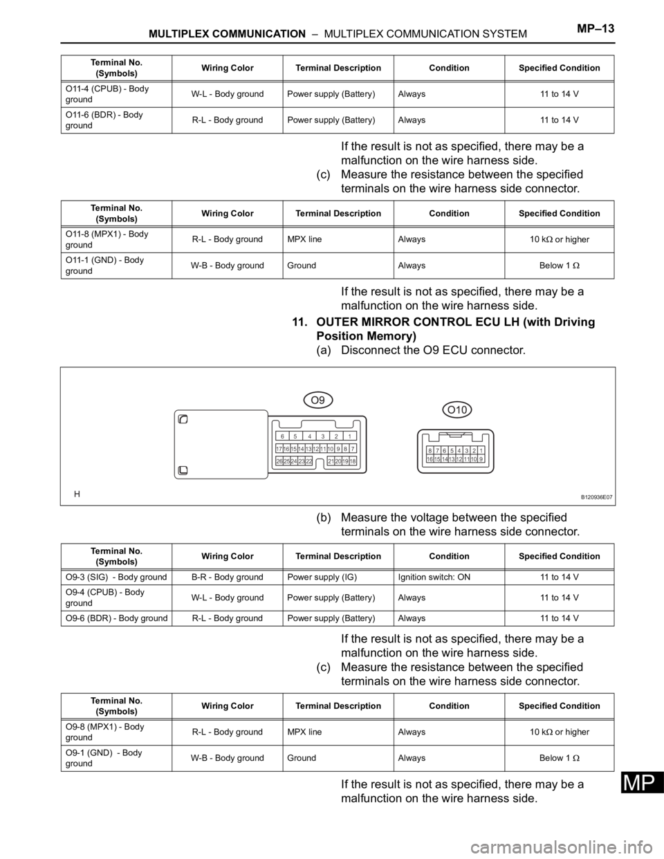
11. OUTER MIRROR CONTROL ECU LH (with Driving
Position Memory)
(a) Disconnect the O9 ECU connector.
(b) Measure the voltage between the specified
terminals on the wire harness side connector.
If the result is not as specified, there may be a
malfunction on the wire harness side.
(c) Measure the resistance between the specified
terminals on the wire harness side connector.
If the result is not as specified, there may be a
malfunction on the wire harness side.
O11-4 (CPUB) - Body
groundW-L - Body ground Power supply (Battery) Always 11 to 14 V
O11-6 (BDR) - Body
groundR-L - Body ground Power supply (Battery) Always 11 to 14 V Terminal No.
(Symbols)Wiring Color Terminal Description Condition Specified Condition
Terminal No.
(Symbols)Wiring Color Terminal Description Condition Specified Condition
O11-8 (MPX1) - Body
groundR-L - Body ground MPX line Always 10 k
or higher
O11-1 (GND) - Body
groundW-B - Body ground Ground Always Below 1
B120936E07
Terminal No.
(Symbols)Wiring Color Terminal Description Condition Specified Condition
O9-3 (SIG) - Body ground B-R - Body ground Power supply (IG) Ignition switch: ON 11 to 14 V
O9-4 (CPUB) - Body
groundW-L - Body ground Power supply (Battery) Always 11 to 14 V
O9-6 (BDR) - Body ground R-L - Body ground Power supply (Battery)Always 11 to 14 V
Terminal No.
(Symbols)Wiring Color Terminal Description Condition Specified Condition
O9-8 (MPX1) - Body
groundR-L - Body ground MPX line Always 10 k
or higher
O9-1 (GND) - Body
groundW-B - Body ground Ground Always Below 1
Page 1167 of 3000
FU–442GR-FE FUEL – FUEL TANK
FU
INSTALLATION
1. CONNECT FUEL TANK VENT HOSE
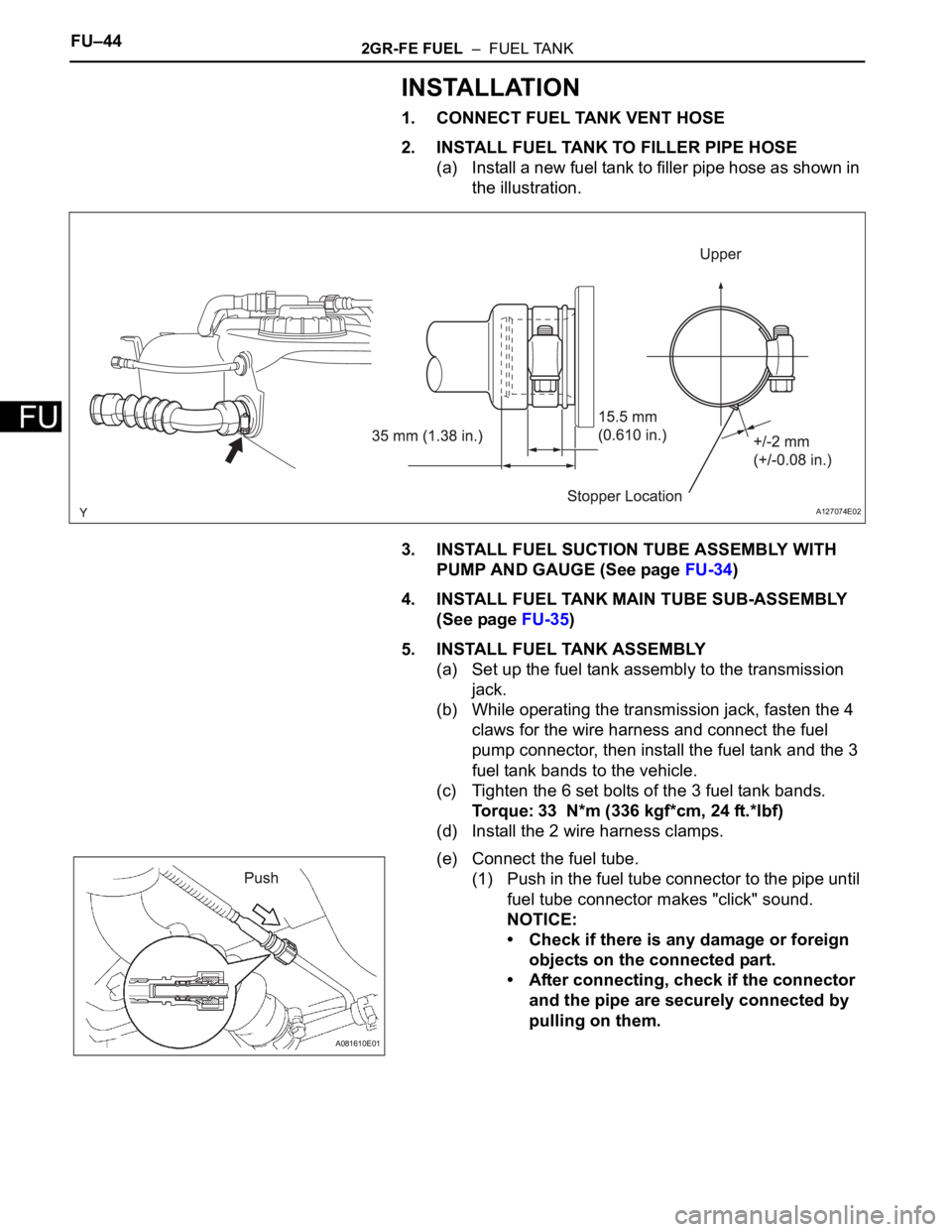
2. INSTALL FUEL TANK TO FILLER PIPE HOSE
(a) Install a new fuel tank to filler pipe hose as shown in
the illustration.
3. INSTALL FUEL SUCTION TUBE ASSEMBLY WITH
PUMP AND GAUGE (See page FU-34)
4. INSTALL FUEL TANK MAIN TUBE SUB-ASSEMBLY
(See page FU-35)
5. INSTALL FUEL TANK ASSEMBLY
(a) Set up the fuel tank assembly to the transmission
jack.
(b) While operating the transmission jack, fasten the 4
claws for the wire harness and connect the fuel
pump connector, then install the fuel tank and the 3
fuel tank bands to the vehicle.
(c) Tighten the 6 set bolts of the 3 fuel tank bands.
Torque: 33 N*m (336 kgf*cm, 24 ft.*lbf)
(d) Install the 2 wire harness clamps.
(e) Connect the fuel tube.
(1) Push in the fuel tube connector to the pipe until
fuel tube connector makes "click" sound.
NOTICE:
• Check if there is any damage or foreign
objects on the connected part.
• After connecting, check if the connector
and the pipe are securely connected by
pulling on them.
A127074E02
A081610E01
Page 1170 of 3000
FU–442GR-FE FUEL – FUEL TANK
FU
INSTALLATION
1. CONNECT FUEL TANK VENT HOSE
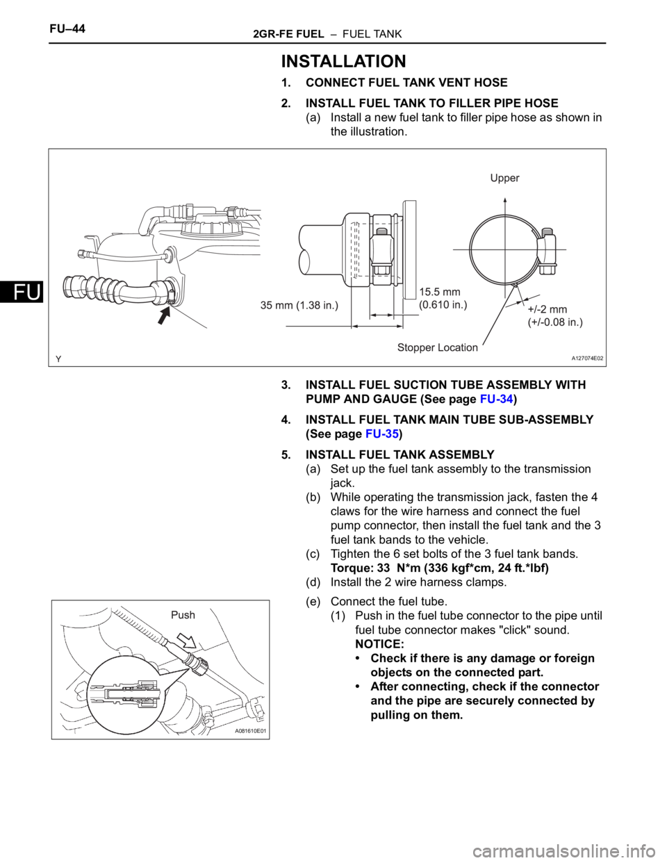
2. INSTALL FUEL TANK TO FILLER PIPE HOSE
(a) Install a new fuel tank to filler pipe hose as shown in
the illustration.
3. INSTALL FUEL SUCTION TUBE ASSEMBLY WITH
PUMP AND GAUGE (See page FU-34)
4. INSTALL FUEL TANK MAIN TUBE SUB-ASSEMBLY
(See page FU-35)
5. INSTALL FUEL TANK ASSEMBLY
(a) Set up the fuel tank assembly to the transmission
jack.
(b) While operating the transmission jack, fasten the 4
claws for the wire harness and connect the fuel
pump connector, then install the fuel tank and the 3
fuel tank bands to the vehicle.
(c) Tighten the 6 set bolts of the 3 fuel tank bands.
Torque: 33 N*m (336 kgf*cm, 24 ft.*lbf)
(d) Install the 2 wire harness clamps.
(e) Connect the fuel tube.
(1) Push in the fuel tube connector to the pipe until
fuel tube connector makes "click" sound.
NOTICE:
• Check if there is any damage or foreign
objects on the connected part.
• After connecting, check if the connector
and the pipe are securely connected by
pulling on them.
A127074E02
A081610E01
Page 1368 of 3000
CH–282GR-FE CHARGING – GENERATOR
CH
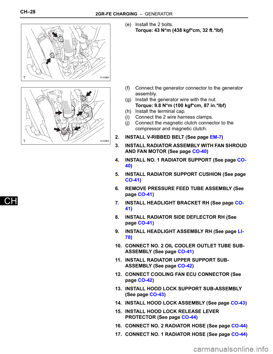
(e) Install the 2 bolts.
Torque: 43 N*m (438 kgf*cm, 32 ft.*lbf)
(f) Connect the generator connector to the generator
assembly.
(g) Install the generator wire with the nut.
Torque: 9.8 N*m (100 kgf*cm, 87 in.*lbf)
(h) Install the terminal cap.
(i) Connect the 2 wire harness clamps.
(j) Connect the magnetic clutch connector to the
compressor and magnetic clutch.
2. INSTALL V-RIBBED BELT (See page EM-7)
3. INSTALL RADIATOR ASSEMBLY WITH FAN SHROUD
AND FAN MOTOR (See page CO-40)
4. INSTALL NO. 1 RADIATOR SUPPORT (See page CO-
40)
5. INSTALL RADIATOR SUPPORT CUSHION (See page
CO-41)
6. REMOVE PRESSURE FEED TUBE ASSEMBLY (See
page CO-41)
7. INSTALL HEADLIGHT BRACKET RH (See page CO-
41)
8. INSTALL RADIATOR SIDE DEFLECTOR RH (See
page CO-41)
9. INSTALL HEADLIGHT ASSEMBLY RH (See page LI-
78)
10. CONNECT NO. 2 OIL COOLER OUTLET TUBE SUB-
ASSEMBLY (See page CO-41)
11. INSTALL RADIATOR UPPER SUPPORT SUB-
ASSEMBLY (See page CO-42)
12. CONNECT COOLING FAN ECU CONNECTOR (See
page CO-42)
13. INSTALL HOOD LOCK SUPPORT SUB-ASSEMBLY
(See page CO-43)
14. INSTALL HOOD LOCK ASSEMBLY (See page CO-43)
15. INSTALL HOOD LOCK RELEASE LEVER
PROTECTOR (See page CO-44)
16. CONNECT NO. 2 RADIATOR HOSE (See page CO-44)
17. CONNECT NO. 1 RADIATOR HOSE (See page CO-44)
A133866
A133865
Page 1377 of 3000
CH–282GR-FE CHARGING – GENERATOR
CH
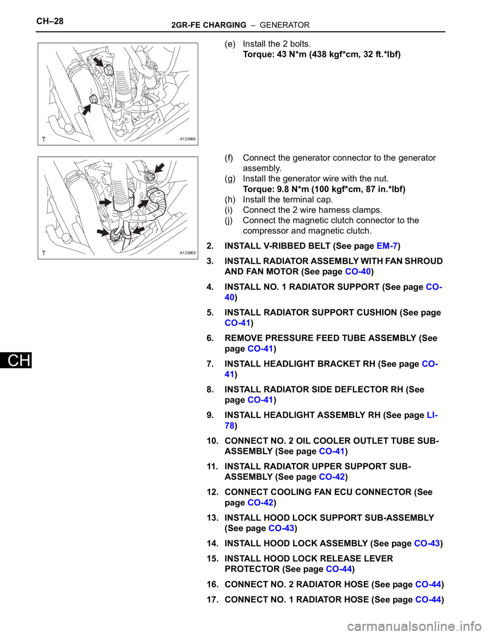
(e) Install the 2 bolts.
Torque: 43 N*m (438 kgf*cm, 32 ft.*lbf)
(f) Connect the generator connector to the generator
assembly.
(g) Install the generator wire with the nut.
Torque: 9.8 N*m (100 kgf*cm, 87 in.*lbf)
(h) Install the terminal cap.
(i) Connect the 2 wire harness clamps.
(j) Connect the magnetic clutch connector to the
compressor and magnetic clutch.
2. INSTALL V-RIBBED BELT (See page EM-7)
3. INSTALL RADIATOR ASSEMBLY WITH FAN SHROUD
AND FAN MOTOR (See page CO-40)
4. INSTALL NO. 1 RADIATOR SUPPORT (See page CO-
40)
5. INSTALL RADIATOR SUPPORT CUSHION (See page
CO-41)
6. REMOVE PRESSURE FEED TUBE ASSEMBLY (See
page CO-41)
7. INSTALL HEADLIGHT BRACKET RH (See page CO-
41)
8. INSTALL RADIATOR SIDE DEFLECTOR RH (See
page CO-41)
9. INSTALL HEADLIGHT ASSEMBLY RH (See page LI-
78)
10. CONNECT NO. 2 OIL COOLER OUTLET TUBE SUB-
ASSEMBLY (See page CO-41)
11. INSTALL RADIATOR UPPER SUPPORT SUB-
ASSEMBLY (See page CO-42)
12. CONNECT COOLING FAN ECU CONNECTOR (See
page CO-42)
13. INSTALL HOOD LOCK SUPPORT SUB-ASSEMBLY
(See page CO-43)
14. INSTALL HOOD LOCK ASSEMBLY (See page CO-43)
15. INSTALL HOOD LOCK RELEASE LEVER
PROTECTOR (See page CO-44)
16. CONNECT NO. 2 RADIATOR HOSE (See page CO-44)
17. CONNECT NO. 1 RADIATOR HOSE (See page CO-44)
A133866
A133865
Page 1411 of 3000
U151E AUTOMATIC TRANSAXLE – AUTOMATIC TRANSAXLE SYSTEMAX–45
AX
DESCRIPTION
The park/neutral position switch detects the shift lever position and sends signals to the ECM.
MONITOR DESCRIPTION
These DTCs indicate a problem with the park/neutral position switch and the wire harness in the park/
neutral position switch circuit.
The park/neutral position switch detects the shift lever position and sends a signal to the ECM.
For security, the park/neutral position switch detects the shift lever position so that engine can be started
only when the shift lever is in the P or N position
The park/neutral position switch sends a signal to the ECM according to the shift position (P, R, N or D).
The ECM determines that there is a problem with the switch or related parts if in receives more than 1
position signal simultaneously. The ECM will turn on the MIL and store the DTC.
MONITOR STRATEGY
DTC P0705Transmission Range Sensor Circuit Malfunc-
tion (PRNDL Input)
DTC No. DTC Detection Condition Trouble Area
P0705(A) Any 2 or more signals of the following are ON
simultaneously (2-trip detection logic)
• P input signal is ON.
• N input signal is ON.
• R input signal is ON.
• D input signal is ON.
• 3 input signal is ON.
• 2 input signal is ON.
(B) Any 2 or more signals of the following are ON
simultaneously (2-trip detection logic)
• NSW (STAR) input signal is ON.
• R input signal is ON.
• D input signal is ON.
• 3 input signal is ON.
• 2 input signal is ON.
(C) All switches are OFF simultaneously for NSW
(STAR), P, R, N, D, 3, 2 positions (2-trip detection
logic).
(D) Both 1 and 2 conditions are met (2-trip detection
logic)
1. One of the following conditions are met
(a) NSW (STAR) input signal is ON.
(b) P input signal is ON.
(c) N input signal is ON.
(d) R input signal is ON.
2. One of the following conditions are met
(a) 4 input signal is ON.
(b) L input signal is ON.• Short in park/neutral position switch circuit
• Park/neutral position switch
•ECM
Related DTCs P0705: Park/neutral position switch/Verify switch input
Required sensors/Components Park/neutral position switch
Frequency of operation Continuous
DurationCondition (A), (B), (D)
2 sec.
Condition (C)
60 sec.
MIL operation 2 driving cycles
Sequence of operation None
Page 1437 of 3000
U151E AUTOMATIC TRANSAXLE – AUTOMATIC TRANSAXLE SYSTEMAX–71
AX
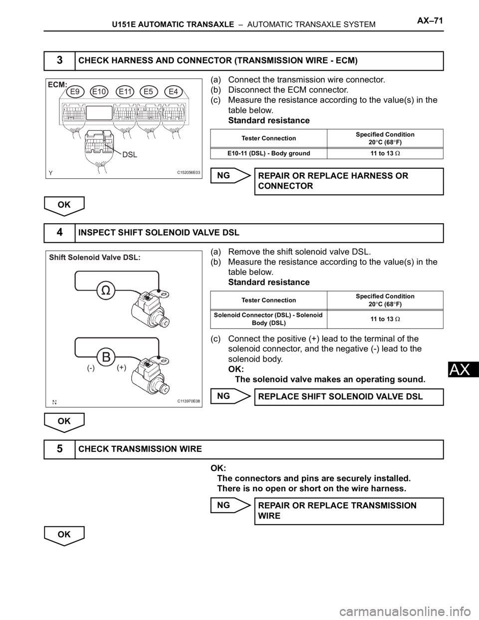
(a) Connect the transmission wire connector.
(b) Disconnect the ECM connector.
(c) Measure the resistance according to the value(s) in the
table below.
Standard resistance
NG
OK
(a) Remove the shift solenoid valve DSL.
(b) Measure the resistance according to the value(s) in the
table below.
Standard resistance
(c) Connect the positive (+) lead to the terminal of the
solenoid connector, and the negative (-) lead to the
solenoid body.
OK:
The solenoid valve makes an operating sound.
NG
OK
OK:
The connectors and pins are securely installed.
There is no open or short on the wire harness.
NG
OK
3CHECK HARNESS AND CONNECTOR (TRANSMISSION WIRE - ECM)
C152056E03
Tester ConnectionSpecified Condition
20C (68F)
E10-11 (DSL) - Body ground 11 to 13
REPAIR OR REPLACE HARNESS OR
CONNECTOR
4INSPECT SHIFT SOLENOID VALVE DSL
C113970E08
Tester ConnectionSpecified Condition
20C (68F)
Solenoid Connector (DSL) - Solenoid
Body (DSL)11 to 13
REPLACE SHIFT SOLENOID VALVE DSL
5CHECK TRANSMISSION WIRE
REPAIR OR REPLACE TRANSMISSION
WIRE