Page 65 of 3000
INTRODUCTION – HOW TO TROUBLESHOOT ECU CONTROLLED SYSTEMSIN–35
IN
(a) First, check the ECU ground circuit. If it is faulty,
repair it. If it is normal, the ECU could be faulty.
Temporarily replace the ECU with a normally
functioning one and check if the symptoms occur. If
the trouble symptoms disappear, replace the
original ECU.
(1) Measure the resistance between the ECU
ground terminal and body ground.
Standard resistance:
Below 1
(2) Disconnect the ECU connector. Check the
ground terminal on the ECU side and wire
harness side for bending, corrosion or foreign
matter. Lastly, check the contact pressure of the
female terminals.
IN00383E02
IN00384E03
Page 66 of 3000
IN–36INTRODUCTION – HOW TO TROUBLESHOOT ECU CONTROLLED SYSTEMS
IN
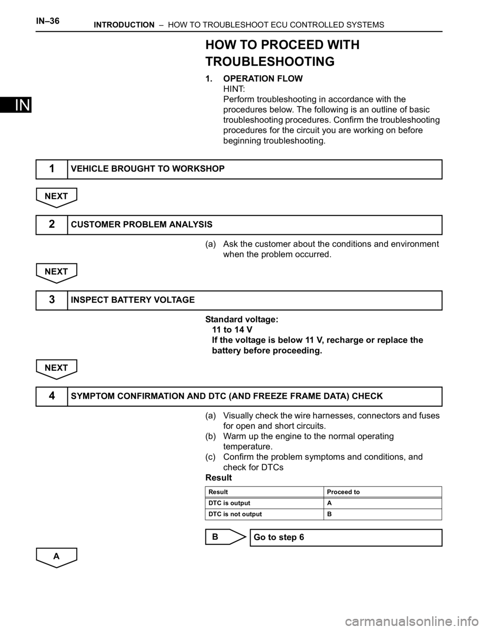
HOW TO PROCEED WITH
TROUBLESHOOTING
1. OPERATION FLOW
HINT:
Perform troubleshooting in accordance with the
procedures below. The following is an outline of basic
troubleshooting procedures. Confirm the troubleshooting
procedures for the circuit you are working on before
beginning troubleshooting.
NEXT
(a) Ask the customer about the conditions and environment
when the problem occurred.
NEXT
Standard voltage:
11 to 14 V
If the voltage is below 11 V, recharge or replace the
battery before proceeding.
NEXT
(a) Visually check the wire harnesses, connectors and fuses
for open and short circuits.
(b) Warm up the engine to the normal operating
temperature.
(c) Confirm the problem symptoms and conditions, and
check for DTCs
Result
B
A
1VEHICLE BROUGHT TO WORKSHOP
2CUSTOMER PROBLEM ANALYSIS
3INSPECT BATTERY VOLTAGE
4SYMPTOM CONFIRMATION AND DTC (AND FREEZE FRAME DATA) CHECK
Result Proceed to
DTC is output A
DTC is not output B
Go to step 6
Page 71 of 3000

INTRODUCTION – HOW TO TROUBLESHOOT ECU CONTROLLED SYSTEMSIN–41
IN
If a DTC was displayed in the initial DTC check, the
problem may have occurred in a wire harness or
connector in that circuit in the past. Check the wire
harness and connectors.
B
A
The problem still occurs in a place other than the diagnostic
circuit (the DTC displayed first is either for a past problem or
a secondary problem).
4. SYMPTOM SIMULATION
HINT:
The most difficult case in troubleshooting is when no
problem symptoms occur. In such a case, a thorough
problem analysis must be carried out. A simulation of the
same or similar conditions and environment in which the
problem occurred in the customer's vehicle should be
carried out. No matter how much skill or experience a
technician has, troubleshooting without confirming the
problem symptoms will lead to important repairs being
overlooked and mistakes or delays.
For example:
With a problem that only occurs when the engine is
cold or as a result of vibration caused by the road
during driving, the problem can never be
determined if the symptoms are being checked on
a stationary vehicle or a vehicle with a warmed-up
engine. Vibration, heat or water penetration
(moisture) is difficult to reproduce. The symptom
simulation tests below are effective substitutes for
the conditions and can be applied on a stationary
vehicle. Important points in the symptom
simulation test:
In the symptom simulation test, the problem
symptoms as well as the problem area or parts
must be confirmed. First, narrow down the
possible problem circuits according to the
symptoms. Then, connect the tester and carry out
the symptom simulation test, judging whether the
circuit being tested is defective or normal. Also,
confirm the problem symptoms at the same time.
Refer to the problem symptoms table for each
system to narrow down the possible causes.SYSTEM NORMAL
TROUBLESHOOTING OF EACH PROBLEM SYMPTOM
Page 72 of 3000
IN–42INTRODUCTION – HOW TO TROUBLESHOOT ECU CONTROLLED SYSTEMS
IN
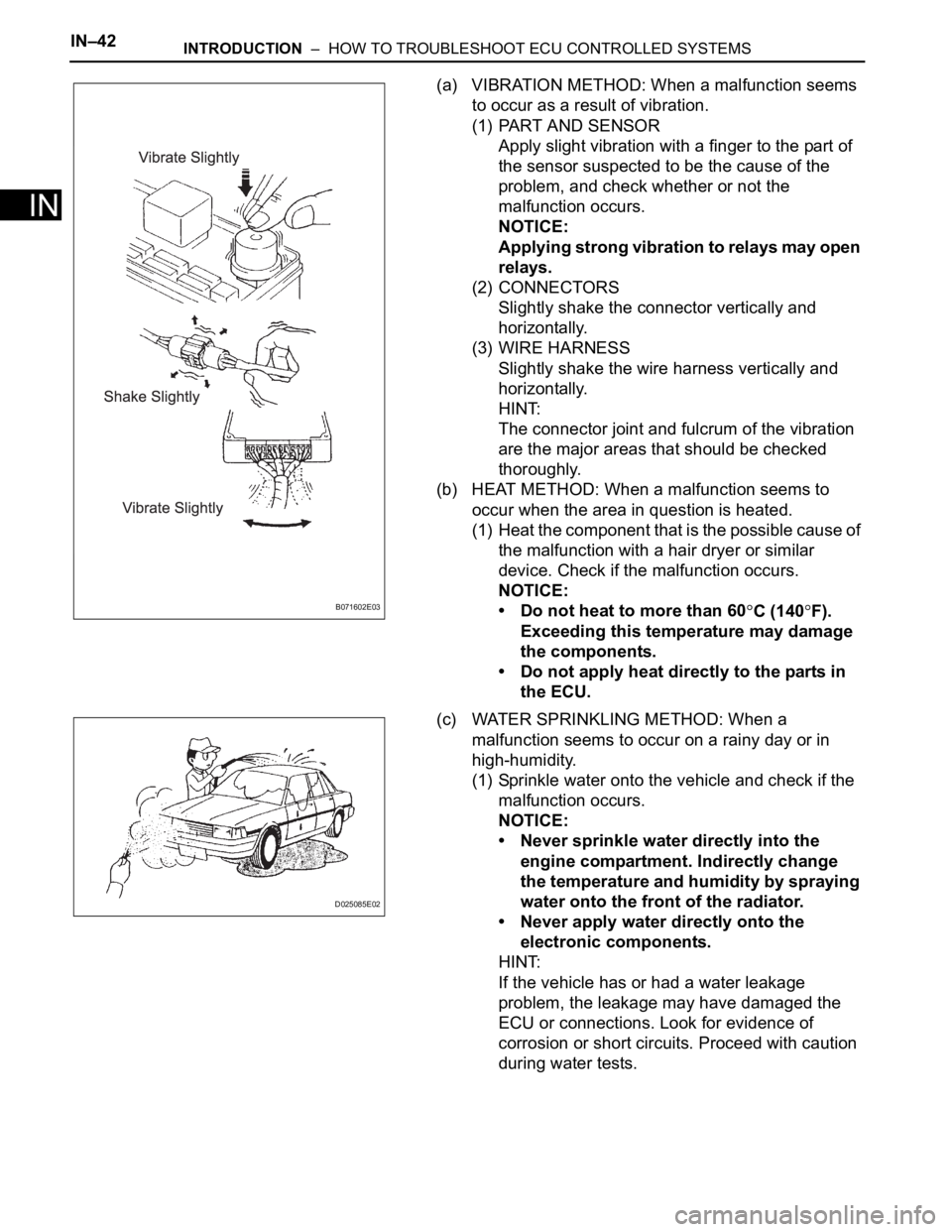
(a) VIBRATION METHOD: When a malfunction seems
to occur as a result of vibration.
(1) PART AND SENSOR
Apply slight vibration with a finger to the part of
the sensor suspected to be the cause of the
problem, and check whether or not the
malfunction occurs.
NOTICE:
Applying strong vibration to relays may open
relays.
(2) CONNECTORS
Slightly shake the connector vertically and
horizontally.
(3) WIRE HARNESS
Slightly shake the wire harness vertically and
horizontally.
HINT:
The connector joint and fulcrum of the vibration
are the major areas that should be checked
thoroughly.
(b) HEAT METHOD: When a malfunction seems to
occur when the area in question is heated.
(1) Heat the component that is the possible cause of
the malfunction with a hair dryer or similar
device. Check if the malfunction occurs.
NOTICE:
• Do not heat to more than 60
C (140F).
Exceeding this temperature may damage
the components.
• Do not apply heat directly to the parts in
the ECU.
(c) WATER SPRINKLING METHOD: When a
malfunction seems to occur on a rainy day or in
high-humidity.
(1) Sprinkle water onto the vehicle and check if the
malfunction occurs.
NOTICE:
• Never sprinkle water directly into the
engine compartment. Indirectly change
the temperature and humidity by spraying
water onto the front of the radiator.
• Never apply water directly onto the
electronic components.
HINT:
If the vehicle has or had a water leakage
problem, the leakage may have damaged the
ECU or connections. Look for evidence of
corrosion or short circuits. Proceed with caution
during water tests.B071602E03
D025085E02
Page 74 of 3000
IN–44INTRODUCTION – HOW TO TROUBLESHOOT ECU CONTROLLED SYSTEMS
IN
Inspection Procedures Use the inspection procedures to determine if the circuit is normal or
abnormal. If abnormal, use the inspection procedures to determine
whether the problem is located in the sensors, actuators, wire
harnesses or ECU.
Indicates the condition of the connector of the ECU during the check Connector being checked is connected.
Connections of tester are indicated by (+) or (-) after the terminal
name.
Connector being checked is disconnected.
The inspections between a connector and body ground, information
about the body ground is not shown in the illustration. Item Description
Page 382 of 3000
ES–762GR-FE ENGINE CONTROL SYSTEM – SFI SYSTEM
ES
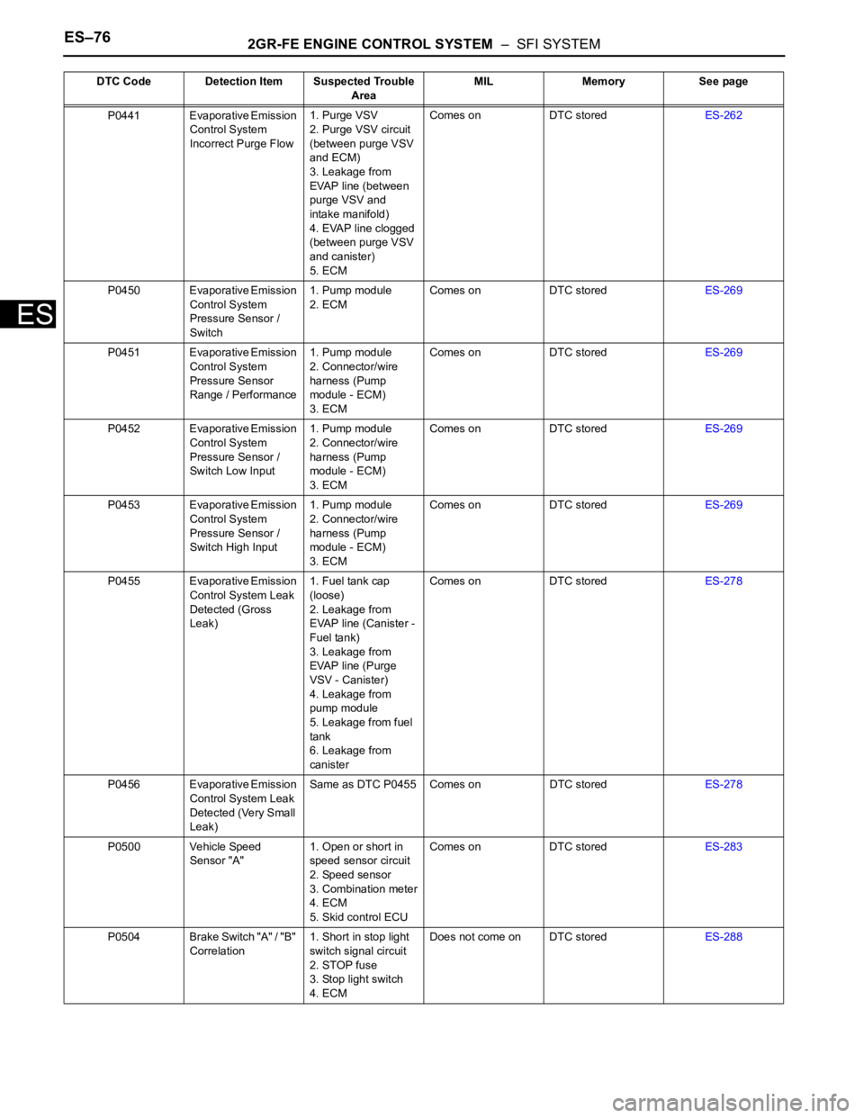
P0441 Evaporative Emission
Control System
Incorrect Purge Flow1. Purge VSV
2. Purge VSV circuit
(between purge VSV
and ECM)
3. Leakage from
EVAP line (between
purge VSV and
intake manifold)
4. EVAP line clogged
(between purge VSV
and canister)
5. ECMComes on DTC storedES-262
P0450 Evaporative Emission
Control System
Pressure Sensor /
Switch1. Pump module
2. ECMComes on DTC storedES-269
P0451 Evaporative Emission
Control System
Pressure Sensor
Range / Performance1. Pump module
2. Connector/wire
harness (Pump
module - ECM)
3. ECMComes on DTC storedES-269
P0452 Evaporative Emission
Control System
Pressure Sensor /
Switch Low Input1. Pump module
2. Connector/wire
harness (Pump
module - ECM)
3. ECMComes on DTC storedES-269
P0453 Evaporative Emission
Control System
Pressure Sensor /
Switch High Input1. Pump module
2. Connector/wire
harness (Pump
module - ECM)
3. ECMComes on DTC storedES-269
P0455 Evaporative Emission
Control System Leak
Detected (Gross
Leak)1. Fuel tank cap
(loose)
2. Leakage from
EVAP line (Canister -
Fuel tank)
3. Leakage from
EVAP line (Purge
VSV - Canister)
4. Leakage from
pump module
5. Leakage from fuel
tank
6. Leakage from
canisterComes on DTC storedES-278
P0456 Evaporative Emission
Control System Leak
Detected (Very Small
Leak)Same as DTC P0455 Comes on DTC storedES-278
P0500 Vehicle Speed
Sensor "A"1. Open or short in
speed sensor circuit
2. Speed sensor
3. Combination meter
4. ECM
5. Skid control ECUComes on DTC storedES-283
P0504 Brake Switch "A" / "B"
Correlation1. Short in stop light
switch signal circuit
2. STOP fuse
3. Stop light switch
4. ECMDoes not come on DTC storedES-288 DTC Code Detection Item Suspected Trouble
AreaMIL Memory See page
Page 421 of 3000
2GR-FE ENGINE CONTROL SYSTEM – SFI SYSTEMES–115
ES
OK
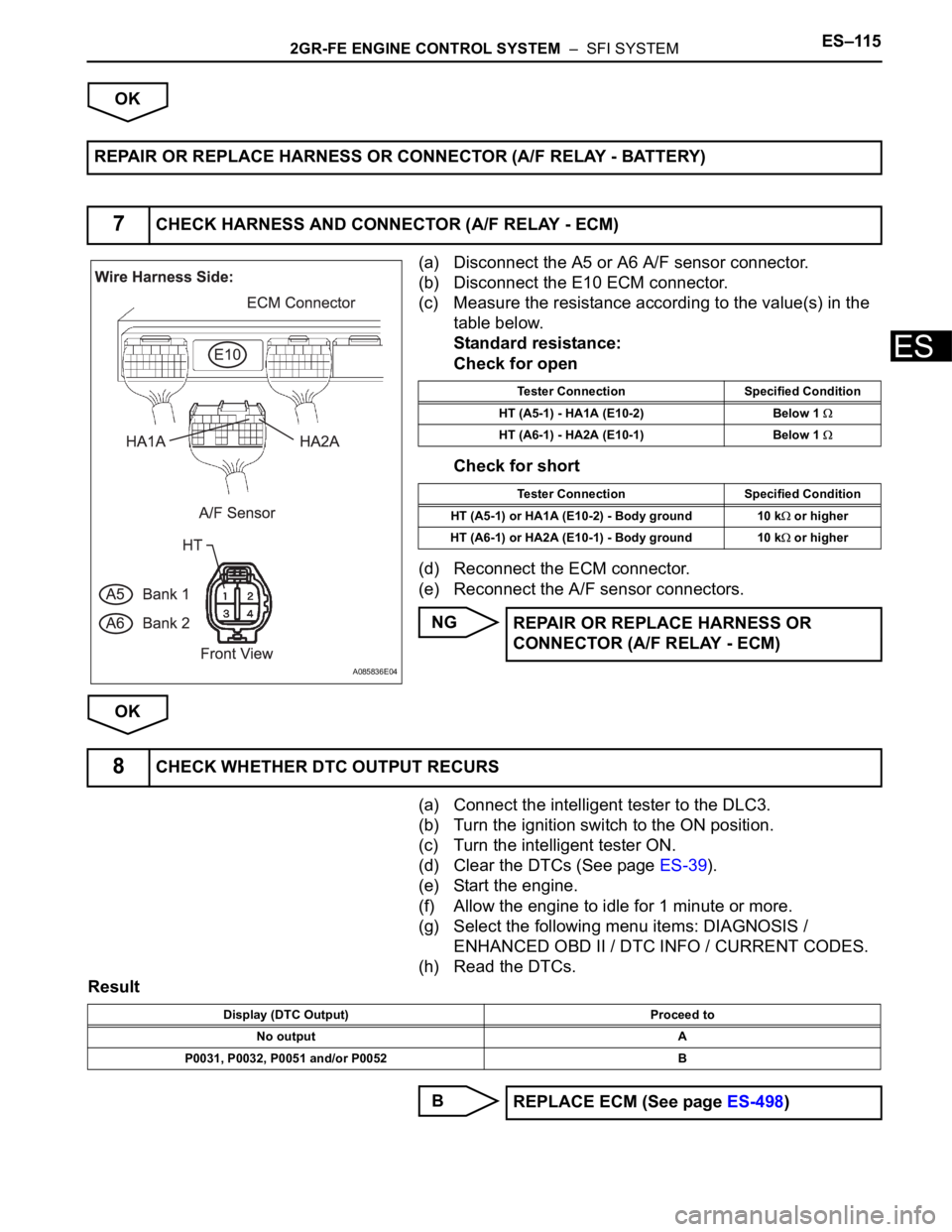
(a) Disconnect the A5 or A6 A/F sensor connector.
(b) Disconnect the E10 ECM connector.
(c) Measure the resistance according to the value(s) in the
table below.
Standard resistance:
Check for open
Check for short
(d) Reconnect the ECM connector.
(e) Reconnect the A/F sensor connectors.
NG
OK
(a) Connect the intelligent tester to the DLC3.
(b) Turn the ignition switch to the ON position.
(c) Turn the intelligent tester ON.
(d) Clear the DTCs (See page ES-39).
(e) Start the engine.
(f) Allow the engine to idle for 1 minute or more.
(g) Select the following menu items: DIAGNOSIS /
ENHANCED OBD II / DTC INFO / CURRENT CODES.
(h) Read the DTCs.
Result
B REPAIR OR REPLACE HARNESS OR CONNECTOR (A/F RELAY - BATTERY)
7CHECK HARNESS AND CONNECTOR (A/F RELAY - ECM)
A085836E04
Tester Connection Specified Condition
HT (A5-1) - HA1A (E10-2) Below 1
HT (A6-1) - HA2A (E10-1) Below 1
Tester Connection Specified Condition
HT (A5-1) or HA1A (E10-2) - Body ground 10 k
or higher
HT (A6-1) or HA2A (E10-1) - Body ground 10 k
or higher
REPAIR OR REPLACE HARNESS OR
CONNECTOR (A/F RELAY - ECM)
8CHECK WHETHER DTC OUTPUT RECURS
Display (DTC Output) Proceed to
No output A
P0031, P0032, P0051 and/or P0052 B
REPLACE ECM (See page ES-498)
Page 654 of 3000
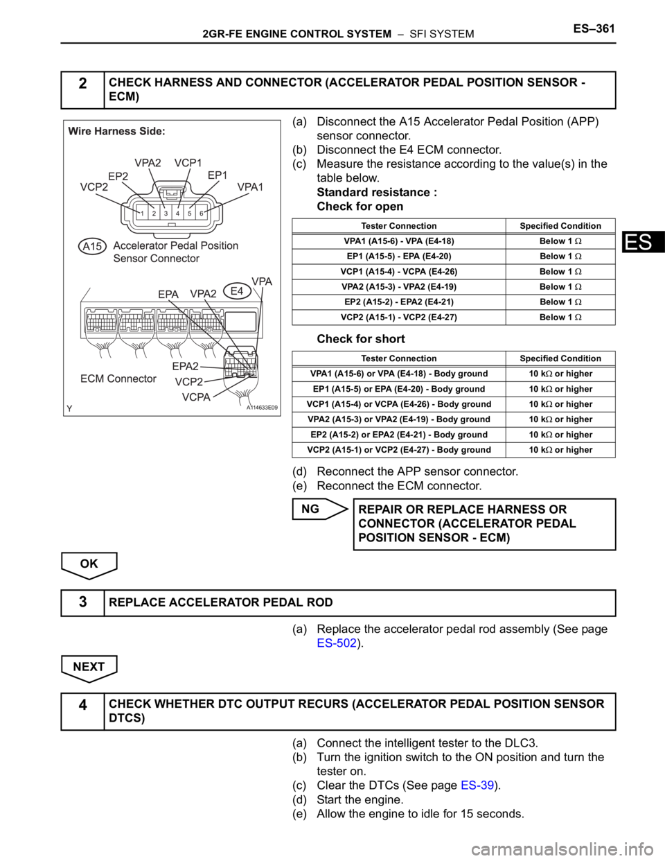
2GR-FE ENGINE CONTROL SYSTEM – SFI SYSTEMES–361
ES
(a) Disconnect the A15 Accelerator Pedal Position (APP)
sensor connector.
(b) Disconnect the E4 ECM connector.
(c) Measure the resistance according to the value(s) in the
table below.
Standard resistance :
Check for open
Check for short
(d) Reconnect the APP sensor connector.
(e) Reconnect the ECM connector.
NG
OK
(a) Replace the accelerator pedal rod assembly (See page
ES-502).
NEXT
(a) Connect the intelligent tester to the DLC3.
(b) Turn the ignition switch to the ON position and turn the
tester on.
(c) Clear the DTCs (See page ES-39).
(d) Start the engine.
(e) Allow the engine to idle for 15 seconds.
2CHECK HARNESS AND CONNECTOR (ACCELERATOR PEDAL POSITION SENSOR -
ECM)
A114633E09
Tester Connection Specified Condition
VPA1 (A15-6) - VPA (E4-18) Below 1
EP1 (A15-5) - EPA (E4-20) Below 1
VCP1 (A15-4) - VCPA (E4-26) Below 1
VPA2 (A15-3) - VPA2 (E4-19) Below 1
EP2 (A15-2) - EPA2 (E4-21) Below 1
VCP2 (A15-1) - VCP2 (E4-27) Below 1
Tester Connection Specified Condition
VPA1 (A15-6) or VPA (E4-18) - Body ground 10 k
or higher
EP1 (A15-5) or EPA (E4-20) - Body ground 10 k
or higher
VCP1 (A15-4) or VCPA (E4-26) - Body ground 10 k
or higher
VPA2 (A15-3) or VPA2 (E4-19) - Body ground 10 k
or higher
EP2 (A15-2) or EPA2 (E4-21) - Body ground 10 k
or higher
VCP2 (A15-1) or VCP2 (E4-27) - Body ground 10 k
or higher
REPAIR OR REPLACE HARNESS OR
CONNECTOR (ACCELERATOR PEDAL
POSITION SENSOR - ECM)
3REPLACE ACCELERATOR PEDAL ROD
4CHECK WHETHER DTC OUTPUT RECURS (ACCELERATOR PEDAL POSITION SENSOR
DTCS)