Page 2306 of 3000
TW–64TIRE AND WHEEL – TIRE PRESSURE WARNING SYSTEM
TW
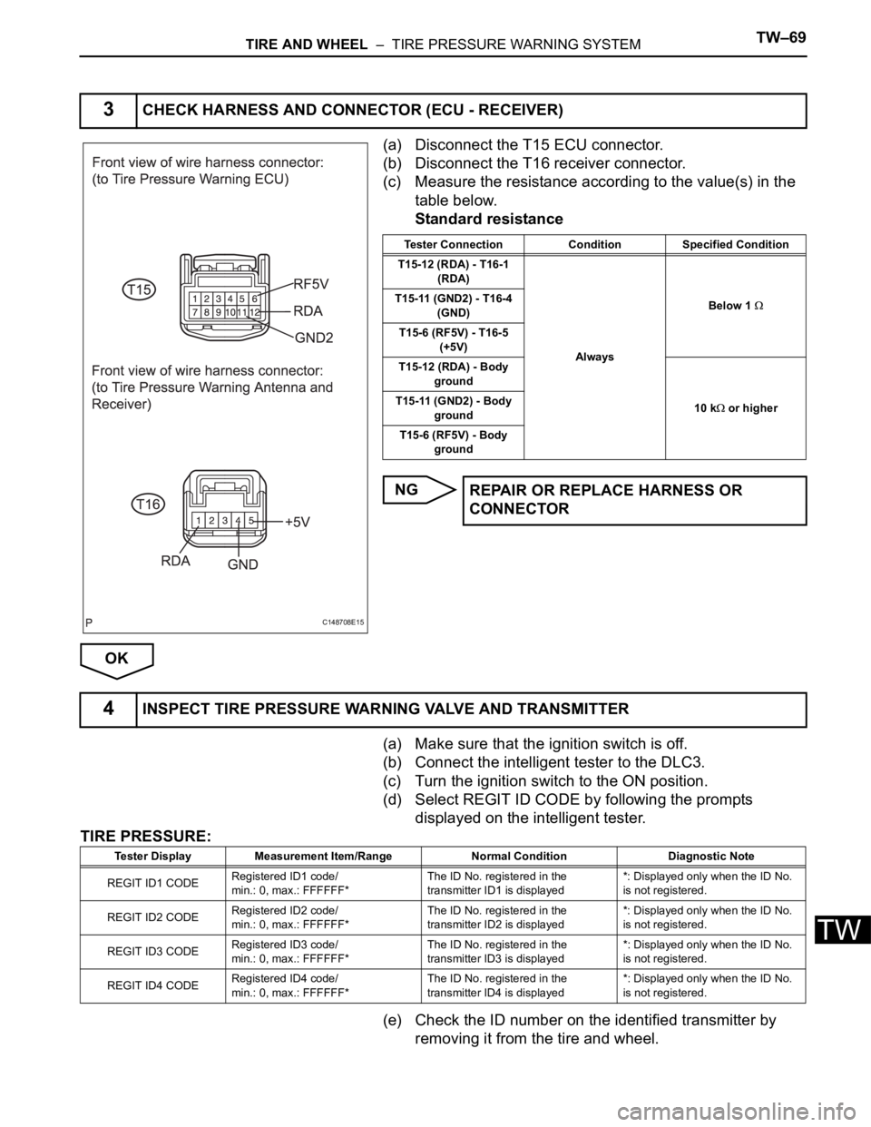
(a) Disconnect the T15 ECU connector.
(b) Disconnect the T16 receiver connector.
(c) Measure the resistance according to the value(s) in the
table below.
Standard resistance
NG
OK
(a) Reconnect the T15 ECU connector.
(b) Turn the ignition switch to the ON position.
(c) Measure the voltage according to the value(s) in the
table below.
Standard voltage
NG
1CHECK HARNESS AND CONNECTOR (ECU - RECEIVER)
C148708E15
Tester Connection Condition Specified Condition
T15-6 (RF5V) - T16-5
(+5V)
AlwaysBelow 1
T15-12 (RDA) - T16-1
(RDA)
T15-11 (GND2) - T16-4
(GND)
T15-6 (RF5V) - Body
ground
10 k
or higher T15-12 (RDA) - Body
ground
T15-11 (GND2) - Body
ground
REPAIR OR REPLACE HARNESS OR
CONNECTOR
2CHECK TIRE PRESSURE WARNING ECU
C148710E06
Tester Connection Switch Condition Specified Condition
T15-6 (RF5V) - T15-11
(GND2)Ignition switch ON 4.5 to 5.5 V
REPLACE TIRE PRESSURE WARNING ECU
(See page TW-87)
Page 2308 of 3000
TW–66TIRE AND WHEEL – TIRE PRESSURE WARNING SYSTEM
TW
DESCRIPTION
Initialization is necessary after replacing any of the ECUs, tires with different tire pressure, or tire pressure
warning valve and transmitter, after rotating the tires or when a new vehicle is delivered.
WIRING DIAGRAM
DTC C2177/77 Initialization not Completed
DTC No. DTC Detection Condition Trouble Area
C2177/77Initialization is not completed after vehicle speed of 5
mph (8 km/h) or more continues for 20 minutes or more
(total).• Tire pressure warning valve and transmitter
• Tire pressure warning ECU
• Tire pressure warning antenna and receiver
• Wire harness or connector
B166325E03
Page 2311 of 3000

TIRE AND WHEEL – TIRE PRESSURE WARNING SYSTEMTW–69
TW
(a) Disconnect the T15 ECU connector.
(b) Disconnect the T16 receiver connector.
(c) Measure the resistance according to the value(s) in the
table below.
Standard resistance
NG
OK
(a) Make sure that the ignition switch is off.
(b) Connect the intelligent tester to the DLC3.
(c) Turn the ignition switch to the ON position.
(d) Select REGIT ID CODE by following the prompts
displayed on the intelligent tester.
TIRE PRESSURE:
(e) Check the ID number on the identified transmitter by
removing it from the tire and wheel.
3CHECK HARNESS AND CONNECTOR (ECU - RECEIVER)
C148708E15
Tester Connection Condition Specified Condition
T15-12 (RDA) - T16-1
(RDA)
AlwaysBelow 1
T15-11 (GND2) - T16-4
(GND)
T15-6 (RF5V) - T16-5
(+5V)
T15-12 (RDA) - Body
ground
10 k
or higher T15-11 (GND2) - Body
ground
T15-6 (RF5V) - Body
ground
REPAIR OR REPLACE HARNESS OR
CONNECTOR
4INSPECT TIRE PRESSURE WARNING VALVE AND TRANSMITTER
Tester Display Measurement Item/Range Normal Condition Diagnostic Note
REGIT ID1 CODERegistered ID1 code/
min.: 0, max.: FFFFFF*The ID No. registered in the
transmitter ID1 is displayed*: Displayed only when the ID No.
is not registered.
REGIT ID2 CODERegistered ID2 code/
min.: 0, max.: FFFFFF*The ID No. registered in the
transmitter ID2 is displayed*: Displayed only when the ID No.
is not registered.
REGIT ID3 CODERegistered ID3 code/
min.: 0, max.: FFFFFF*The ID No. registered in the
transmitter ID3 is displayed*: Displayed only when the ID No.
is not registered.
REGIT ID4 CODERegistered ID4 code/
min.: 0, max.: FFFFFF*The ID No. registered in the
transmitter ID4 is displayed*: Displayed only when the ID No.
is not registered.
Page 2315 of 3000

TIRE AND WHEEL – TIRE PRESSURE WARNING SYSTEMTW–73
TW
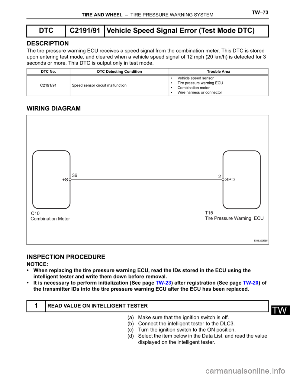
DESCRIPTION
The tire pressure warning ECU receives a speed signal from the combination meter. This DTC is stored
upon entering test mode, and cleared when a vehicle speed signal of 12 mph (20 km/h) is detected for 3
seconds or more. This DTC is output only in test mode.
WIRING DIAGRAM
INSPECTION PROCEDURE
NOTICE:
• When replacing the tire pressure warning ECU, read the IDs stored in the ECU using the
intelligent tester and write them down before removal.
• It is necessary to perform initialization (See page TW-23) after registration (See page TW-20) of
the transmitter IDs into the tire pressure warning ECU after the ECU has been replaced.
(a) Make sure that the ignition switch is off.
(b) Connect the intelligent tester to the DLC3.
(c) Turn the ignition switch to the ON position.
(d) Select the item below in the Data List, and read the value
displayed on the intelligent tester.
DTC C2191/91 Vehicle Speed Signal Error (Test Mode DTC)
DTC No. DTC Detecting Condition Trouble Area
C2191/91 Speed sensor circuit malfunction• Vehicle speed sensor
• Tire pressure warning ECU
• Combination meter
• Wire harness or connector
1READ VALUE ON INTELLIGENT TESTER
E115290E65
Page 2316 of 3000
TW–74TIRE AND WHEEL – TIRE PRESSURE WARNING SYSTEM
TW
HINT:
Enter the following menus: DIAGNOSIS / OBD/MOBD /
METER / DATA LIST.
METER:
(e) Check that the values indicated on the tester and on the
combination meter are the same.
OK:
Vehicle speed indicated on the intelligent tester
indicates the actual speed.
NG
OK
(a) Disconnect the T15 ECU connector.
(b) Disconnect the C10 meter connector.
(c) Measure the resistance according to the value(s) in the
table below.
Standard resistance
NG
OK
Item Normal Condition
VEHICLE SPD Almost same as actual vehicle speed
GO TO METER / GAUGE SYSTEM
2CHECK HARNESS AND CONNECTOR (ECU - COMBINATION METER)
C159184E04
Tester Connection Condition Specified Condition
T15-2 (SPD) - C10-36
(+S)
AlwaysBelow 1
T15-2 (SPD) - Body
ground10 k or higher
REPAIR OR REPLACE HARNESS OR
CONNECTOR
REPLACE TIRE PRESSURE WARNING ECU (See page TW-87)
Page 2318 of 3000

TW–76TIRE AND WHEEL – TIRE PRESSURE WARNING SYSTEM
TW
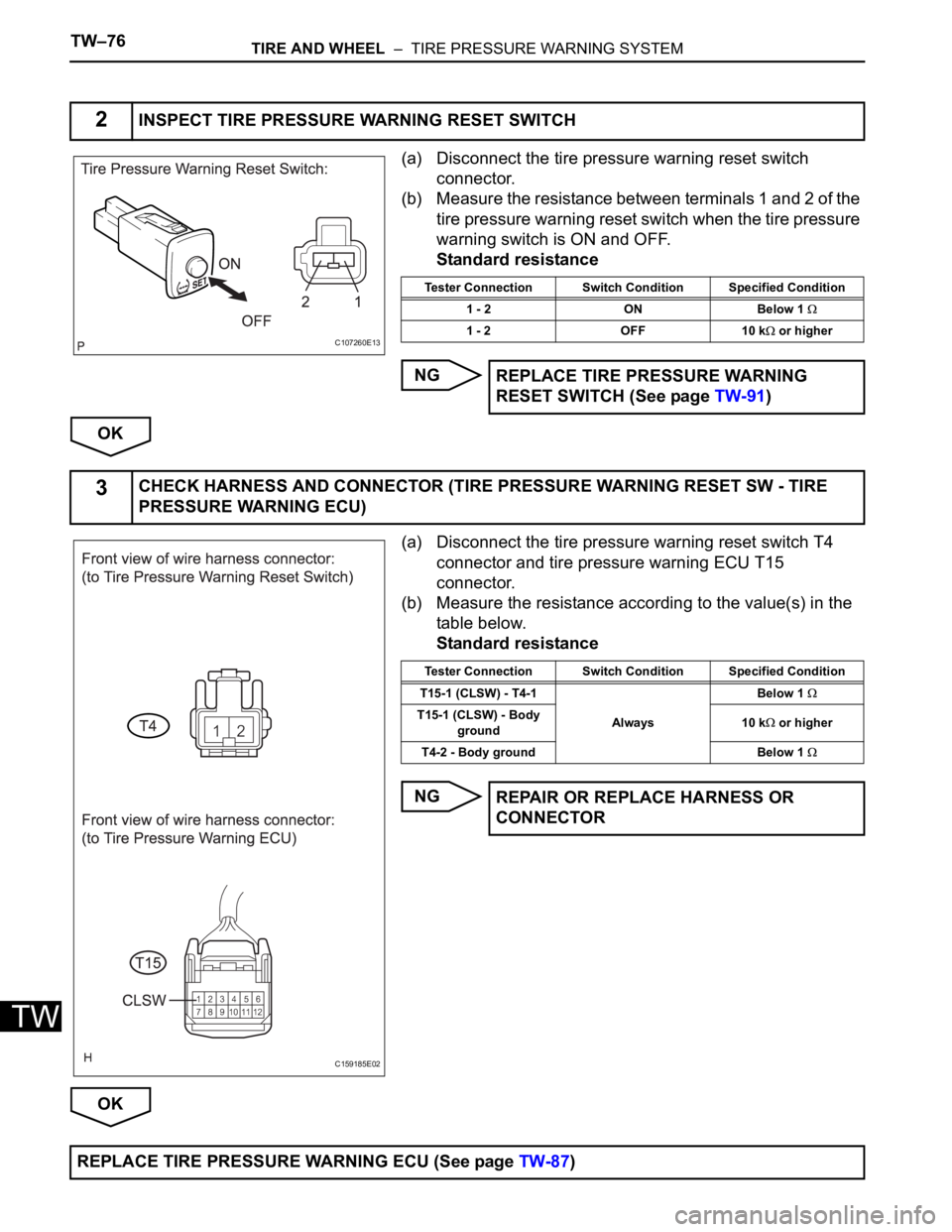
(a) Disconnect the tire pressure warning reset switch
connector.
(b) Measure the resistance between terminals 1 and 2 of the
tire pressure warning reset switch when the tire pressure
warning switch is ON and OFF.
Standard resistance
NG
OK
(a) Disconnect the tire pressure warning reset switch T4
connector and tire pressure warning ECU T15
connector.
(b) Measure the resistance according to the value(s) in the
table below.
Standard resistance
NG
OK
2INSPECT TIRE PRESSURE WARNING RESET SWITCH
C107260E13
Tester Connection Switch Condition Specified Condition
1 - 2 ON Below 1
1 - 2 OFF 10 k or higher
REPLACE TIRE PRESSURE WARNING
RESET SWITCH (See page TW-91)
3CHECK HARNESS AND CONNECTOR (TIRE PRESSURE WARNING RESET SW - TIRE
PRESSURE WARNING ECU)
C159185E02
Tester Connection Switch Condition Specified Condition
T15-1 (CLSW) - T4-1
AlwaysBelow 1
T15-1 (CLSW) - Body
ground10 k or higher
T4-2 - Body ground Below 1
REPAIR OR REPLACE HARNESS OR
CONNECTOR
REPLACE TIRE PRESSURE WARNING ECU (See page TW-87)
Page 2320 of 3000
TW–78TIRE AND WHEEL – TIRE PRESSURE WARNING SYSTEM
TW
(a) Disconnect the C10 combination meter connector.
(b) Disconnect the T15 tire pressure warning ECU
connector.
(c) Measure the resistance according to the value(s) in the
table below.
Standard resistance
NG
OK
(a) Disconnect the connector from the tire pressure warning
ECU.
(b) Turn the ignition switch to the ON position, and check if
the tire pressure warning light illuminates.
Result
B
1CHECK HARNESS AND CONNECTOR (COMBINATION METER - TIRE PRESSURE
WARNING ECU)
C159184E03
Tester Connection Condition Specified Condition
C10-6 (TIRE) - T15-5
(IND)
AlwaysBelow 1
C10-6 (TIRE) - Body
ground10 k or higher
REPAIR OR REPLACE HARNESS OR
CONNECTOR
2INSPECT COMBINATION METER
C148851E05
Result Proceed to
Illuminates A
Does not illuminate B
REPLACE COMBINATION METER (See page
ME-51)
Page 2323 of 3000

TIRE AND WHEEL – TIRE PRESSURE WARNING SYSTEMTW–81
TW
OK
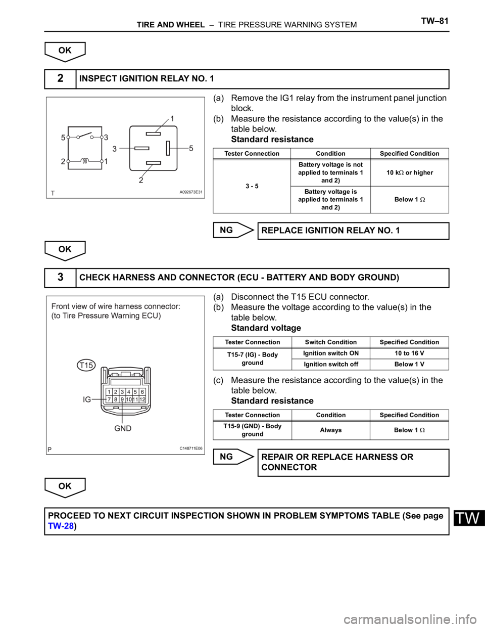
(a) Remove the IG1 relay from the instrument panel junction
block.
(b) Measure the resistance according to the value(s) in the
table below.
Standard resistance
NG
OK
(a) Disconnect the T15 ECU connector.
(b) Measure the voltage according to the value(s) in the
table below.
Standard voltage
(c) Measure the resistance according to the value(s) in the
table below.
Standard resistance
NG
OK
2INSPECT IGNITION RELAY NO. 1
A092673E31
Tester Connection Condition Specified Condition
3 - 5Battery voltage is not
applied to terminals 1
and 2)10 k
or higher
Battery voltage is
applied to terminals 1
and 2)Below 1
REPLACE IGNITION RELAY NO. 1
3CHECK HARNESS AND CONNECTOR (ECU - BATTERY AND BODY GROUND)
C148711E06
Tester Connection Switch Condition Specified Condition
T15-7 (IG) - Body
groundIgnition switch ON 10 to 16 V
Ignition switch off Below 1 V
Tester Connection Condition Specified Condition
T15-9 (GND) - Body
groundAlways Below 1
REPAIR OR REPLACE HARNESS OR
CONNECTOR
PROCEED TO NEXT CIRCUIT INSPECTION SHOWN IN PROBLEM SYMPTOMS TABLE (See page
TW-28)