Page 2525 of 3000
BRAKE CONTROL – VEHICLE STABILITY CONTROL SYSTEMBC–163
BC
(a) Measure the resistance according to the value(s) in the
table below.
Standard resistance
HINT:
If troubleshooting has been carried out according to the
Problem Symptoms Table, refer back to the table and
proceed to the next step (See page BC-79).
NG
OK
8CHECK HARNESS AND CONNECTOR (SKID CONTROL ECU - TRACTION OFF SWITCH)
C159743E01
Tester Connection Condition Specified Condition
S3-43 (CSW) - T5-3 (+) Always Below 1
S3-43 (CSW) - Body
groundAlways 10 k or higher
T5-4 (E) - Body ground Always Below 1
REPAIR OR REPLACE HARNESS OR
CONNECTOR
REPLACE BRAKE ACTUATOR ASSEMBLY
Page 2534 of 3000
BC–172BRAKE CONTROL – VEHICLE STABILITY CONTROL SYSTEM
BC
OK
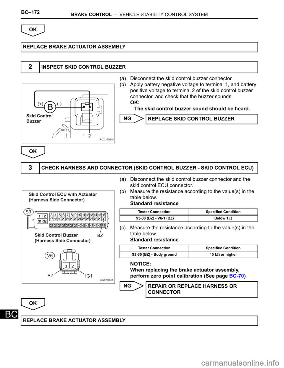
(a) Disconnect the skid control buzzer connector.
(b) Apply battery negative voltage to terminal 1, and battery
positive voltage to terminal 2 of the skid control buzzer
connector, and check that the buzzer sounds.
OK:
The skid control buzzer sound should be heard.
NG
OK
(a) Disconnect the skid control buzzer connector and the
skid control ECU connector.
(b) Measure the resistance according to the value(s) in the
table below.
Standard resistance
(c) Measure the resistance according to the value(s) in the
table below.
Standard resistance
NOTICE:
When replacing the brake actuator assembly,
perform zero point calibration (See page BC-70)
NG
OK REPLACE BRAKE ACTUATOR ASSEMBLY
2INSPECT SKID CONTROL BUZZER
F002192E10
REPLACE SKID CONTROL BUZZER
3CHECK HARNESS AND CONNECTOR (SKID CONTROL BUZZER - SKID CONTROL ECU)
G026280E05
Tester Connection Specified Condition
S3-30 (BZ) - V6-1 (BZ) Below 1
Tester Connection Specified Condition
S3-30 (BZ) - Body ground 10 k
or higher
REPAIR OR REPLACE HARNESS OR
CONNECTOR
REPLACE BRAKE ACTUATOR ASSEMBLY
Page 2539 of 3000
BRAKE CONTROL – VEHICLE STABILITY CONTROL SYSTEMBC–177
BC
DESCRIPTION
In the sensor check mode, a malfunction of the speed sensor that cannot be detected when the vehicle is
stopped is detected while driving.
Transition to the sensor check mode can be performed by connecting terminals TS and CG of the DLC3
and turning the ignition switch from off to the ON position.
WIRING DIAGRAM
INSPECTION PROCEDURE
(a) Turn the ignition switch to the ON position.
(b) Measure the voltage according to the value(s) in the
table below.
Standard voltage
NG
OK
(a) Disconnect the skid control ECU connector.
TS and CG Terminal Circuit
1INSPECT DLC3
F045121E03
E106867E20
Tester Connection Specified Condition
D1-12 (TS) - D1-4 (CG) 10 to 14 V
REPAIR OR REPLACE HARNESS OR
CONNECTOR
2CHECK HARNESS AND CONNECTOR (TS of DLC3 - SKID CONTROL ECU)
Page 2552 of 3000
BRAKE CONTROL – ANTI-LOCK BRAKE SYSTEMBC–23
BC
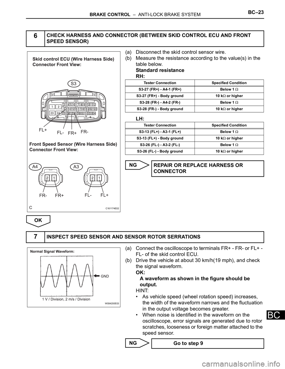
(a) Disconnect the skid control sensor wire.
(b) Measure the resistance according to the value(s) in the
table below.
Standard resistance
RH:
LH:
NG
OK
(a) Connect the oscilloscope to terminals FR+ - FR- or FL+ -
FL- of the skid control ECU.
(b) Drive the vehicle at about 30 km/h(19 mph), and check
the signal waveform.
OK:
A waveform as shown in the figure should be
output.
HINT:
• As vehicle speed (wheel rotation speed) increases,
the width of the waveform narrows and the fluctuation
in the output voltage becomes greater.
• When noise is identified in the waveform on the
oscilloscope, error signals are generated due to rotor
scratches, looseness or foreign matter attached to the
speed sensor.
NG
6CHECK HARNESS AND CONNECTOR (BETWEEN SKID CONTROL ECU AND FRONT
SPEED SENSOR)
C161174E02
Tester Connection Specified Condition
S3-27 (FR+) - A4-1 (FR+) Below 1
S3-27 (FR+) - Body ground 10 k or higher
S3-28 (FR-) - A4-2 (FR-) Below 1
S3-28 (FR-) - Body ground 10 k or higher
Tester Connection Specified Condition
S3-13 (FL+) - A3-1 (FL+) Below 1
S3-13 (FL+) - Body ground 10 k or higher
S3-26 (FL-) - A3-2 (FL-) Below 1
S3-26 (FL-) - Body ground 10 k or higher
REPAIR OR REPLACE HARNESS OR
CONNECTOR
7INSPECT SPEED SENSOR AND SENSOR ROTOR SERRATIONS
W004200E03
Go to step 9
Page 2563 of 3000
BRAKE CONTROL – ANTI-LOCK BRAKE SYSTEMBC–29
BC
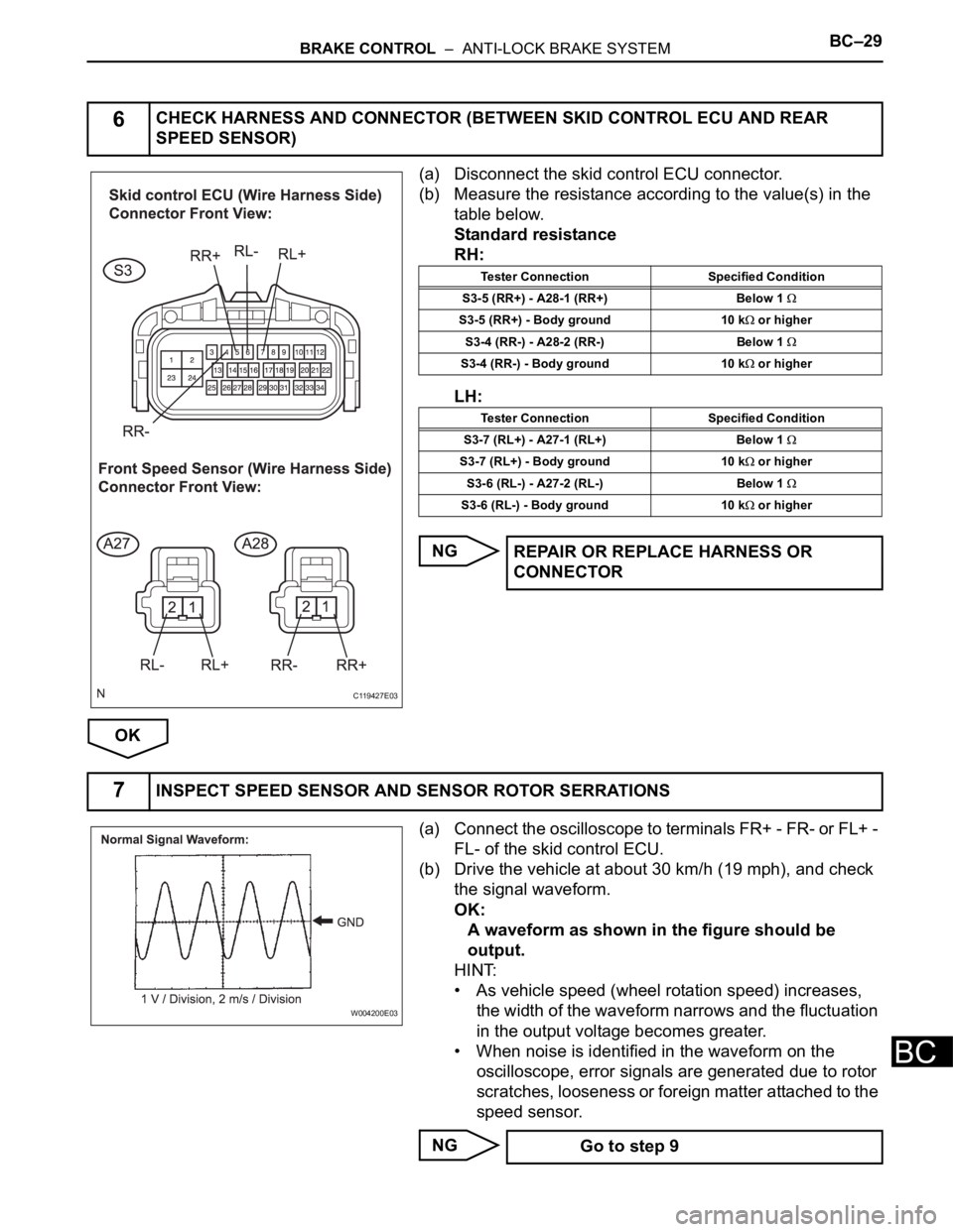
(a) Disconnect the skid control ECU connector.
(b) Measure the resistance according to the value(s) in the
table below.
Standard resistance
RH:
LH:
NG
OK
(a) Connect the oscilloscope to terminals FR+ - FR- or FL+ -
FL- of the skid control ECU.
(b) Drive the vehicle at about 30 km/h (19 mph), and check
the signal waveform.
OK:
A waveform as shown in the figure should be
output.
HINT:
• As vehicle speed (wheel rotation speed) increases,
the width of the waveform narrows and the fluctuation
in the output voltage becomes greater.
• When noise is identified in the waveform on the
oscilloscope, error signals are generated due to rotor
scratches, looseness or foreign matter attached to the
speed sensor.
NG
6CHECK HARNESS AND CONNECTOR (BETWEEN SKID CONTROL ECU AND REAR
SPEED SENSOR)
C119427E03
Tester Connection Specified Condition
S3-5 (RR+) - A28-1 (RR+) Below 1
S3-5 (RR+) - Body ground 10 k or higher
S3-4 (RR-) - A28-2 (RR-) Below 1
S3-4 (RR-) - Body ground 10 k or higher
Tester Connection Specified Condition
S3-7 (RL+) - A27-1 (RL+) Below 1
S3-7 (RL+) - Body ground 10 k or higher
S3-6 (RL-) - A27-2 (RL-) Below 1
S3-6 (RL-) - Body ground 10 k or higher
REPAIR OR REPLACE HARNESS OR
CONNECTOR
7INSPECT SPEED SENSOR AND SENSOR ROTOR SERRATIONS
W004200E03
Go to step 9
Page 2568 of 3000
BC–32BRAKE CONTROL – ANTI-LOCK BRAKE SYSTEM
BC
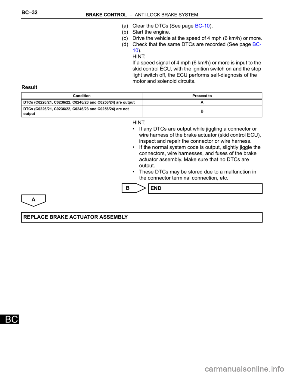
(a) Clear the DTCs (See page BC-10).
(b) Start the engine.
(c) Drive the vehicle at the speed of 4 mph (6 km/h) or more.
(d) Check that the same DTCs are recorded (See page BC-
10).
HINT:
If a speed signal of 4 mph (6 km/h) or more is input to the
skid control ECU, with the ignition switch on and the stop
light switch off, the ECU performs self-diagnosis of the
motor and solenoid circuits.
Result
HINT:
• If any DTCs are output while jiggling a connector or
wire harness of the brake actuator (skid control ECU),
inspect and repair the connector or wire harness.
• If the normal system code is output, slightly jiggle the
connectors, wire harnesses, and fuses of the brake
actuator assembly. Make sure that no DTCs are
output.
• These DTCs may be stored due to a malfunction in
the connector terminal connection, etc.
B
A
Condition Proceed to
DTCs (C0226/21, C0236/22, C0246/23 and C0256/24) are output A
DTCs (C0226/21, C0236/22, C0246/23 and C0256/24) are not
outputB
END
REPLACE BRAKE ACTUATOR ASSEMBLY
Page 2572 of 3000
BC–34BRAKE CONTROL – ANTI-LOCK BRAKE SYSTEM
BC
NG
OK
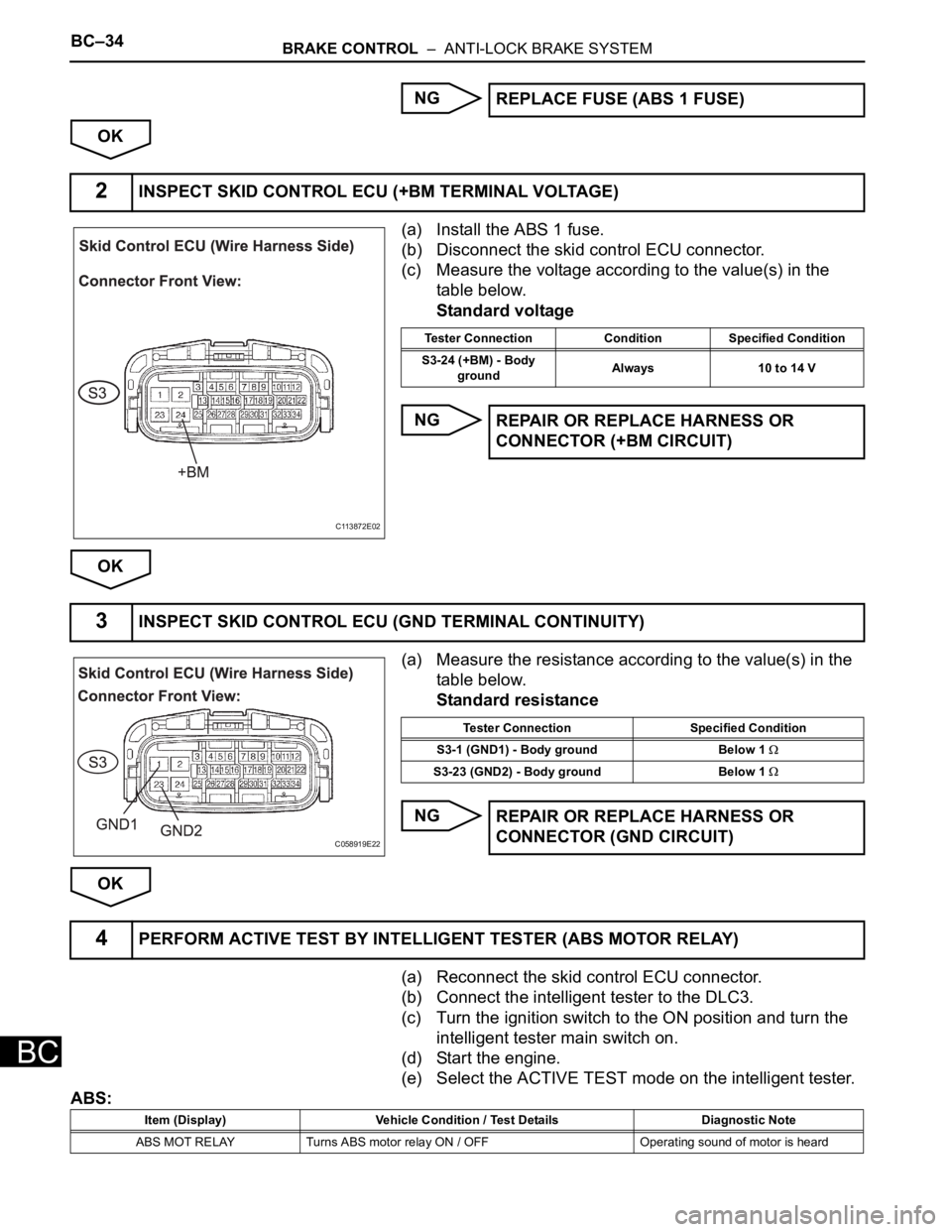
(a) Install the ABS 1 fuse.
(b) Disconnect the skid control ECU connector.
(c) Measure the voltage according to the value(s) in the
table below.
Standard voltage
NG
OK
(a) Measure the resistance according to the value(s) in the
table below.
Standard resistance
NG
OK
(a) Reconnect the skid control ECU connector.
(b) Connect the intelligent tester to the DLC3.
(c) Turn the ignition switch to the ON position and turn the
intelligent tester main switch on.
(d) Start the engine.
(e) Select the ACTIVE TEST mode on the intelligent tester.
ABS:REPLACE FUSE (ABS 1 FUSE)
2INSPECT SKID CONTROL ECU (+BM TERMINAL VOLTAGE)
C113872E02
Tester Connection Condition Specified Condition
S3-24 (+BM) - Body
groundAlways 10 to 14 V
REPAIR OR REPLACE HARNESS OR
CONNECTOR (+BM CIRCUIT)
3INSPECT SKID CONTROL ECU (GND TERMINAL CONTINUITY)
C058919E22
Tester Connection Specified Condition
S3-1 (GND1) - Body ground Below 1
S3-23 (GND2) - Body ground Below 1
REPAIR OR REPLACE HARNESS OR
CONNECTOR (GND CIRCUIT)
4PERFORM ACTIVE TEST BY INTELLIGENT TESTER (ABS MOTOR RELAY)
Item (Display) Vehicle Condition / Test Details Diagnostic Note
ABS MOT RELAY Turns ABS motor relay ON / OFF Operating sound of motor is heard
Page 2573 of 3000
BRAKE CONTROL – ANTI-LOCK BRAKE SYSTEMBC–35
BC
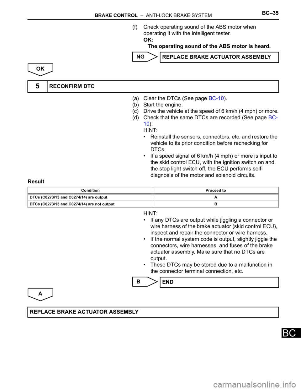
(f) Check operating sound of the ABS motor when
operating it with the intelligent tester.
OK:
The operating sound of the ABS motor is heard.
NG
OK
(a) Clear the DTCs (See page BC-10).
(b) Start the engine.
(c) Drive the vehicle at the speed of 6 km/h (4 mph) or more.
(d) Check that the same DTCs are recorded (See page BC-
10).
HINT:
• Reinstall the sensors, connectors, etc. and restore the
vehicle to its prior condition before rechecking for
DTCs.
• If a speed signal of 6 km/h (4 mph) or more is input to
the skid control ECU, with the ignition switch on and
the stop light switch off, the ECU performs self-
diagnosis of the motor and solenoid circuits.
Result
HINT:
• If any DTCs are output while jiggling a connector or
wire harness of the brake actuator (skid control ECU),
inspect and repair the connector or wire harness.
• If the normal system code is output, slightly jiggle the
connectors, wire harnesses, and fuses of the brake
actuator assembly. Make sure that no DTCs are
output.
• These DTCs may be stored due to a malfunction in
the connector terminal connection, etc.
B
AREPLACE BRAKE ACTUATOR ASSEMBLY
5RECONFIRM DTC
Condition Proceed to
DTCs (C0273/13 and C0274/14) are output A
DTCs (C0273/13 and C0274/14) are not output B
END
REPLACE BRAKE ACTUATOR ASSEMBLY