Page 2577 of 3000
BRAKE CONTROL – ANTI-LOCK BRAKE SYSTEMBC–37
BC
(a) Install the ABS 2 fuse.
(b) Disconnect the skid control ECU connector.
(c) Measure the voltage according to the value(s) in the
table below.
Standard voltage
NG
OK
(a) Measure the resistance according to the value(s) in the
table below.
Standard resistance
NG
OK
(a) Clear the DTCs (See page BC-10).
(b) Start the engine.
(c) Drive the vehicle at the speed of 6 km/h (4 mph) or more.
(d) Check that the same DTCs are recorded (See page BC-
10).
HINT:
• Reinstall the sensors, connectors, etc. and restore the
vehicle to its prior condition before rechecking for
DTCs.
• If a speed signal of 6 km/h (4 mph) or more is input to
the skid control ECU, with the ignition switch on and
the stop light switch off, the ECU performs self-
diagnosis of the motor and solenoid circuits.
Result
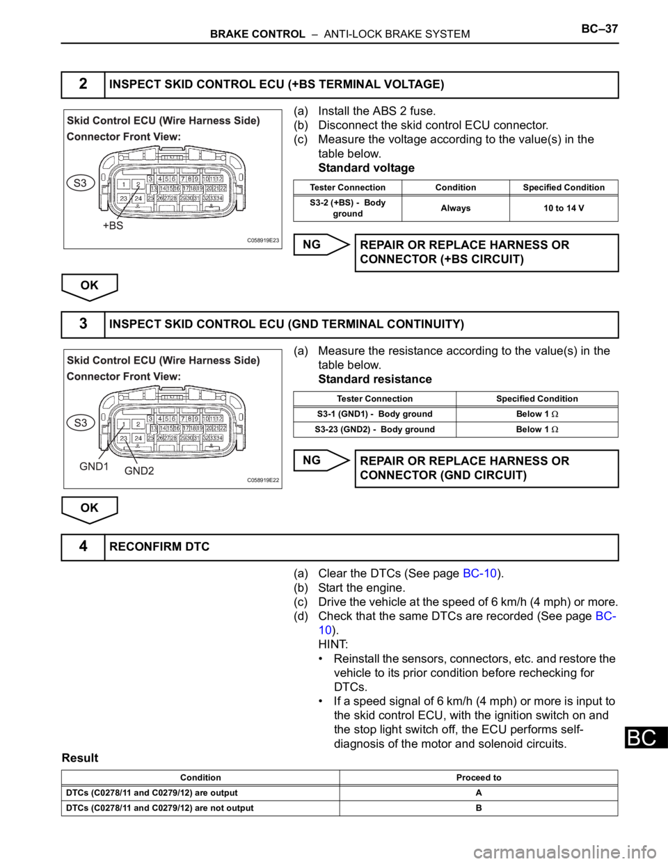
2INSPECT SKID CONTROL ECU (+BS TERMINAL VOLTAGE)
C058919E23
Tester Connection Condition Specified Condition
S3-2 (+BS) - Body
groundAlways 10 to 14 V
REPAIR OR REPLACE HARNESS OR
CONNECTOR (+BS CIRCUIT)
3INSPECT SKID CONTROL ECU (GND TERMINAL CONTINUITY)
C058919E22
Tester Connection Specified Condition
S3-1 (GND1) - Body ground Below 1
S3-23 (GND2) - Body ground Below 1
REPAIR OR REPLACE HARNESS OR
CONNECTOR (GND CIRCUIT)
4RECONFIRM DTC
Condition Proceed to
DTCs (C0278/11 and C0279/12) are output A
DTCs (C0278/11 and C0279/12) are not output B
Page 2578 of 3000
BC–38BRAKE CONTROL – ANTI-LOCK BRAKE SYSTEM
BC
HINT:
• If any DTCs are output while jiggling a connector or
wire harness of the brake actuator (skid control ECU),
inspect and repair the connector or wire harness.
• If the normal system code is output, slightly jiggle the
connectors, wire harnesses, and fuses of the brake
actuator assembly. Make sure that no DTCs are
output.
• These DTCs may be memorized due to a malfunction
in the connector terminal connection, etc.
B
AEND
REPLACE BRAKE ACTUATOR ASSEMBLY
Page 2583 of 3000
BC–40BRAKE CONTROL – ANTI-LOCK BRAKE SYSTEM
BC
(a) Check the battery voltage.
Standard voltage:
11 to 14 V
NG
OK
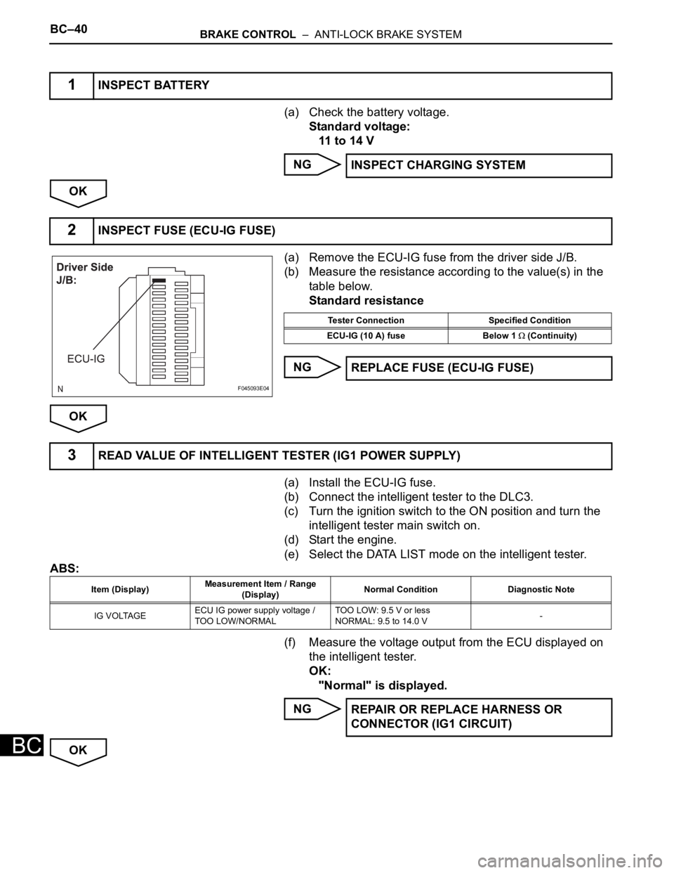
(a) Remove the ECU-IG fuse from the driver side J/B.
(b) Measure the resistance according to the value(s) in the
table below.
Standard resistance
NG
OK
(a) Install the ECU-IG fuse.
(b) Connect the intelligent tester to the DLC3.
(c) Turn the ignition switch to the ON position and turn the
intelligent tester main switch on.
(d) Start the engine.
(e) Select the DATA LIST mode on the intelligent tester.
ABS:
(f) Measure the voltage output from the ECU displayed on
the intelligent tester.
OK:
"Normal" is displayed.
NG
OK
1INSPECT BATTERY
INSPECT CHARGING SYSTEM
2INSPECT FUSE (ECU-IG FUSE)
F045093E04
Tester Connection Specified Condition
ECU-IG (10 A) fuse Below 1
(Continuity)
REPLACE FUSE (ECU-IG FUSE)
3READ VALUE OF INTELLIGENT TESTER (IG1 POWER SUPPLY)
Item (Display)Measurement Item / Range
(Display)Normal Condition Diagnostic Note
IG VOLTAGEECU IG power supply voltage /
TOO LOW/NORMALTOO LOW: 9.5 V or less
NORMAL: 9.5 to 14.0 V-
REPAIR OR REPLACE HARNESS OR
CONNECTOR (IG1 CIRCUIT)
Page 2584 of 3000
BRAKE CONTROL – ANTI-LOCK BRAKE SYSTEMBC–41
BC
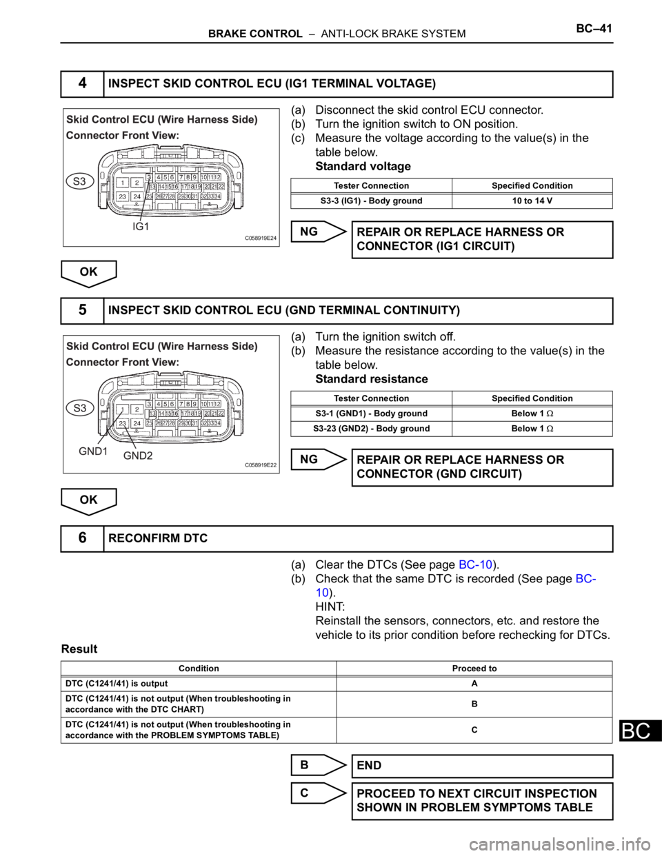
(a) Disconnect the skid control ECU connector.
(b) Turn the ignition switch to ON position.
(c) Measure the voltage according to the value(s) in the
table below.
Standard voltage
NG
OK
(a) Turn the ignition switch off.
(b) Measure the resistance according to the value(s) in the
table below.
Standard resistance
NG
OK
(a) Clear the DTCs (See page BC-10).
(b) Check that the same DTC is recorded (See page BC-
10).
HINT:
Reinstall the sensors, connectors, etc. and restore the
vehicle to its prior condition before rechecking for DTCs.
Result
B
C
4INSPECT SKID CONTROL ECU (IG1 TERMINAL VOLTAGE)
C058919E24
Tester Connection Specified Condition
S3-3 (IG1) - Body ground 10 to 14 V
REPAIR OR REPLACE HARNESS OR
CONNECTOR (IG1 CIRCUIT)
5INSPECT SKID CONTROL ECU (GND TERMINAL CONTINUITY)
C058919E22
Tester Connection Specified Condition
S3-1 (GND1) - Body ground Below 1
S3-23 (GND2) - Body ground Below 1
REPAIR OR REPLACE HARNESS OR
CONNECTOR (GND CIRCUIT)
6RECONFIRM DTC
Condition Proceed to
DTC (C1241/41) is outputA
DTC (C1241/41) is not output (When troubleshooting in
accordance with the DTC CHART)B
DTC (C1241/41) is not output (When troubleshooting in
accordance with the PROBLEM SYMPTOMS TABLE)C
END
PROCEED TO NEXT CIRCUIT INSPECTION
SHOWN IN PROBLEM SYMPTOMS TABLE
Page 2675 of 3000
STEERING COLUMN – STEERING COLUMN ASSEMBLYSR–11
SR
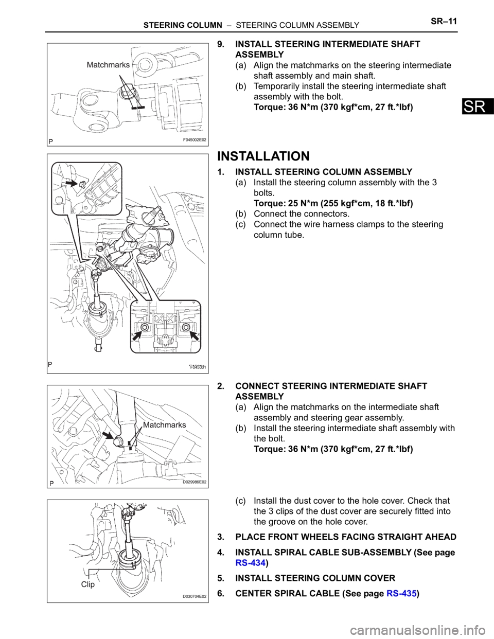
9. INSTALL STEERING INTERMEDIATE SHAFT
ASSEMBLY
(a) Align the matchmarks on the steering intermediate
shaft assembly and main shaft.
(b) Temporarily install the steering intermediate shaft
assembly with the bolt.
Torque: 36 N*m (370 kgf*cm, 27 ft.*lbf)
INSTALLATION
1. INSTALL STEERING COLUMN ASSEMBLY
(a) Install the steering column assembly with the 3
bolts.
Torque: 25 N*m (255 kgf*cm, 18 ft.*lbf)
(b) Connect the connectors.
(c) Connect the wire harness clamps to the steering
column tube.
2. CONNECT STEERING INTERMEDIATE SHAFT
ASSEMBLY
(a) Align the matchmarks on the intermediate shaft
assembly and steering gear assembly.
(b) Install the steering intermediate shaft assembly with
the bolt.
Torque: 36 N*m (370 kgf*cm, 27 ft.*lbf)
(c) Install the dust cover to the hole cover. Check that
the 3 clips of the dust cover are securely fitted into
the groove on the hole cover.
3. PLACE FRONT WHEELS FACING STRAIGHT AHEAD
4. INSTALL SPIRAL CABLE SUB-ASSEMBLY (See page
RS-434)
5. INSTALL STEERING COLUMN COVER
6. CENTER SPIRAL CABLE (See page RS-435)
F045002E02
F045001
D029986E02
D030704E02
Page 2684 of 3000
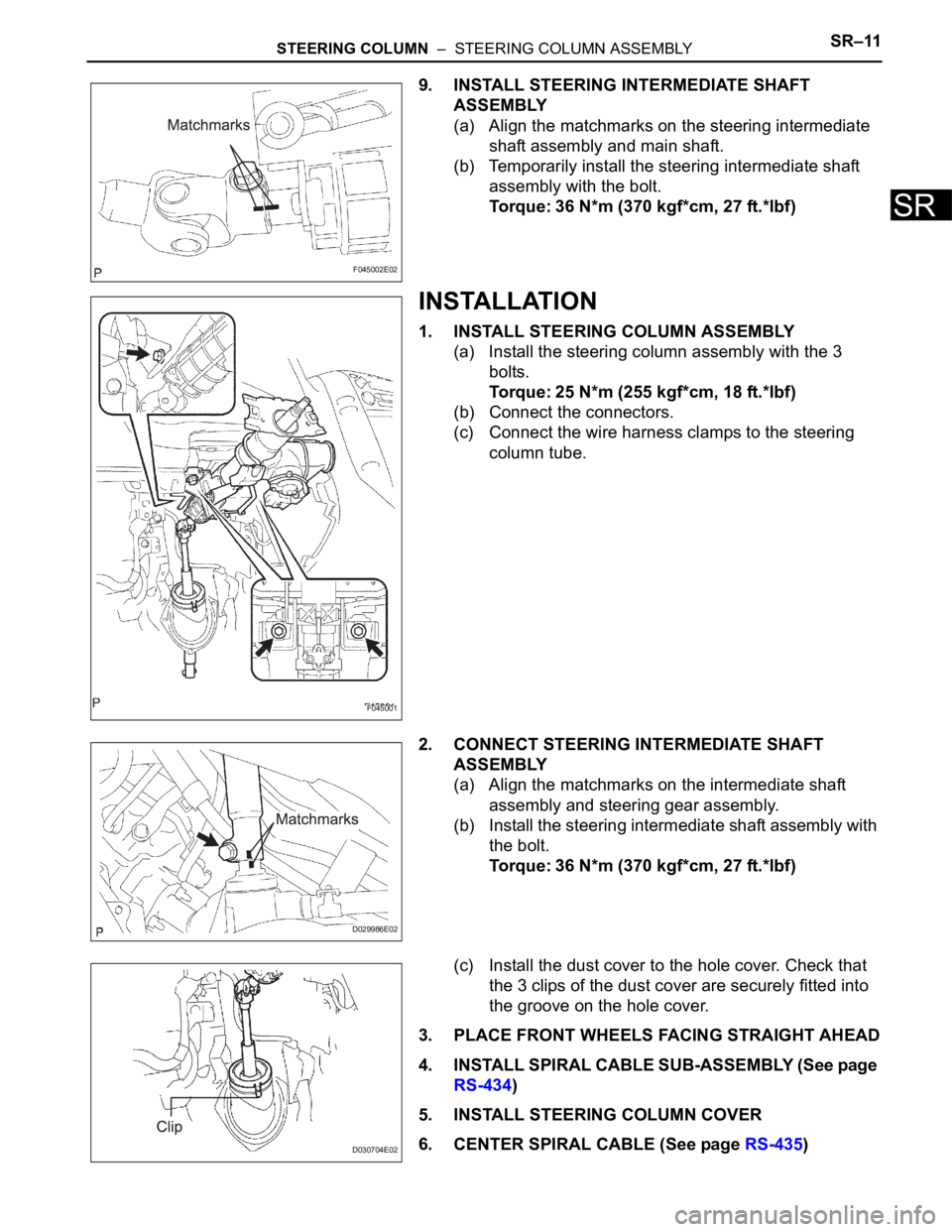
STEERING COLUMN – STEERING COLUMN ASSEMBLYSR–11
SR
9. INSTALL STEERING INTERMEDIATE SHAFT
ASSEMBLY
(a) Align the matchmarks on the steering intermediate
shaft assembly and main shaft.
(b) Temporarily install the steering intermediate shaft
assembly with the bolt.
Torque: 36 N*m (370 kgf*cm, 27 ft.*lbf)
INSTALLATION
1. INSTALL STEERING COLUMN ASSEMBLY
(a) Install the steering column assembly with the 3
bolts.
Torque: 25 N*m (255 kgf*cm, 18 ft.*lbf)
(b) Connect the connectors.
(c) Connect the wire harness clamps to the steering
column tube.
2. CONNECT STEERING INTERMEDIATE SHAFT
ASSEMBLY
(a) Align the matchmarks on the intermediate shaft
assembly and steering gear assembly.
(b) Install the steering intermediate shaft assembly with
the bolt.
Torque: 36 N*m (370 kgf*cm, 27 ft.*lbf)
(c) Install the dust cover to the hole cover. Check that
the 3 clips of the dust cover are securely fitted into
the groove on the hole cover.
3. PLACE FRONT WHEELS FACING STRAIGHT AHEAD
4. INSTALL SPIRAL CABLE SUB-ASSEMBLY (See page
RS-434)
5. INSTALL STEERING COLUMN COVER
6. CENTER SPIRAL CABLE (See page RS-435)
F045002E02
F045001
D029986E02
D030704E02
Page 2767 of 3000
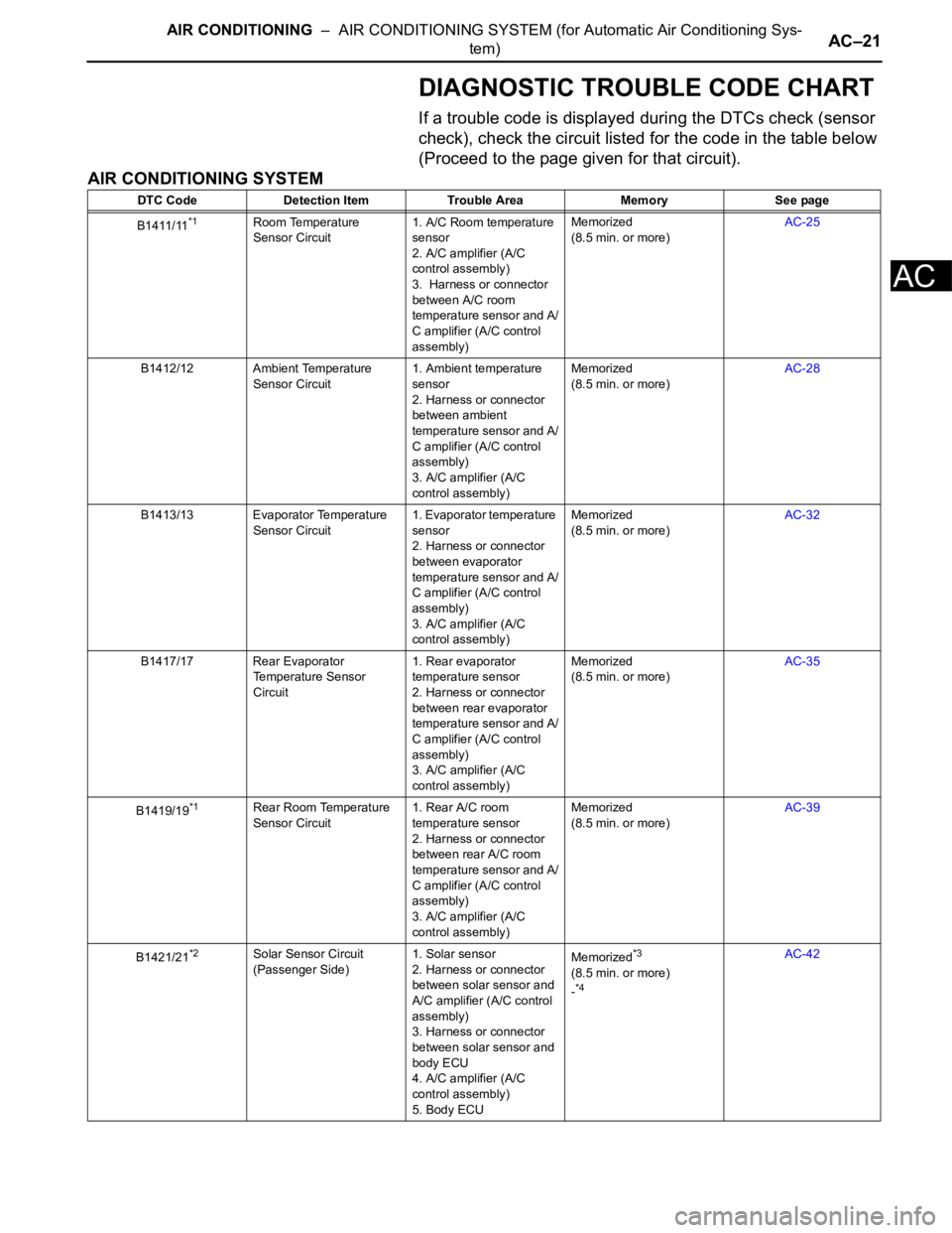
AIR CONDITIONING – AIR CONDITIONING SYSTEM (for Automatic Air Conditioning Sys-
tem)AC–21
AC
DIAGNOSTIC TROUBLE CODE CHART
If a trouble code is displayed during the DTCs check (sensor
check), check the circuit listed for the code in the table below
(Proceed to the page given for that circuit).
AIR CONDITIONING SYSTEM
DTC Code Detection Item Trouble Area Memory See page
B1411/11
*1Room Temperature
Sensor Circuit1. A/C Room temperature
sensor
2. A/C amplifier (A/C
control assembly)
3. Harness or connector
between A/C room
temperature sensor and A/
C amplifier (A/C control
assembly)Memorized
(8.5 min. or more)AC-25
B1412/12 Ambient Temperature
Sensor Circuit1. Ambient temperature
sensor
2. Harness or connector
between ambient
temperature sensor and A/
C amplifier (A/C control
assembly)
3. A/C amplifier (A/C
control assembly)Memorized
(8.5 min. or more)AC-28
B1413/13 Evaporator Temperature
Sensor Circuit1. Evaporator temperature
sensor
2. Harness or connector
between evaporator
temperature sensor and A/
C amplifier (A/C control
assembly)
3. A/C amplifier (A/C
control assembly)Memorized
(8.5 min. or more)AC-32
B1417/17 Rear Evaporator
Temperature Sensor
Circuit1. Rear evaporator
temperature sensor
2. Harness or connector
between rear evaporator
temperature sensor and A/
C amplifier (A/C control
assembly)
3. A/C amplifier (A/C
control assembly)Memorized
(8.5 min. or more)AC-35
B1419/19
*1Rear Room Temperature
Sensor Circuit1. Rear A/C room
temperature sensor
2. Harness or connector
between rear A/C room
temperature sensor and A/
C amplifier (A/C control
assembly)
3. A/C amplifier (A/C
control assembly)Memorized
(8.5 min. or more)AC-39
B1421/21
*2Solar Sensor Circuit
(Passenger Side)1. Solar sensor
2. Harness or connector
between solar sensor and
A/C amplifier (A/C control
assembly)
3. Harness or connector
between solar sensor and
body ECU
4. A/C amplifier (A/C
control assembly)
5. Body ECUMemorized*3
(8.5 min. or more)
-*4
AC-42
Page 2768 of 3000
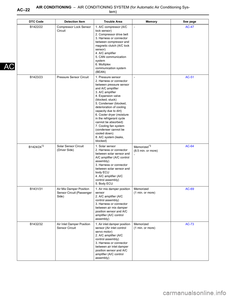
AC–22AIR CONDITIONING – AIR CONDITIONING SYSTEM (for Automatic Air Conditioning Sys-
tem)
AC
B1422/22 Compressor Lock Sensor
Circuit1. A/C compressor (A/C
lock sensor)
2. Compressor drive belt
3. Harness or connector
between compressor and
magnetic clutch (A/C lock
sensor)
4. A/C amplifier
5. CAN communication
system
6. Multiplex
communication system
(BEAN)-AC-47
B1423/23 Pressure Sensor Circuit 1. Pressure sensor
2. Harness or connector
between pressure sensor
and A/C amplifier
3. A/C amplifier
4. Expansion valve
(blocked, stuck)
5. Condenser (blocked,
deterioration of cooling
capacity due to dirt)
6. Cooler dryer (moisture
in the refrigerant cycle
cannot be absorbed)
7. Cooling fan system
(condenser cannot be
cooled down)
8. A/C system (leaks,
blocked)-AC-51
B1424/24
*2Solar Sensor Circuit
(Driver Side)1. Solar sensor
2. Harness or connector
between solar sensor and
A/C amplifier (A/C control
assembly)
3. Harness or connector
between solar sensor and
body ECU
4. A/C amplifier (A/C
control assembly)
5. Body ECUMemorized*3
(8.5 min. or more)
-AC-64
B1431/31 Air Mix Damper Position
Sensor Circuit (Passenger
Side)1. Air mix damper position
sensor
2. A/C amplifier (A/C
control assembly)
3. Harness or connector
between air mix damper
position sensor and A/C
amplifier (A/C control
assembly)Memorized
(1 min. or more)AC-69
B1432/32 Air Inlet Damper Position
Sensor Circuit1. Air inlet damper position
sensor (Air inlet control
servo motor)
2. A/C amplifier (A/C
control assembly)
3. Harness or connector
between air inlet damper
position sensor and A/C
amplifier (A/C control
assembly)Memorized
(1 min. or more)AC-73 DTC Code Detection Item Trouble Area Memory See page