Page 660 of 1449
MPI -On-vehicle Service13A-128
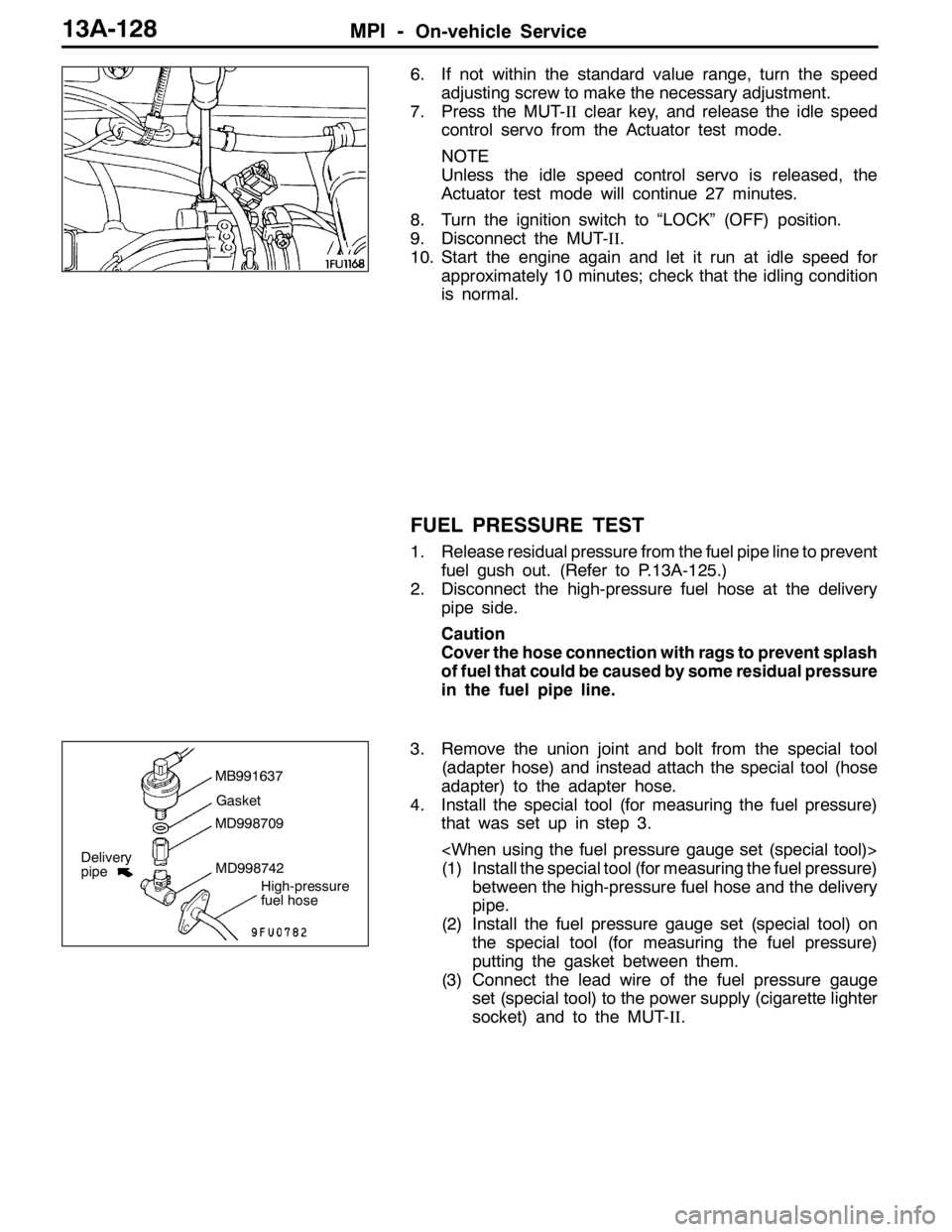
6. If not within the standard value range, turn the speed
adjusting screw to make the necessary adjustment.
7. Press the MUT-IIclear key, and release the idle speed
control servo from the Actuator test mode.
NOTE
Unless the idle speed control servo is released, the
Actuator test mode will continue 27 minutes.
8. Turn the ignition switch to “LOCK” (OFF) position.
9. Disconnect the MUT-II.
10. Start the engine again and let it run at idle speed for
approximately 10 minutes; check that the idling condition
is normal.
FUEL PRESSURE TEST
1. Release residual pressure from the fuel pipe line to prevent
fuel gush out. (Refer to P.13A-125.)
2. Disconnect the high-pressure fuel hose at the delivery
pipe side.
Caution
Cover the hose connection with rags to prevent splash
of fuel that could be caused by some residual pressure
in the fuel pipe line.
3. Remove the union joint and bolt from the special tool
(adapter hose) and instead attach the special tool (hose
adapter) to the adapter hose.
4. Install the special tool (for measuring the fuel pressure)
that was set up in step 3.
(1) Install the special tool (for measuring the fuel pressure)
between the high-pressure fuel hose and the delivery
pipe.
(2) Install the fuel pressure gauge set (special tool) on
the special tool (for measuring the fuel pressure)
putting the gasket between them.
(3) Connect the lead wire of the fuel pressure gauge
set (special tool) to the power supply (cigarette lighter
socket) and to the MUT-II.
MB991637
Gasket
MD998709
MD998742
High-pressure
fuel hose
Delivery
pipe
Page 661 of 1449
MPI -On-vehicle Service13A-129
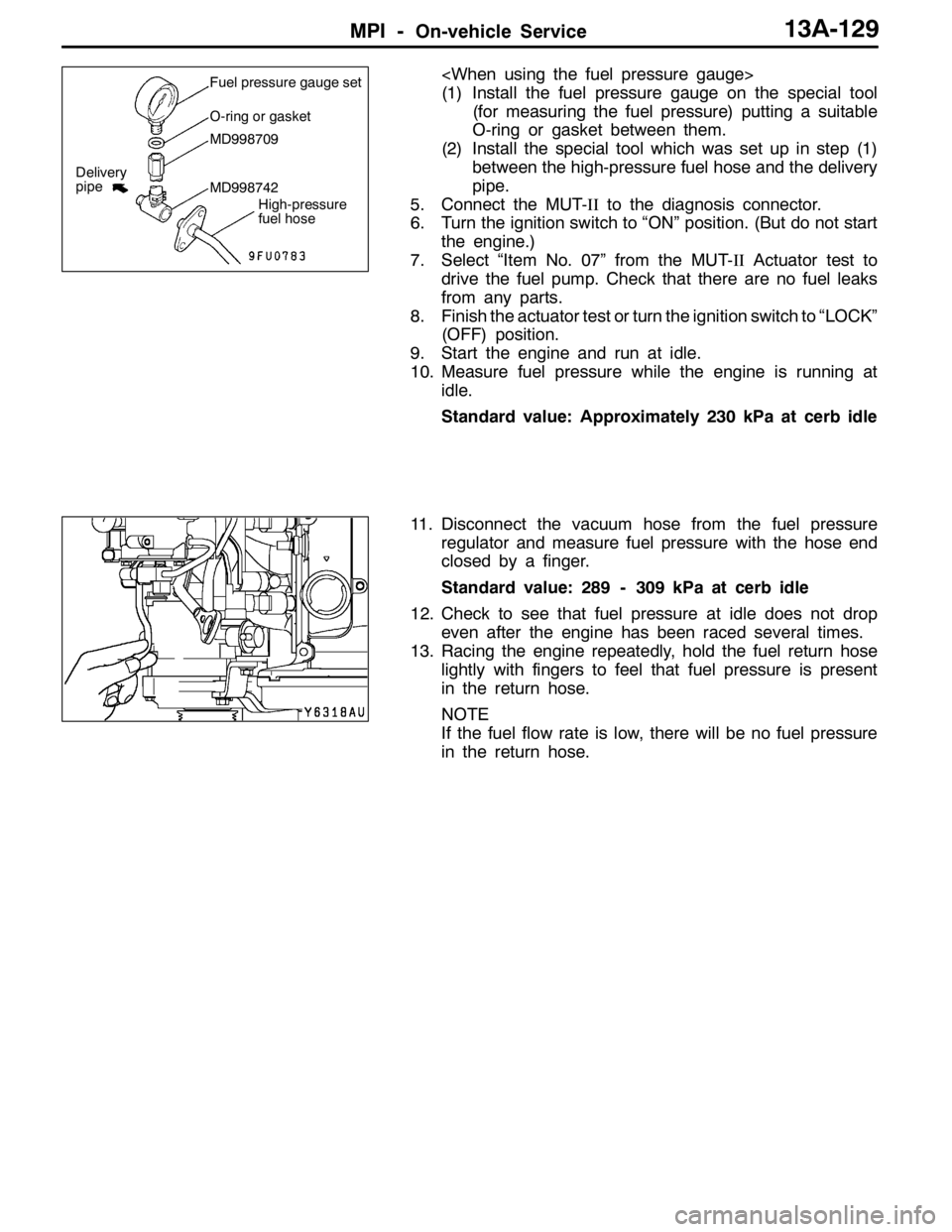
(1) Install the fuel pressure gauge on the special tool
(for measuring the fuel pressure) putting a suitable
O-ring or gasket between them.
(2) Install the special tool which was set up in step (1)
between the high-pressure fuel hose and the delivery
pipe.
5. Connect the MUT-IIto the diagnosis connector.
6. Turn the ignition switch to “ON” position. (But do not start
the engine.)
7. Select “Item No. 07” from the MUT-IIActuator test to
drive the fuel pump. Check that there are no fuel leaks
from any parts.
8. Finish the actuator test or turn the ignition switch to “LOCK”
(OFF) position.
9. Start the engine and run at idle.
10. Measure fuel pressure while the engine is running at
idle.
Standard value: Approximately 230 kPa at cerb idle
11. Disconnect the vacuum hose from the fuel pressure
regulator and measure fuel pressure with the hose end
closed by a finger.
Standard value: 289 - 309 kPa at cerb idle
12. Check to see that fuel pressure at idle does not drop
even after the engine has been raced several times.
13. Racing the engine repeatedly, hold the fuel return hose
lightly with fingers to feel that fuel pressure is present
in the return hose.
NOTE
If the fuel flow rate is low, there will be no fuel pressure
in the return hose.Fuel pressure gauge set
O-ring or gasket
MD998709
MD998742
High-pressure
fuel hose
Delivery
pipe
Page 671 of 1449

MPI -On-vehicle Service13A-139
Checking the Coil Resistance
1. Disconnect the idle speed control servo connector.
2. Measure the resistance between terminal No. 2 and either
terminal No. 1 or terminal No. 3 of the connector at the
idle speed control servo side.
Standard value: 28 - 33Ω(at 20_C)
3. Measure the resistance between terminal No. 5 and either
terminal No. 6 or terminal No. 4 of the connector at the
idle speed control servo side.
Standard value: 28 - 33Ω(at 20_C)
Operation Check
1. Remove the throttle body.
2. Remove the stepper motor.
3. Connect the special tool (test harness: MB991709) to
the idle speed control servo connector.
4. Connect the positive (+) terminal of a power supply
(approximately 6 V) to the terminals No. 2 and No. 5.
5. With the idle speed control servo as shown in the
illustration, connect the negative ( - ) terminal of the power
supply to each clip as described in the following steps,
and check whether or not a vibrating feeling (a feeling
of very slight vibration of the stepper motor) is generated
as a result of the activation of the stepper motor.
(1) Connect the negative ( - ) terminal of the power supply
to the terminals No. 1 and No. 4.
(2) Connect the negative ( - ) terminal of the power supply
to the terminals No. 3 and No. 4.
(3) Connect the negative ( - ) terminal of the power supply
to the terminals No. 3 and No. 6.
(4) Connect the negative ( - ) terminal of the power supply
to the terminals No. 1 and No. 6
(5) Connect the negative ( - ) terminal of the power supply
to the terminals No. 1 and No. 4.
(6) Repeat the tests in sequence from (5) to (1).
6. If, as a result of these tests, vibration is detected, the
stepper motor can be considered to be normal.
Page 682 of 1449
FUEL SUPPLY - General Information/On-vehicle Service13B-2
GENERAL INFORMATION
DThe steel fuel tank is located under the floor of the rear seats to provide increased safety and increase
the amount of luggage compartment space.
DThe fuel tank has been equipped with a valve assembly which incorporates a fuel cut-off valve to
prevent fuel from leaking out in the event of a collision for adjusting the pressure inside the fuel
tank.
DThe fuel pump module contains a fuel pump, fuel filter, and fuel pressure regulator.
ON-VEHICLE SERVICE
FUEL PUMP AND GAUGE ASSEMBLY (FUEL
PUMP)
1. FUEL PUMP OPERATION CHECK
Refer to GROUP 13A - On-vehicle service
2. FUEL PUMP REPLACEMENT
(1) Remove the rear seat cushion assembly.
(Refer to GROUP 52A.)
(2) Remove the service hole cover.
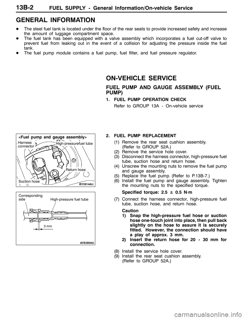
(3) Disconnect the harness connector, high-pressure fuel
tube, suction hose and return hose.
(4) Unscrew the mounting nuts to remove the fuel pump
and gauge assembly.
(5) Replace the fuel pump. (Refer to P.13B-7.)
(6) Install the fuel pump and gauge assembly. Tighten
the mounting nuts to the specified torque.
Specified torque: 2.5± 0.5 N·m
(7) Connect the harness connector, high-pressure fuel
tube, suction hose, and return hose.
Caution
1) Snap the high-pressure fuel hose or suction
hose one-touch joint into place, then pull back
slightly on the hose to assure it is securely
fitted. However, the connection should have
a play of approx. 3 mm.
2) Insert the return hose for 20 - 30 mm for
connection.
(8) Install the service hole cover.
(9) Install the rear seat cushion assembly.
(Refer to GROUP 52A.)
Harness
connectorHigh-pressurefuel tube
Suction hose
Return hose
3mm
Corresponding
sideHigh-pressure fuel tube
Page 683 of 1449
FUEL SUPPLY - On-vehicle Service/Fuel tank13B-3
FUEL PUMP AND GAUGE ASSEMBLY, PIPE
AND GAUGE ASSEMBLY (FUEL GAUGE UNIT)
1. Remove the rear seat cushion assembly.
(Refer to GROUP 52A.)
2. Remove the service hole cover.
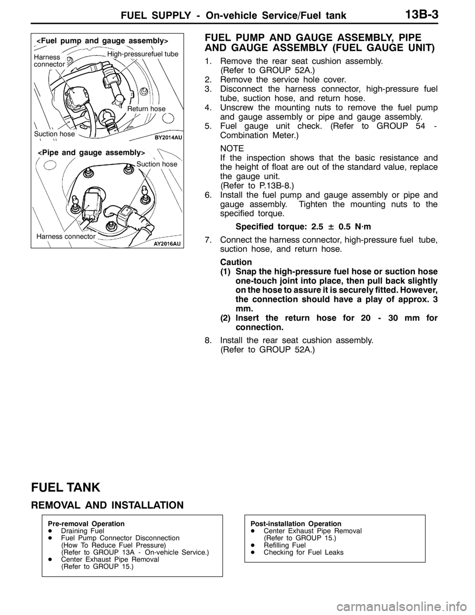
3. Disconnect the harness connector, high-pressure fuel
tube, suction hose, and return hose.
4. Unscrew the mounting nuts to remove the fuel pump
and gauge assembly or pipe and gauge assembly.
5. Fuel gauge unit check. (Refer to GROUP 54 -
Combination Meter.)
NOTE
If the inspection shows that the basic resistance and
the height of float are out of the standard value, replace
the gauge unit.
(Refer to P.13B-8.)
6. Install the fuel pump and gauge assembly or pipe and
gauge assembly. Tighten the mounting nuts to the
specified torque.
Specified torque: 2.5± 0.5 N·m
7. Connect the harness connector, high-pressure fuel tube,
suction hose, and return hose.
Caution
(1) Snap the high-pressure fuel hose or suction hose
one-touch joint into place, then pull back slightly
on the hose to assure it is securely fitted. However,
the connection should have a play of approx. 3
mm.
(2) Insert the return hose for 20 - 30 mm for
connection.
8. Install the rear seat cushion assembly.
(Refer to GROUP 52A.)
FUEL TANK
REMOVAL AND INSTALLATION
Pre-removal Operation
DDraining Fuel
DFuel Pump Connector Disconnection
(How To Reduce Fuel Pressure)
(Refer to GROUP 13A - On-vehicle Service.)
DCenter Exhaust Pipe Removal
(Refer to GROUP 15.)Post-installation Operation
DCenter Exhaust Pipe Removal
(Refer to GROUP 15.)
DRefilling Fuel
DChecking for Fuel Leaks
High-pressurefuel tubeHarness
connector
Suction hose
Return hose
Suction hose
Harness connector
Page 686 of 1449
FUEL SUPPLY - Fuel Tank13B-6
INSTALLATION SERVICE POINT
"AAHIGH-PRESSURE FUEL HOSE/SUCTION HOSE
INSTALLATION
Caution
Snap the high-pressure fuel hose or suction hose
one-touch joint into place, then pull back slightly on the
hose to assure it is securely fitted. However, the
connection should have a play of approx. 3 mm.
"BAFUEL TANK RETURN HOSE INSTALLATION
Caution
Insert the return hose for 20 - 30 mm for connection.
3mm
Corresponding
sideHigh-pressure fuel tube
Page 729 of 1449
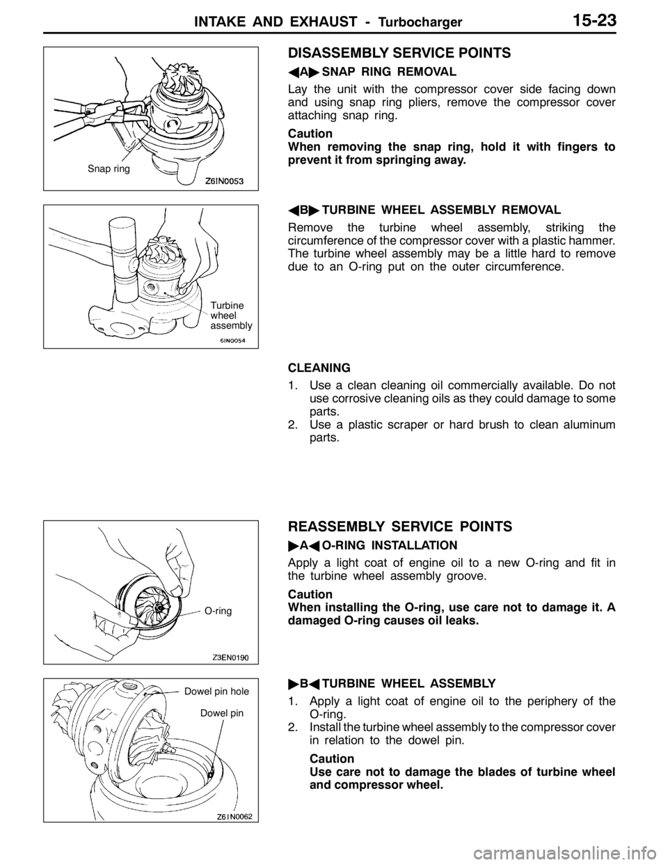
INTAKE AND EXHAUST -Turbocharger15-23
DISASSEMBLY SERVICE POINTS
AA"SNAP RING REMOVAL
Lay the unit with the compressor cover side facing down
and using snap ring pliers, remove the compressor cover
attaching snap ring.
Caution
When removing the snap ring, hold it with fingers to
prevent it from springing away.
AB"TURBINE WHEEL ASSEMBLY REMOVAL
Remove the turbine wheel assembly, striking the
circumference of the compressor cover with a plastic hammer.
The turbine wheel assembly may be a little hard to remove
due to an O-ring put on the outer circumference.
CLEANING
1. Use a clean cleaning oil commercially available. Do not
use corrosive cleaning oils as they could damage to some
parts.
2. Use a plastic scraper or hard brush to clean aluminum
parts.
REASSEMBLY SERVICE POINTS
"AAO-RING INSTALLATION
Apply a light coat of engine oil to a new O-ring and fit in
the turbine wheel assembly groove.
Caution
When installing the O-ring, use care not to damage it. A
damaged O-ring causes oil leaks.
"BATURBINE WHEEL ASSEMBLY
1. Apply a light coat of engine oil to the periphery of the
O-ring.
2. Install the turbine wheel assembly to the compressor cover
in relation to the dowel pin.
Caution
Use care not to damage the blades of turbine wheel
and compressor wheel.
Snap ring
Turbine
wheel
assembly
O-ring
Dowel pin
Dowel pin hole
Page 731 of 1449
INTAKE AND EXHAUST -Turbocharger15-25
COMPRESSOR COVER
Check the compressor cover for traces of contact with the
compressor wheel and other damage.
TURBINE WHEEL ASSEMBLY
1. Check the turbine and compressor wheel blades for bend,
burr, damage, corrosion and traces of contact on the
back side and replace if defective.
2. Check the oil passage of the turbine wheel assembly
for deposit and clogging.
3. In the case of water cooled type, check also the water
passage for deposit and clogging.
4. Check the turbine wheel and compressor wheel for light
and smooth turning.
Oil passage
Turbine wheel
Water passageCompressor
wheel