Page 1116 of 1449

STEERING -General Information37A-2
GENERAL INFORMATION
The system has been equipped with the MOMO
leather 3-spoke-type steering wheel with built-in
SRS airbag.
The steering column is equipped with tilt steering
mechanism.
The power steering is an integral rack and piniontype that combines the steering gear and linkage
into one light-weight and compact assembly.
The steering system uses a vane oil pump with
a fluid flow control system, so that steering effort
varies with engine speed.
ItemLancer EVOLUTION-
Steering wheelTypeMOMO 3-spoke typeg
Outside diameter mm380 ,
365
Maximum number of turns2.1
Steering columnColumn mechanismTilt steering
Power steering typeIntegral type
Oil pumpTypeVariable capacity type (vane pump)pp
Basic discharge amount cm3/rev.9.6
Relief pressure MPa8.3 - 9.0
Reservoir typeSeparate type
Pressure switchEquipped
Steering gear and linkageTypeRack and pinionggg
Stroke ratio (Rack stroke/Steering wheel
Maximum turning radius)68.61
Rack stroke mm146
Steering angleInner wheel32°gg
Outer wheel (for reference)27°
Power steering fluidSpecified lubricantsAutomatic transmission fluid DEXRON IIg
Quantity LApproximately 1.0
Page 1121 of 1449

STEERING -On-vehicle Service37A-7
ON-VEHICLE SERVICE
STEERING WHEEL FREE PLAY CHECK
1. With engine running (hydraulic operation), set front wheels
straight ahead.
2. Measure the play on steering wheel circumference before
wheels start to move when slightly moving steering wheel
in both directions.
Limit: 30 mm or less
3. When play exceeds the limit, check for play on steering
shaft connection and steering linkage. Correct or replace.
4. If the free play still exceeds the limit value, set steering
wheel straight ahead with engine stopped. Load 5 N
towards steering wheel circumference and check play.
Standard value: 0 - 10 mm
5. If the play exceeds the standard value, remove steering
gear box and check total pinion torque. (Refer to
P.37A-17.)
STEERING ANGLE CHECK
1. Locate front wheels on turning radius gauge and measure
steering angle.
Standard value:
Inner wheel31_45’±1_30’
Outer wheel27_15’
2. When the angle is not within the standard value, the
toe-in is probably incorrect. Adjust the toe-in.
Standard value: 0±2mm
Adjust the toe-in by undoing the clip and lock nut, and
turning the left and right tie rod turnbuckles by the same
amount (in opposite directions).
3. Recheck the steering angle.
TIE ROD END BALL JOINT TURNING TORQUE
CHECK
1. Disconnect tie rod and knuckle with special tool.
Caution
(1) Loosen the nut of the special tool, but do not
remove it. If it is removed, the ball joint thread
may be damaged.
(2) Tie the special tool with a cord so as not to fall
off.
Clip
Lock nut
Cord
Ball jointNutMB990635,
MB991113 or
MB991406
Page 1136 of 1449

STEERING - Power Steering Gear Box and Linkage37A-22
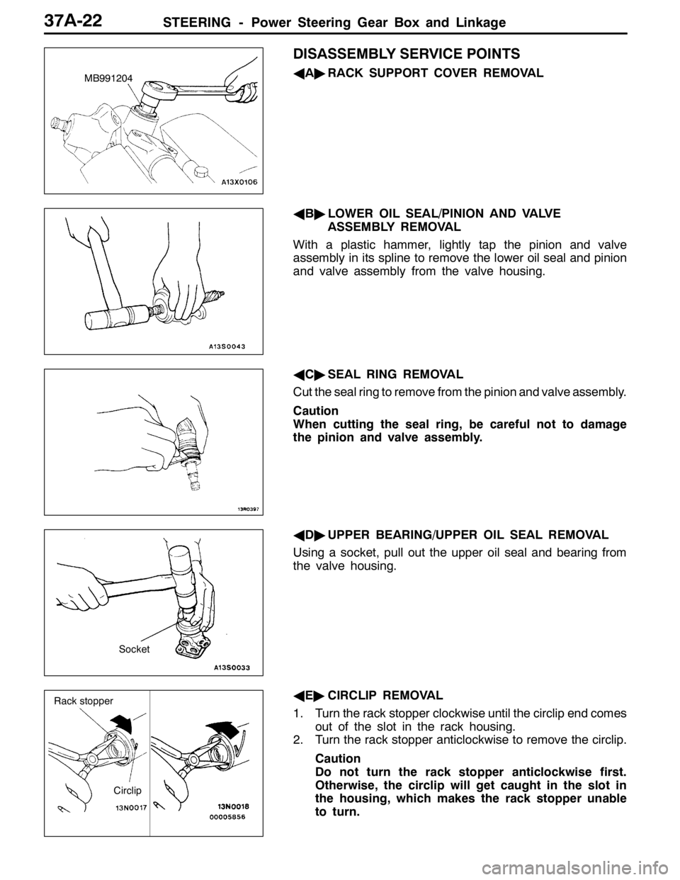
DISASSEMBLY SERVICE POINTS
AA"RACK SUPPORT COVER REMOVAL
AB"LOWER OIL SEAL/PINION AND VALVE
ASSEMBLY REMOVAL
With a plastic hammer, lightly tap the pinion and valve
assembly in its spline to remove the lower oil seal and pinion
and valve assembly from the valve housing.
AC"SEAL RING REMOVAL
Cut the seal ring to remove from the pinion and valve assembly.
Caution
When cutting the seal ring, be careful not to damage
the pinion and valve assembly.
AD"UPPER BEARING/UPPER OIL SEAL REMOVAL
Using a socket, pull out the upper oil seal and bearing from
the valve housing.
AE"CIRCLIP REMOVAL
1. Turn the rack stopper clockwise until the circlip end comes
out of the slot in the rack housing.
2. Turn the rack stopper anticlockwise to remove the circlip.
Caution
Do not turn the rack stopper anticlockwise first.
Otherwise, the circlip will get caught in the slot in
the housing, which makes the rack stopper unable
to turn.MB991204
Socket
Circlip
Rack stopper
Page 1144 of 1449
STEERING - Power Steering Oil Pump/Power Steering Oil Hoses37A-30
"BAPRESSURE HOSE ASSEMBLY/SUCTION HOSE
REMOVAL
Install the pressure hose assembly and suction hose as
illustrated.
DISASSEMBLY AND REASSEMBLY
21±3 N·m
3
4
2 1
39±5 N·m
: Automatic transmission fluid DEXRONII
NOTE
Disassembly steps
1. Suction connector
2. O-ring3. Connector
4. Gasket
POWER STEERING OIL HOSES
REMOVAL AND INSTALLATION
Caution
1. Before removing the clock spring, always see GROUP 52B - Caution for Service and Air Bag
Module Clock Spring
2. If the vehicle is equipped with the Brembo disc brake, during maintenance, take care not to
contact the parts or tools to the caliper, because the paint of caliper will be scratched.
3. On the tightening section indicated in the mark (*), lightly tighten the nut first, and then finally
tighten it with the engine weight applied on the body.
Suction hose
Pressure hose
assembly
Marking
Notch
Page 1158 of 1449

BODY -Window Glass42-10
HANDLING OF AUTO WINDOW SEALER
Keep the sealant in a cool place, not exposed to the direct
rays of the sun. Do not place any heavy article on the sealant
nor press it, otherwise it will become deformed. Avoid storing
the sealant for more than 6 months, because it will lose its
sealing effect.
BODY PINCH-WELD FLANGE SERVICING
Before servicing the body pinch-weld flange, remove old
adhesive completely. If the flange requires painting, bake
it after painting is completed.
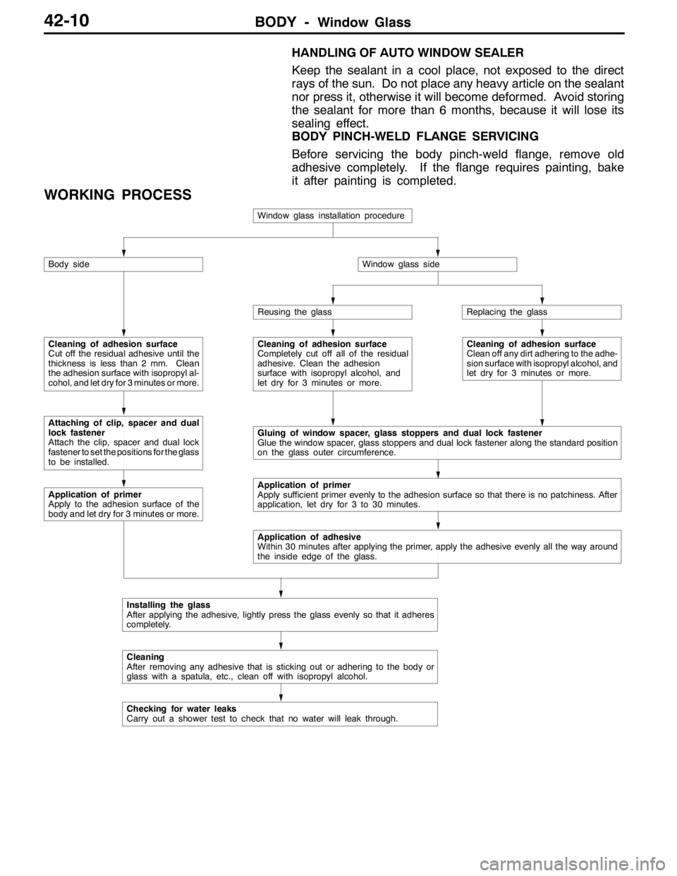
WORKING PROCESS
Window glass installation procedure
Body side
Cleaning of adhesion surface
Cut off the residual adhesive until the
thickness is less than 2 mm. Clean
the adhesion surface with isopropyl al-
cohol, and let dry for 3 minutes or more.
Attaching of clip, spacer and dual
lock fastener
Attach the clip, spacer and dual lock
fastener to set the positions for the glass
to be installed.
Application of primer
Apply to the adhesion surface of the
body and let dry for 3 minutes or more.
Window glass side
Reusing the glassReplacing the glass
Cleaning of adhesion surface
Completely cut off all of the residual
adhesive. Clean the adhesion
surface with isopropyl alcohol, and
let dry for 3 minutes or more.Cleaning of adhesion surface
Clean off any dirt adhering to the adhe-
sion surface with isopropyl alcohol, and
let dry for 3 minutes or more.
Gluing of window spacer, glass stoppers and dual lock fastener
Glue the window spacer, glass stoppers and dual lock fastener along the standard position
on the glass outer circumference.
Application of primer
Apply sufficient primer evenly to the adhesion surface so that there is no patchiness. After
application, let dry for 3 to 30 minutes.
Application of adhesive
Within 30 minutes after applying the primer, apply the adhesive evenly all the way around
the inside edge of the glass.
Installing the glass
After applying the adhesive, lightly press the glass evenly so that it adheres
completely.
Cleaning
After removing any adhesive that is sticking out or adhering to the body or
glass with a spatula, etc., clean off with isopropyl alcohol.
Checking for water leaks
Carry out a shower test to check that no water will leak through.
Page 1163 of 1449

BODY -Window Glass42-15
6. Install the windshield molding.
7. Within thirty minutes after the primer application, fill a
sealant gun with the adhesive, and then apply the
adhesive evenly around the windshield.
NOTE
Cut the tip of the sealant gun nozzle into a V shape
to simplify adhesive application.
8. After applying adhesive, align the mating marks on the
windshield and the body, and then lightly press the
windshield evenly so that it adheres completely.
9. After removing any adhesive that is sticking out or adhering
to the windshield or body with spatula, etc., clean with
isopropyl alcohol. Install the windshield molding before
the adhesive sets. After the windshield is installed, wait
until the adhesive sets.
10. Adhere the windshield to the body, and install the roof
drip molding (Refer to GROUP 51.) promptly before the
adhesive sets.
11. After adhering the windshield to the body, wait 30 minutes
or more, and then test for water leakage.
Caution
(1) Move the vehicle carefully.
(2) When testing for water leakage, do not pinch the
end of the hose to spray the water.
10 mm
15 mm
Page 1169 of 1449

BODY -Doors42-21
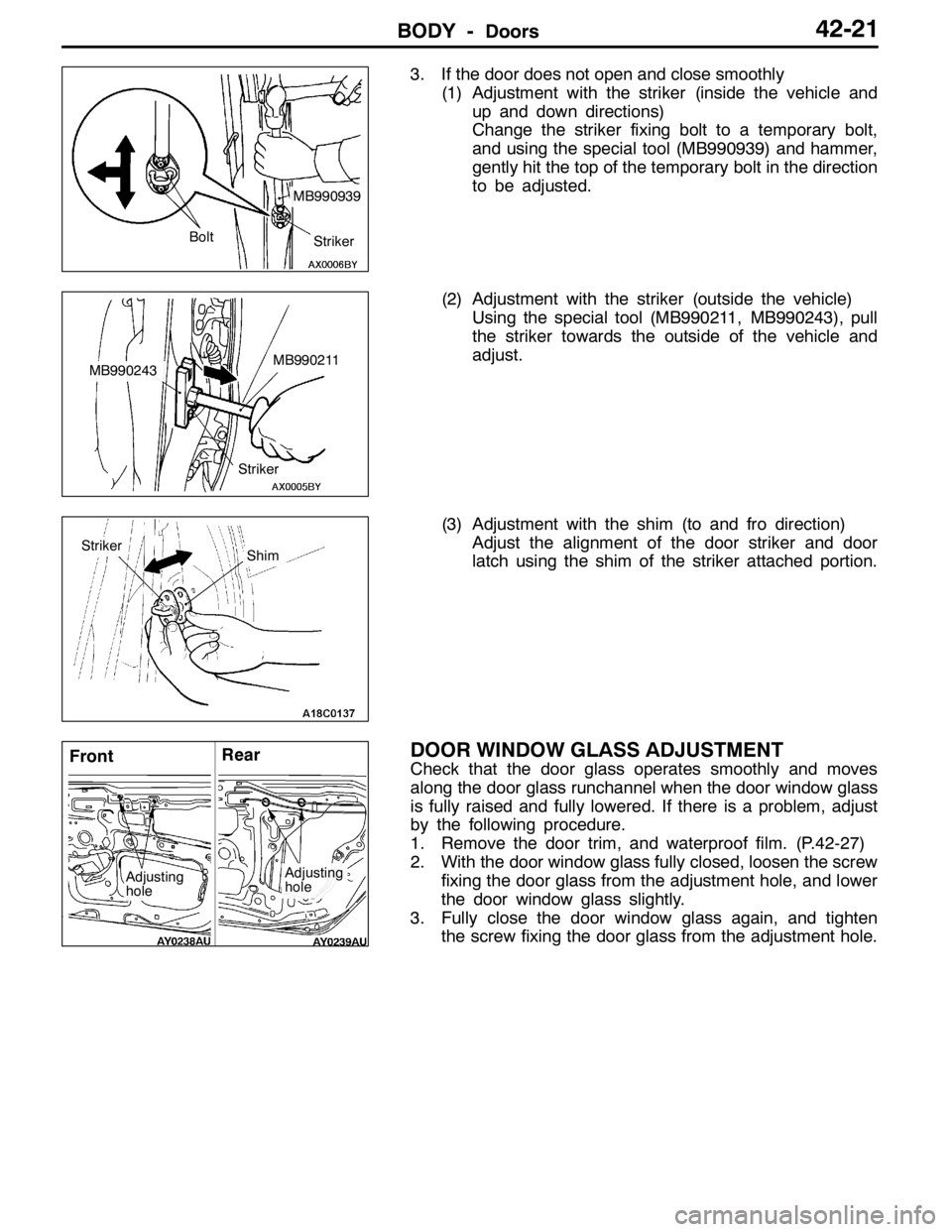
3. If the door does not open and close smoothly
(1) Adjustment with the striker (inside the vehicle and
up and down directions)
Change the striker fixing bolt to a temporary bolt,
and using the special tool (MB990939) and hammer,
gently hit the top of the temporary bolt in the direction
to be adjusted.
(2) Adjustment with the striker (outside the vehicle)
Using the special tool (MB990211, MB990243), pull
the striker towards the outside of the vehicle and
adjust.
(3) Adjustment with the shim (to and fro direction)
Adjust the alignment of the door striker and door
latch using the shim of the striker attached portion.
DOOR WINDOW GLASS ADJUSTMENT
Check that the door glass operates smoothly and moves
along the door glass runchannel when the door window glass
is fully raised and fully lowered. If there is a problem, adjust
by the following procedure.
1. Remove the door trim, and waterproof film. (P.42-27)
2. With the door window glass fully closed, loosen the screw
fixing the door glass from the adjustment hole, and lower
the door window glass slightly.
3. Fully close the door window glass again, and tighten
the screw fixing the door glass from the adjustment hole.
MB990939
Striker Bolt
MB990211MB990243
Striker
StrikerShim
FrontRear
Adjusting
holeAdjusting
hole
Page 1170 of 1449

BODY -Doors42-22
ADJUSTMENTS AND REPLACEMENT DURING
POWER WINDOW MALFUNCTION
If the window glass does not rise but automatically descends,
adjust and replace the window glass as follows:
1. Remove the door trim and waterproof film. (P.42-27)
2. Remove the window regulator assembly from the door
window glass, and raise and lower the window glass with
your hand and check the operating force.
Remarks Insert a cushion, etc. to prevent damage of
the glass if it accidentally drops.
3. If the door window glass does not rise and descend
smoothly, perform the following check and repair.
DCheck the installation condition of the runchannel.
DStraighten twist in the door sash.
DCheck the installation condition of the lower sash
or the center sash.
NOTE
The lower sash cannot normally be adjusted, but it may
be possible to adjust the sash span slightly within the
range allowed by manufacturing tolerances by pushing
the lower sash outwards while re-installing it.
4. If repair or adjustment is not possible, replace the door
assembly.
POWER WINDOW SAFETY MECHANISM
CHECK
1. Set a wood piece of about 10 mm thick as shown in
the figure, and raise the window glass.
2. Check that the window glass descends by about 150
mm when it catches the wood piece. If it does not, perform
troubleshooting. (Refer to GROUP 54B.)
POWER WINDOW TIMER FUNCTION CHECK
9Close the door and turn the ignition switch in the OFF position,
and then check the power window operates for 30 seconds.
If it does not, perform troubleshooting.(Refer to GROUP 54B.)
Runchannel
Door
sash
Lower sash