2007 MITSUBISHI LANCER EVOLUTION light
[x] Cancel search: lightPage 734 of 1449

ENGINE ELECTRICAL -Charging System16-2
CHARGING SYSTEM
GENERAL INFORMATION
The charging system uses the alternator output
to keep the battery charged at a constant level
under various electrical loads.
OPERATION
Rotation of the excited field coil generates AC voltage in
the stator.
This alternating current is rectified through diodes to DC
voltage having a waveform shown in the illustration at left.
The average output voltage fluctuates slightly with the
alternator load condition.
When the ignition switch is turned on, current flows
in the field coil and initial excitation of the field
coil occurs.
When the stator coil begins to generate power after
the engine is started, the field coil is excited by
the output current of the stator coil.
The alternator output voltage rises as the field
current increases and it falls as the field current
decreases. When the battery voltage (alternator
S terminal voltage) reaches a regulated voltageof approximately 14.4 V, the field current is cut
off. When the battery voltage drops below the
regulated voltage, the voltage regulator regulates
the output voltage to a constant level by controlling
the field current.
In addition, when the field current is constant, the
alternator output voltage rises as the engine speed
increases.
SYSTEM DIAGRAM
Stator coil
Field coil
Voltage
regulatorEngine-ECU
Charging
warning lampIgnition
switchBattery B
G
L
FRS
Voltage
Time
Approximately
14.4 V
Page 737 of 1449

ENGINE ELECTRICAL -Charging System16-5
(6) Reconnect the negative battery cable.
(7) Connect a tachometer or the MUT-II.
(Refer to GROUP 11 - On-vehicle Service.)
(8) Leave the hood open.
(9) Start the engine.
(10)With the engine running at 2,500 r/min, turn
the headlamps and other lamps on and off
to adjust the alternator load so that the value
displayed on the ammeter is slightly above 30
A.
Adjust the engine speed by gradually
decreasing it until the value displayed on the
ammeter is 30 A. Take a reading of the value
displayed on the voltmeter at this time.
Limit: max. 0.3 V
NOTE
When the alternator output is high and the value
displayed on the ammeter does not decrease
until 30 A, set the value to 40 A. Read the
value displayed on the voltmeter at this time.
When the value range is 40 A, the limit is max.
0.4 V.(11) If the value displayed on the voltmeter is above
the limit value, there is probably a malfunction
in the alternator output wire, so check the wiring
between the alternator “B” terminal and the
battery (+) terminal (including fusible link).
If a terminal is not sufficiently tight or if the
harness has become discolored due to
overheating, repair and then test again.
(12)After the test, run the engine at idle.
(13)Turn off all lamps and the ignition switch.
(14)Remove the tachometer or the MUT-II.
(15)Disconnect the negative battery cable.
(16)Disconnect the ammeter and voltmeter.
(17)Connect the alternator output wire to the
alternator “B” terminal.
(18)Connect the negative battery cable.
OUTPUT CURRENT TEST
Charging warning lampVoltmeter
Ammeter
Ignition switch
Alternator relayLoad
Battery
Engine-ECUAlternatorFR
L
S
G
+ -+-
B
Page 738 of 1449

ENGINE ELECTRICAL -Charging System16-6
This test determines whether the alternator output
current is normal.
(1) Before the test, always be sure to check the
following.
DAlternator installation
DBattery (Refer to GROUP 54 - Battery.)
NOTE
The battery should be slightly discharged.
The load needed by a fully-charged battery
is insufficient for an accurate test.
DAlternator drive belt tension
(Refer to GROUP 11 - On-vehicle Service.)
DFusible link
DAbnormal noise from the alternator while
the engine is running.
(2) Turn the ignition switch to the “LOCK” (OFF)
position.
(3) Disconnect the negative battery cable.
(4) Disconnect the alternator output wire from the
alternator “B” terminal. Connect a DC test
ammeter with a range of 0 - 100 A in series
between the “B” terminal and the disconnected
output wire. (Connect the (+) lead of the
ammeter to the “B” terminal. Connect the ( - )
lead of the ammeter to the disconnected output
wire.)
Caution
Never use clips but tighten bolts and nuts
to connect the line. Otherwise loose
connections (e.g. using clips) will lead to
a serious accident because of high current.
NOTE
An inductive-type ammeter which enables
measurements to be taken without
disconnecting the alternator output wire should
be recommended.
(5) Connect a voltmeter with a range of 0 - 20 V
between the alternator “B” terminal and the
earth. (Connect the (+) lead of the voltmeter
to the “B” terminal, and then connect the ( - )
lead of the voltmeter to the earth.)
(6) Connect the negative battery cable.
(7) Connect a tachometer or the MUT-II.
(Refer to GROUP 11 - On-vehicle Service.)
(8) Leave the hood open.
(9) Check that the reading on the voltmeter is equal
to the battery voltage.
NOTE
If the voltage is 0 V, the cause is probably
an open circuit in the wire or fusible link between
the alternator “B” terminal and the battery (+)
terminal.(10)Turn the light switch on to turn on headlamps
and then start the engine.
(11) Immediately after setting the headlamps to high
beam and turning the heater blower switch to
the high revolution position, increase the engine
speed to 2,500 r/min and read the maximum
current output value displayed on the ammeter.
Limit: 70 % of normal current output
NOTE
DFor the nominal current output, refer to the
Alternator Specifications.
DBecause the current from the battery will
soon drop after the engine is started, the
above step should be carried out as quickly
as possible in order to obtain the maximum
current output value.
DThe current output value will depend on
the electrical load and the temperature of
the alternator body.
DIf the electrical load is small while testing,
the specified level of current may not be
output even though the alternator is normal.
In such cases, increase the electrical load
by leaving the headlamps turned on for
some time to discharge the battery or by
using the lighting system in another vehicle,
and then test again.
DThe specified level of current also may not
be output if the temperature of the alternator
body or the ambient temperature is too
high. In such cases, cool the alternator and
then test again.
(12)The reading on the ammeter should be above
the limit value. If the reading is below the limit
value and the alternator output wire is normal,
remove the alternator from the engine and
check the alternator.
(13)Run the engine at idle after the test.
(14)Turn the ignition switch to the “LOCK” (OFF)
position.
(15)Remove the tachometer or the MUT-II.
(16)Disconnect the negative battery cable.
(17)Disconnect the ammeter and voltmeter.
(18)Connect the alternator output wire to the
alternator “B” terminal.
(19)Connect the negative battery cable.
Page 758 of 1449

ENGINE ELECTRICAL -Ignition System16-26
IGNITION SYSTEM
GENERAL INFORMATION
This system is equipped with two ignition coils (A
and B) with built-in power transistors for the No.
1 and No. 4 cylinders and the No. 2 and No. 3
cylinders respectively.
Interruption of the primary current flowing in the
primary side of ignition coil A generates a high
voltage in the secondary side of ignition coil A.
The high voltage thus generated is applied to the
spark plugs of No. 1 and No. 4 cylinders to generate
sparks. At the time that the sparks are generated
at both spark plugs, if one cylinder is at the
compression stroke, the other cylinder is at the
exhaust stroke, so that ignition of the compressed
air/fuel mixture occurs only for the cylinder which
is at the compression stroke.
In the same way, when the primary current flowing
in ignition coil B is interrupted, the high voltage
thus generated is applied to the spark plugs of
No. 2 and No. 3 cylinders.
The Engine-ECU turns the two power transistors
inside the ignition coils alternately on and off. Thiscauses the primary currents in the ignition coils
to be alternately interrupted and allowed to flow
to fire the cylinders in the order 1-3-4-2.
The Engine-ECU determines which ignition coil
should be controlled by means of the signals from
the camshaft position sensor which is incorporated
in the camshaft and from the crank angle sensor
which is incorporated in the crankshaft. It also
detects the crankshaft position in order to provide
ignition at the most appropriate timing in response
to the engine operation conditions. It also detects
the crankshaft position in order to provide ignition
at the most appropriate timing in response to the
engine operation conditions.
When the engine is cold or operated at high
altitudes, the ignition timing is slightly advanced
to provide optimum performance.
When the automatic transmission shifts gears, the
ignition timing is also retarded in order to reduce
output torque, thereby alleviating shifting shocks.
SYSTEM DIAGRAM
Barometric pressure sensor
Intake air temperature sensor
Engine coolant temperature sensor
Camshaft position sensor
Crank angle sensor
Ignition switch - ST
Vehicle speed signalEngine-ECU
Ignition coil A
Ignition coil B Ignition switch
Spark plugBattery
To tachometerCylinder No. Air flow sensor
1 4
23
Detonation sensor
Page 776 of 1449

ENGINE AND EMISSION CONTROL -Emission Control System17-6
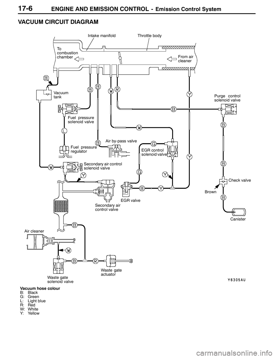
VACUUM CIRCUIT DIAGRAM
Vacuum hose colour
B: Black
G: Green
L: Light blue
R: Red
W: White
Y: YellowFrom air
cleaner
Intake manifoldThrottle body
To
combustion
chamber
Fuel pressure
regulator
EGR control
solenoid valve
Canister
EGR valve
Brown
Check valve Vacuum
tank
Fuel pressure
solenoid valve
Air by-pass valve
Secondary air control
solenoid valve
Secondary air
control valvePurge control
solenoid valve
Air cleaner
Waste gate
solenoid valveWaste gate
actuator
Page 819 of 1449

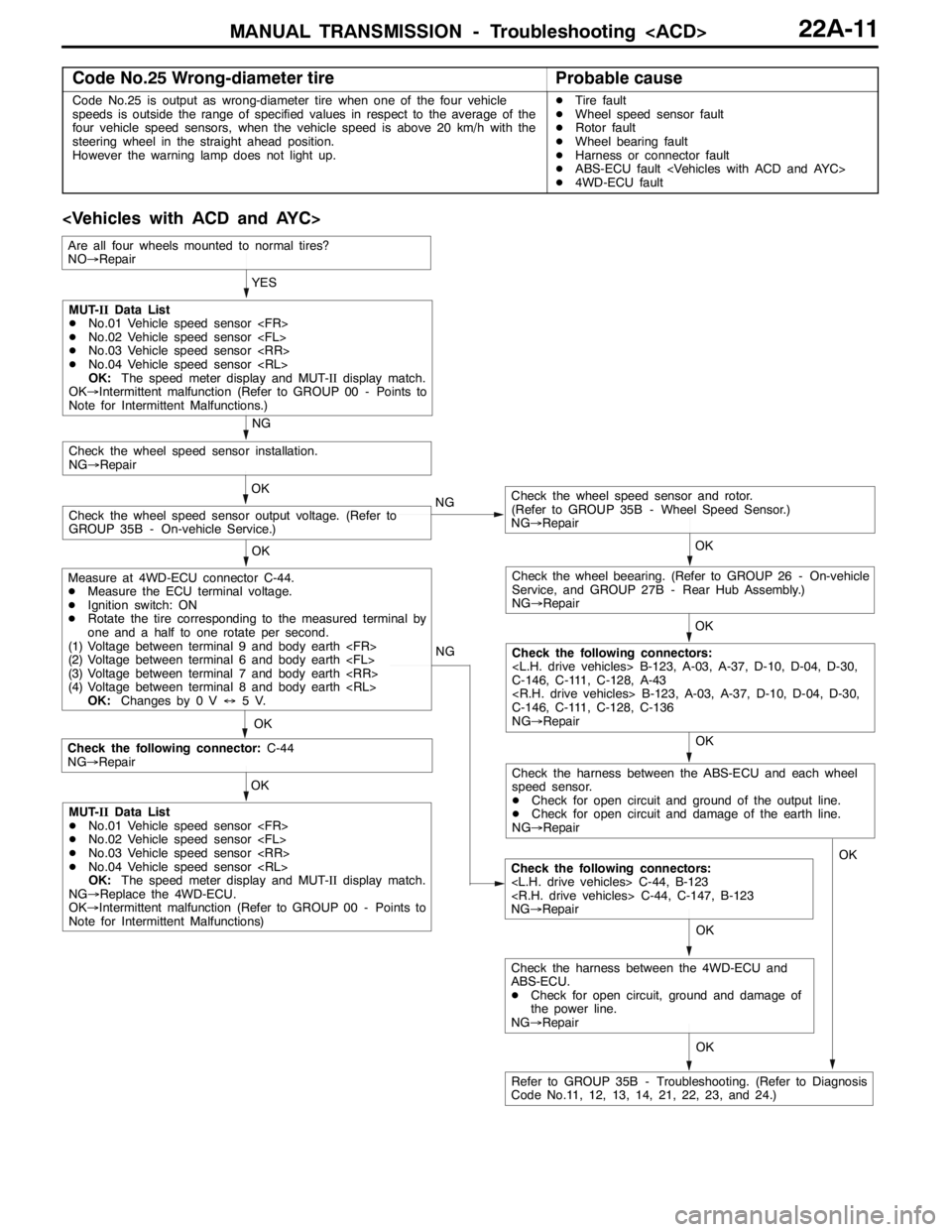
MANUAL TRANSMISSION - Troubleshooting
Code No.25 Wrong-diameter tireProbable cause
Code No.25 is output as wrong-diameter tire when one of the four vehicle
speeds is outside the range of specified values in respect to the average of the
four vehicle speed sensors, when the vehicle speed is above 20 km/h with the
steering wheel in the straight ahead position.
However the warning lamp does not light up.DTire fault
DWheel speed sensor fault
DRotor fault
DWheel bearing fault
DHarness or connector fault
DABS-ECU fault
D4WD-ECU fault
OK NG
OK
Check the following connector:C-44
NG→Repair
Check the following connectors:
NG→Repair OKYES
OK
OK
Check the wheel speed sensor and rotor.
(Refer to GROUP 35B - Wheel Speed Sensor.)
NG→Repair
Check the wheel speed sensor output voltage. (Refer to
GROUP 35B - On-vehicle Service.)OK
Check the wheel speed sensor installation.
NG→Repair
NG
OK
Check the wheel beearing. (Refer to GROUP 26 - On-vehicle
Service, and GROUP 27B - Rear Hub Assembly.)
NG→Repair
OK
Check the following connectors:
C-146, C-111, C-128, A-43
C-146, C-111, C-128, C-136
NG→Repair NG
MUT-IIData List
DNo.01 Vehicle speed sensor
DNo.02 Vehicle speed sensor
DNo.03 Vehicle speed sensor
DNo.04 Vehicle speed sensor
OK:The speed meter display and MUT-IIdisplay match.
OK→Intermittent malfunction (Refer to GROUP 00 - Points to
Note for Intermittent Malfunctions.)
Measure at 4WD-ECU connector C-44.
DMeasure the ECU terminal voltage.
DIgnition switch: ON
DRotate the tire corresponding to the measured terminal by
one and a half to one rotate per second.
(1) Voltage between terminal 9 and body earth
(2) Voltage between terminal 6 and body earth
(3) Voltage between terminal 7 and body earth
(4) Voltage between terminal 8 and body earth
OK:Changes by 0 V↔5V.
MUT-IIData List
DNo.01 Vehicle speed sensor
DNo.02 Vehicle speed sensor
DNo.03 Vehicle speed sensor
DNo.04 Vehicle speed sensor
OK:The speed meter display and MUT-IIdisplay match.
NG→Replace the 4WD-ECU.
OK→Intermittent malfunction (Refer to GROUP 00 - Points to
Note for Intermittent Malfunctions)
Refer to GROUP 35B - Troubleshooting. (Refer to Diagnosis
Code No.11, 12, 13, 14, 21, 22, 23, and 24.)
Are all four wheels mounted to normal tires?
NO→Repair
Check the harness between the ABS-ECU and each wheel
speed sensor.
DCheck for open circuit and ground of the output line.
DCheck for open circuit and damage of the earth line.
NG→Repair
OK
Check the harness between the 4WD-ECU and
ABS-ECU.
DCheck for open circuit, ground and damage of
the power line.
NG→RepairOK
Page 821 of 1449

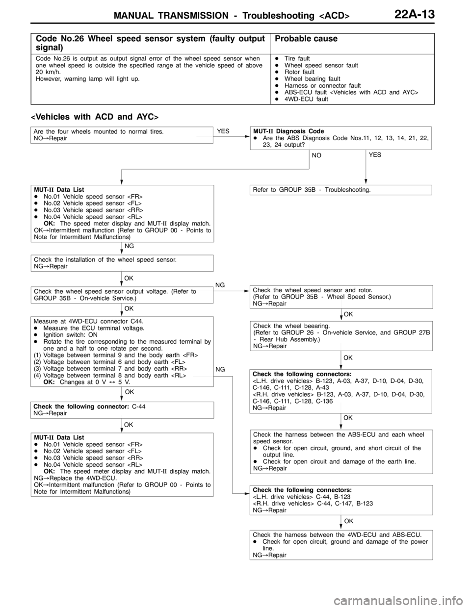
MANUAL TRANSMISSION - Troubleshooting
Code No.26 Wheel speed sensor system (faulty output
signal)Probable cause
Code No.26 is output as output signal error of the wheel speed sensor when
one wheel speed is outside the specified range at the vehicle speed of above
20 km/h.
However, warning lamp will light up.DTire fault
DWheel speed sensor fault
DRotor fault
DWheel bearing fault
DHarness or connector fault
DABS-ECU fault
D4WD-ECU fault
OK NG
OK
Check the following connector:C-44
NG→Repair
Check the following connectors:
NG→Repair OK
Check the harness between the 4WD-ECU and ABS-ECU.
DCheck for open circuit, ground and damage of the power
line.
NG→RepairYES
OK OK
Check the wheel speed sensor and rotor.
(Refer to GROUP 35B - Wheel Speed Sensor.)
NG→RepairCheck the wheel speed sensor output voltage. (Refer to
GROUP 35B - On-vehicle Service.)OK
Check the installation of the wheel speed sensor.
NG→Repair
NG
OK
Check the wheel beearing.
(Refer to GROUP 26 - On-vehicle Service, and GROUP 27B
- Rear Hub Assembly.)
NG→Repair
OK
Check the following connectors:
C-146, C-111, C-128, A-43
C-146, C-111, C-128, C-136
NG→Repair NG
MUT-IIData List
DNo.01 Vehicle speed sensor
DNo.02 Vehicle speed sensor
DNo.03 Vehicle speed sensor
DNo.04 Vehicle speed sensor
OK:The speed meter display and MUT-IIdisplay match.
OK→Intermittent malfunction (Refer to GROUP 00 - Points to
Note for Intermittent Malfunctions)
Measure at 4WD-ECU connector C44.
DMeasure the ECU terminal voltage.
DIgnition switch: ON
DRotate the tire corresponding to the measured terminal by
one and a half to one rotate per second.
(1) Voltage between terminal 9 and the body earth
(2) Voltage between terminal 6 and body earth
(3) Voltage between terminal 7 and body earth
(4) Voltage between terminal 8 and body earth
OK:Changes at 0 V↔5V.
MUT-IIData List
DNo.01 Vehicle speed sensor
DNo.02 Vehicle speed sensor
DNo.03 Vehicle speed sensor
DNo.04 Vehicle speed sensor
OK:The speed meter display and MUT-IIdisplay match.
NG→Replace the 4WD-ECU.
OK→Intermittent malfunction (Refer to GROUP 00 - Points to
Note for Intermittent Malfunctions)Check the harness between the ABS-ECU and each wheel
speed sensor.
DCheck for open circuit, ground, and short circuit of the
output line.
DCheck for open circuit and damage of the earth line.
NG→Repair YES
NO
Refer to GROUP 35B - Troubleshooting.
Are the four wheels mounted to normal tires.
NO→RepairMUT-IIDiagnosis Code
DAre the ABS Diagnosis Code Nos.11, 12, 13, 14, 21, 22,
23, 24 output?
Page 839 of 1449

MANUAL TRANSMISSION - Troubleshooting
INSPECTION CHART FOR TROUBLE SYMPTOMS
Trouble symptomInspection
procedure No.Reference
page
No communication possible between MUT-IIand all systems.122A-31
No communication possible between MUT-IIand 4WD-ECU.222A-32
ACD mode indicator lamp does not light up when the ignition switch is set to ”ON“
(engine is stopped).322A-33
More than two ACD mode indicator lamps remain lit even after the engine is started422A-34
The ACD does not operate (no diagnostic code).522A-34
The AYC does not operate (no diagnostic code).6Refer to
GROUPThe rear tire sounds when turning at low speed corners (vehicle slows down)7GROUP
27B.
Noise is produced from the torque transfer differential during turning.8
27B.
INSPECTION PROCEDURES FOR TROUBLE SYMPTOMS
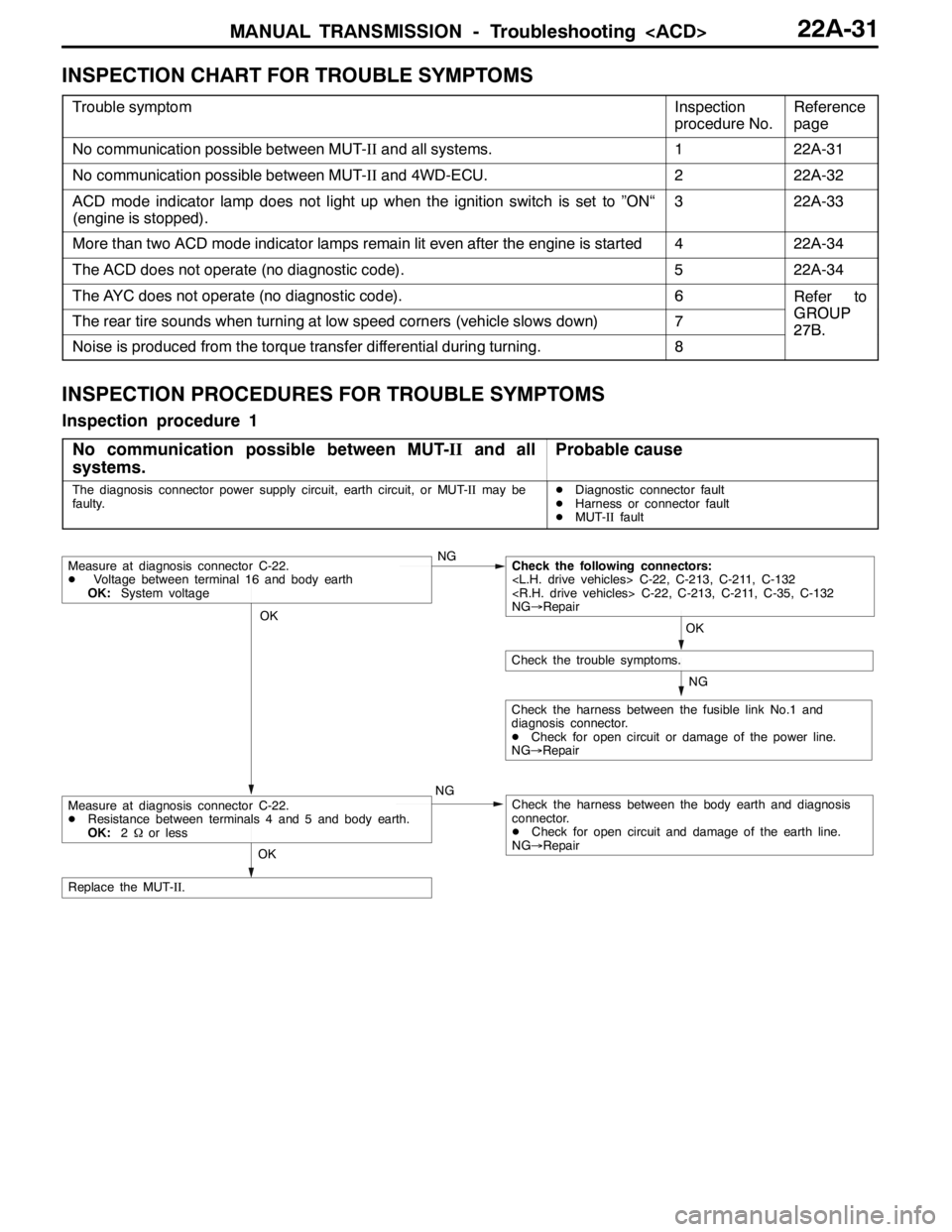
Inspection procedure 1
No communication possible between MUT-IIand all
systems.
Probable cause
The diagnosis connector power supply circuit, earth circuit, or MUT-IImay be
faulty.DDiagnostic connector fault
DHarness or connector fault
DMUT-IIfault
OK
NG
NG
Check the harness between the fusible link No.1 and
diagnosis connector.
DCheck for open circuit or damage of the power line.
NG→Repair
OK
Check the trouble symptoms.
Measure at diagnosis connector C-22.
DVoltage between terminal 16 and body earth
OK:System voltageNGCheck the following connectors:
NG→Repair
Check the harness between the body earth and diagnosis
connector.
DCheck for open circuit and damage of the earth line.
NG→Repair
OK
Replace the MUT-II.
Measure at diagnosis connector C-22.
DResistance between terminals 4 and 5 and body earth.
OK:2Ωor less